All published articles of this journal are available on ScienceDirect.

Retrofit, Restoration and Preservation of Byzantine Monuments: Assessment of Natural Degradation and Evaluation of Intervention Options
Abstract
Monuments reflect the depth and grandeur of a great civilization developed in a certain region, during a specific period of history. They possess aesthetic, historical and functional values. Undoubtedly, they are seen as part of mankind’s cultural heritage. In particular, the ecclesiastical byzantine monuments in countries where the byzantine civilization flourished, between the 4th and the 15th centuries, such as in Greece and Cyprus, are of great importance, because they are considered as edifices that offer, through their aesthetic and archeological study, a mental upgrade and valuable knowledge of roman and byzantine building techniques. Thus, the need for periodic maintenance and restoration of such monuments is imperative. The objective of the present work is to give a general description of the basic steps of the dominant retrofit methodology which is nowadays used in Greece and Cyprus and leads to the preservation of byzantine monuments. This method is the same as in any other type of monument and goes through four stages: (i) in-situ visual investigation of the degree of wear and on-site experiments, (ii) laboratory testing of the original materials of the monument under study, (iii) installation of a wireless sensor network on a monument under study, aiming at the most efficient monitoring of local displacements, differential foundation settlements, temperature changes, local humidity concentration, salt formation, etc. and (iv) evaluation of several retrofit options and the implementation of the optimal solution, by applying a formulated grading methodology. An immediate finding of the present work is that these steps enable the creation of a suitable analytical model which can be used in runnig a software package, for the design of a complete retrofit/restoration procedure and the preparation of accurate architectural and structural drawings, which will finally be used for the implementation of the maintenance/preservation design. Undeniably, what is important is to select the optimal retrofit procedure for this type of historical buildings, something which is explained in detail in this article. The latter statement expresses the scope of the present work. Another major finding of this review research is that the above retrofit procedure has already been applied to many byzantine monuments, during the past twenty years in Greece and in Cyprus and seems to have already become the dominant method over existing practices, because it uses modern technologies and is more efficient and effective, since it is based on optimization procedures.
1. INTRODUCTION
In applying retrofit and restoration procedures for the preservation of Byzantine monuments, in Greece and Cyprus, one of the most important targets is achieved in archaeology, which is to preserve these valuable treasures of international heritage. Nowadays, climatic changes and increased atmospheric pollution accelerate wear and damage to buildings. Undoubtedly, the Byzantine monuments are not exceptions at all. They need periodic maintenance and retrofit. In fact, this is the only way to prevent or limit natural corrosion phenomena.
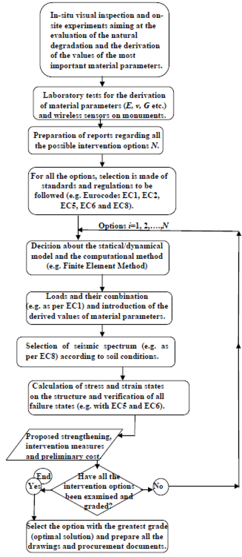
The careful determination of the corrosion factors (humidity, frost, etc.) and their mode of action on monuments, as well as the detailed layout, facade drawing and architectural detailing constitute the first stage of the design aiming to deal with problems caused by natural corrosion and degradation. This first step has to do with in-situ and laboratory testing of samples taken from the materials that constitute a monument, aiming at the evaluation of various material parameters. Next, by using national or international Standards and Specifications, the external forces acting on the monument and the design method to be applied are determined. Then, a model of the structure is set up and all necessary calculations are performed with the aid of computer programmes (commercial software packages), within the framework of the design or redesign of interventions [1]. The final step is the in-situ implementation of several practical methods (determined by design), such as the installation of reinforced concrete piles in the ground to strengthen the existing foundation, the use of special mortars for the sealing of cracks and the filling of gaps on stone masonries (caused by differential settlement of the foundation and seismic action), etc. Certainly, all the maintenance works must be a part of an optimal process of restoration of a monument (Fig. 1).
The basic criteria to be considered before a retrofit process is implemented on a historic monument [2], are the following: the increase of the compressive strength [3] of the load-bearing elements (stone masonry, columns, arcs, domes, etc.), the restoration of losses in the form and aesthetics, the protection of human life during the use of a monument and the continuous functionality and economy, both at the stage of maintenance and retrofit and at the stage of use of the monument. Thus, the methodology of such a retrofit process must be the best possible in each case, not only on the basis of techno-economic criteria but also on the basis of functional, aesthetic, archaeological and social criteria. Today, modern developments in technology help even more in the process of determining the optimal retrofit and maintenance procedures to be applied for these monuments, making them the dominant methods.
It is worth mentioning the application, for example, of wireless sensor networks in monuments. This modern domain of technology creates many prospects for further improvement of all the methods aiming at the accurate diagnosis of the degree and causes of wear, which by definition is the damage and gradual removal or deformation of material at the solid surfaces of a monument. Furthermore, the creation of modern and more advanced software (computer programmes) for the three-dimensional design of buildings, in combination with the new methods of topographic mapping, offers the possibility of faster, more efficient and more accurate vulnerability assessment and design or redesign of the restoration procedure [4]. In addition, modern software enables the manipulation of more complex but more accurate models of engineering analysis by applying approximation methods of high accuracies, such as, for example, the Finite Element method with grid refinement [5], which is a well-known method of computational Mechanics based on the fundamental principles of Engineering Mechanics [6]. The results obtained with this method are sometimes verified with those given by the “pushover analysis” (a type of non-linear static analysis based on an equivalent frame idealization of the structure), which has gained terrain in the last three decades and is considered as one of the most efficient numerical techniques, used to tackle problems in the domain of retrofit technology [7].
With the integration of the European Regulations, during the last four decades and the recent introduction of the mandatory implementation of the modernized and consolidated technical regulations, i.e., the Eurocodes, for the design of new structures or redesign of existing buildings within the European Union, expanded but at the same time safer and more economical design frameworks have been created, for retrofitting interventions on monuments. Since there is not yet an obligatory technical standard in the European Union for the seismic protection of monuments, general engineering principles about the protection of masonry structures and monuments against earthquakes and other types of loading can be obtained from certain Eurocodes, which can be used in combination with other standards aiming at the preservation and restoration of monuments. The recommended Eurocodes, which we believe are appropriate for this purpose and contain engineering principles, used in Greece and Cyprus, are the following:
- EC1 (design principles and determination of combinations of forces acting on the structures)
- EC5 (wooden constructions)
- EC6 (constructions made of load-bearing masonry)
- EC8 (seismic design of structures).
In parallel with these Regulations, in Greece, special local Regulations are used, compatible with the engineering principles contained in Eurocodes. Such a technical code is the Regulation for Evaluation and Structural Interventions in Masonry (R.E.S.I.M.), which is a detailed technical standard for interventions mainly in historical buildings with natural degradation (Fig. 2).
Next, in the rest of this article, some basic methods will be presented regarding in-situ and laboratory testing of material parameters. The method of wireless networks for monitoring changes in monuments, will also be discussed and the method of evaluation of options and decision criteria, for the restoration of the Byzantine monuments will be analyzed. Also, an example will be given together with a brief description of modern methods for the design of monument retrofitting. In the last section of this article, there will be conclusions and a few words about future work.
2. ASSESSMENT OF THE NATURAL DEGRADATION OF MONUMENTS
The main goal of retrofit, maintenance and restoration process and of structural health monitoring of monuments [8], is the understanding of the mechanical behavior of monuments [9-12] and the successful treatment of the natural “forces” of wear acting on them, so that sufficient resistance is achieved leading, in turn, to adequate durability. It is therefore important to determine, at first stage, as accurately as possible the type and values of these “forces”. Certainly, this is not an easy task.
Such “forces” of decay are gravity, wind, earthquake, humidity, frost, physicochemical reactions, biochemical reactions, landslides, fires, etc. Each of these actions causes a different type of damage on a monument; however, the result of the action of each one of these “forces” is combined with the results of the rest of the actions, with the detrimental consequence of the acceleration of the wear. Therefore, for example, frost causes the icy water, that fills the external cracks, to swell during the winter months. This phenomenon allows physical weathering to widen the cracks, which then facilitate the entry of other corrosive chemical agents, such as sulfur dioxide SO2 and nitrogen dioxide NO2, which are present in great quantities in the polluted atmospheric air and enter into the structure’s mass, through the enlarged cracks. The chemical reaction, responsible for the erosion of limestone, is presented below:
 |
(1) |
When acidic rainwater falls on limestone or chalk, the above chemical reaction takes place. New, soluble substances are formed in this chemical reaction. These dissolve in the water. The volume of CaSO4.2H2O salts generated, is greater than that of calcium carbonate CaCO3 and as a result, strong pressures are developed inside the cracks. These pressures are sometimes so high that they erode the stones of the walls. The above chemical reaction takes place both on the wall surface and inside the cracks and is facilitated by the presence of moisture. Often, the salts produced (on the right-hand side of the chemical reaction) appear on the wall surface in the form of a white powder that is washed away by the rain and thus leaving severe signs of corrosion. Nowadays, this chemical reaction is common in stone and marble monuments because the atmospheric air (mainly in big cities) is polluted by the emissions of harmful gazes coming from industries and vehicles. Atmospheric air is charged mainly with oxides of sulfur (S) and nitrogen (N), in much larger quantities than in the past.
The presence of moisture in the monuments not only facilitates the action of corrosive agents but at the same time creates favorable conditions for the development of imperfect organisms and non-vascular plants, such as mosses and lichens, which burden structural elements of the monument with the products of the induced biochemical reactions. These physicochemical and biochemical actions are continuous and may cause a gradual decrease in the strength and durability of a monument and consequently make it more vulnerable to seismic actions (Fig. 2).
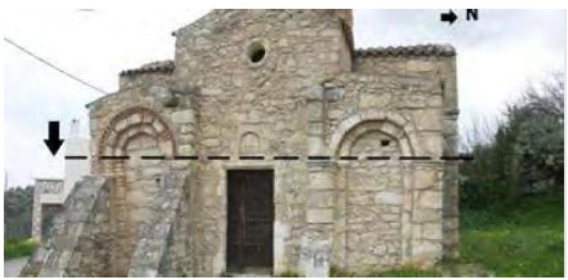
Taking into account all the harmful effects of certain corrosion factors and of external/internal forces (gravitational loads, live loads, wind loads, seismic actions, etc.) on an element of a monument, which through a suitable mathematical model are usually represented by a time function S(t), it is possible to stochastically monitor the phenomenon of the evolution of decay. Thus, considering that R(t) is the time function that expresses the strength (durability) of an element of a monument against the “forces” of wear and the external/internal forces, which have been mentioned above, we are interested so that at any time t the following inequality is valid [13]:
 |
(2) |
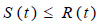
The above inequality indicates that with the appropriate remedial interventions to a monument, the result of the actions S(t) on an element of a structure is finally less than or at most equal to the strength R(t) of the element during the lifespan Tm of the monument (Fig. 3). If inequality (2) is reversed after the end of the time period Tm, which can last from a few years to a few decades or more, then retrofit must take place to increase the lifespan of a monument under study.
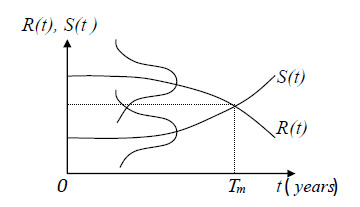
If we now assume that both the resistance and action values satisfy, as stochastic quantities, the normal Gaussian probabilistic distribution (Fig. 3), then what we require is that the value of the probability of exceedance Pf,t, regarding the resistance R(t), is less than or equal to the desired value Ptar,
 |
(3) |
where in the above inequality, the desired probability Ptar is, usually, equal to 0.1, for most historical monuments, with an index of importance (denoted with β) equal to the value of 1.3, in an environment in which the concentration of corrosive agents in soil and in the air is considered moderate. However, it should be noted that the probability value of 0.1 is considered, from a mathematical point of view, to be quite large. Obviously, this indicates how much important are the natural factors that cause damage to the monuments.
For the recording of deformations and calculation of the strength in each load-bearing element of a monument, the in-situ tests, as well as the laboratory tests, are necessary ([14, 15]). The most common methods are the following:
- Visual on-site inspection and use of the special camera for digital recording of displacements, etc.
- Use of diagnostic radar (Ground Penetration Radar).
- Penetration force measurement method (needle penetration test).
- Torque method (for the investigation of the degree of corrosion).
- Laboratory tests of resistance and of moisture content in wood.
Wireless sensor network to monitor the growth of moisture and salts and development of displacements.
Each one of these methods will then be presented in more detail in the sub-sections which follow.
2.1. Visual Examination of Natural Damage on Monuments
It is not uncommon to have interesting results by mere observation of a monument aiming to highlight the signs of time and wear, which give information about the degree of fatigue and the need to support and restore the monument. So, for example, looking at the cracks, the mosses and the lichens in stone masonry, we understand that the action of moisture and frost is strong enough and that maintenance is required. Therefore, in such a case, cracks need to be cleaned in depth. Deep grouting with a cement mortar that has elastic behavior must be applied. This work should be followed by an appropriate sealing of existing cracks, having a width not exceeding 10 mm and by inserting in the gaps a special type of cement with elastic properties and significant flexural strength in dry conditions. Note that Eurocodes allow much smaller crack widths and as already mentioned, their application is not compulsory but recommended in the case of monuments.
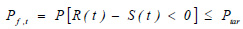
Moreover, by observing the collapsed parts of the walls and of the domes of a byzantine church (damage which was occurred at some time in the past due to seismic activity), we understand that it is necessary to re-install the stones which have fallen off or replace those that have serious damages with new stones (Fig. 4). In any case, the installation of stones on the masonry is made using scaffolding. Also, bonding materials, i.e., special mortars, offer high cohesion. Moreover, the installation of tendons as well as the application of reinforcing meshes (metal or polyethylene/polypropylene laths), covered by new mortar coatings (in place of those who have collapsed), are some usual methods used to increase the strength of a monument against earthquake actions [16].
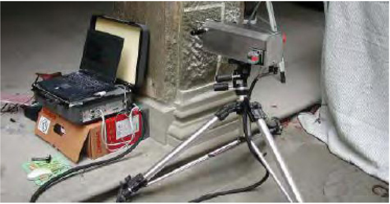
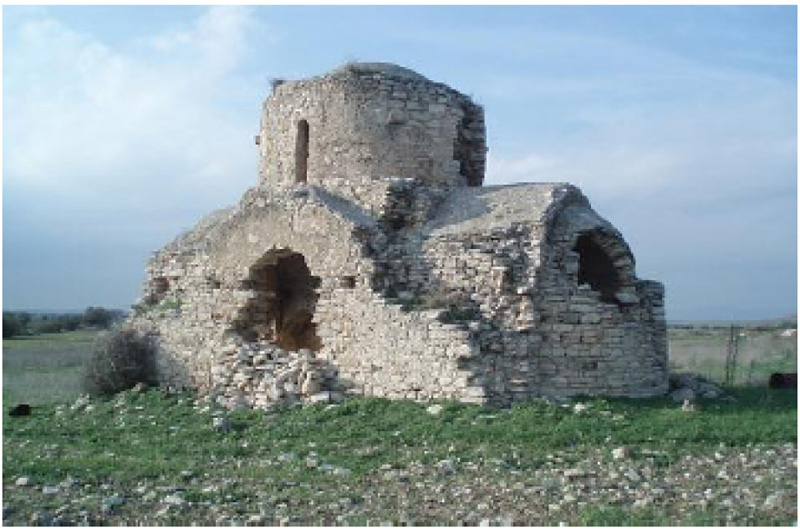
2.2. Use of Ground Penetration Radar
This method is used to detect and locate gaps or internal cracks in an element (load-bearing masonry, dome, pillar, etc.) of a monument and is an extension of the previous method (visual inspection). With this method, the Ground Penetration Radar (GPR) device is used, which, as indicated by its name, was first used to investigate gaps in the ground, since it generates transverse waves (similar in shape and frequency to seismic waves). These waves are reflected differently on each one of the surfaces of the inner gaps or discontinuities in the interior of the structural elements. From the analysis of the reflected waves, useful conclusions are drawn about the dimensions and depth of internal gaps or discontinuities.
In order for the investigation with a GPR device to be successful, it is necessary to make a proper test adjustment of the device beforehand to ensure that any errors due to the effects of the direct current with which the device operates or other negative effects from various external loads or displacements on the monument, are eliminated. Limitations in the use of this method are the presence of excessive moisture inside the structural elements, which causes refraction of the waves, as well as the existence of gaps or discontinuities very close to the outer surface that can cause overlap between the waves emitted by the device and the reflected waves.
2.3. Penetration Force Measurement Method
The penetration force measurement method (Fig. 5), also known as the needle penetration test, is used to check the degree of wear on the material of the load-bearing elements. This method measures the depth d at which a metal pin of standard dimensions of a special device can penetrate the material of an element.
The depth of penetration d is proportional to the force F exerted on the pin, which is measurable by means of a computer and can be pre-selected to have a constant value at each stage of the test. Thus, the linear relationship between these two parameters is as follows:
 |
(4) |
where the value of constant k results as the slope of the graph of F with respect to d (in a test on a material where F is allowed to vary). This constant is typical for each material and depends on the values of hardness and strength that the existing material exhibits and is expressed in units of force per unit length (kN/m). For a given value of F, as the value of k increases, from material to material or from position to position, the value of the penetration depth d becomes smaller and smaller. This means a healthy material with little physical wear. Conversely, for a constant value of F, as the value of k decreases, the value of d increases, which means that the physical wear inside the tested materials is progressing and that their resistance, hardness and strength are reduced.
The above test has another version which is called the “penetration test for historical masonry mortar,” and is well presented in [17]. It is based on the principle of “static” penetration. According to this version, a pin is driven at a constant velocity by a stepper motor which is controlled by a computer. The test result is the penetration load as a function of the penetration depth. The penetrometer is used on masonry walls with signs of decayed mortar. The objective of the test is to provide information about the mechanical characteristics of mortar (friction coefficient, cohesion, etc.).
2.4. Torque Measurement Method
This method of measuring the torque T, known as torque measurement method or torque penetrometric test, is analogous to the previous method. Torque is applied with a special device (Fig. 6) to investigate the degree of disintegration in the material of an element of an existing structure. With this method, the angle of rotation ω of a standard metal rod inserted in the material's mass is measured. The value of angle ω, which is recorded at the failure of the material, is proportional to the torque T applied, which is also measured with the aid of a computer connected to the device. It is expressed in units of force multiplied by unit length (N.m). The linear relationship between the two parameters is as follows:
 |
(5) |
where the value of the constant J results from the slope of the graph of T with respect to ω which is plotted after taking a series of in-situ measurements of these two parameters. Obviously, for a constant value of T and for fairly high values of J the values of ω are relatively small and thus the values of hardness and in-situ strength of the material, in a particular structural element, are considered to be high enough and therefore the retrofit measures to be taken are less strict than in cases where the value of J is much lower than the minimum allowable value of J, for the material under investigation.
Some other versions, with different fundamental characteristics of this type of in-situ test, are presented by other researchers. For example, in [18] a torque penetrometric test is proposed which is based on fracture Mechanics theory and is equivalent to the vane test used for soils. In this version of the torque measurement method the instrumentation is composed of a steel nail with four protruding teeth and a torque wrench. The test consists of several simple steps. The person who performs this test must be very careful while inserting the toothed nail into a mortar joint of a stone masonry wall or into any other material of an existing traditional building. Any damage to the material at this step will affect the result. Then, the next step is to apply a torque by means of a dynamometric key, until failure occurs. In [18] some interesting experimental results are given which were obtained in applying the method on the mortar of existing stone masonry. These results are presented in Table 1 (with CV equal to 15% for all results).
| Test | T [N.m] | Tv [N.mm/mm] | Test | T [N.m] | Tv [N.mm/mm] |
|---|---|---|---|---|---|
| TPT01 | 6.5 | 433 | TPT07 | 10.0 | 667 |
| TPT02 | 8.0 | 533 | TPT08 | 10.0 | 667 |
| TPT03 | 10.0 | 667 | TPT09 | 8.0 | 533 |
| TPT04 | 7.5 | 500 | TPT10 | 9.0 | 600 |
| TPT05 | 7.0 | 467 | TPT11 | 7.5 | 500 |
| TPT06 | 9.5 | 633 | TPT12 | 7.5 | 500 |
| - | - | - | mean value: | 8.4 | 558 |
Results in Table 1 indicate that the average value obtained by the in-situ experimental testing was T=8.4 N.m with a CV of 15%. In a study [18], the following empirical equation is proposed, which can be used for the derivation of the mortar strength σc:
σc={ Tv / [2(55De(De2 − Di2))0.5]}1.274 [MPa]
where the normalized ultimate torque Tv is defined as Tv = T/Lw (with Lw the depth of investigation at each test, set in the range between 15 mm and 20 mm). Normalized torque Tv is expressed in N.mm/mm and De and Di are expressed in mm and represent the diameters of the external and internal boundaries, respectively, of the domain occupied by the stress state investigated by the Torque Penetrometric Test (TPT). Their values are also given by the method. The results presented in Table 1 provide a mean value of Tv equal to 558 N.mm/mm, which is used in the above equation to calculate the compressive strength σc. After substituting the values of Tv, De and Di in the above formula, one obtains σc = 2.87 MPa. As per [18] there is only a 3% difference between the actual compressive strength obtained in the mechanical characterization and its estimated value with TPT. This low difference between the standard compression test results and the evaluation from the penetrometer readings suggests the reliability of the methodology proposed, returning low scattered results (CV=15%) and good precision in the prediction of the compressive strength of mortar, something which is very useful in the evaluation process.
2.5. Laboratory Tests of Resistance
The most critical tests of existing materials in a monument are the laboratory tests of compressive strength σc, of tensile strength σt and of flexural strength Μf. For this purpose, standard samples are taken from the load-bearing elements of a monument (columns, masonry, domes, etc.). These samples are then subjected to compression, bending or tension accordingly. In general, laboratory-tested specimens must be of standard dimensions, as per the specifications and the national or international standards, so that the results obtained are comparable.
The compressive strength σc is defined as follows:
 |
(6) |
where Fc is the compressive force imposed by the laboratory device and Aeff is the area of the active cross-section on which the compressive force is applied. The tensile strength σt is defined, accordingly, as follows:
 |
(7) |
where Ft is the tensile force acting on the active cross section Aeff of the laboratory specimen, imposed by a suitable device (Fig. 7). Some typical experimental results of compressive strength on samples taken from different positions of a sand-stone masonry of a monument in Cyprus (base, middle and top of the wall) are given in Table 2 (machine error= ±0.1kN):
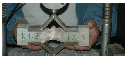
Also, some typical experimental results of tensile strength (Fig. 7) performed on samples taken from different positions of a historical mortar, on a monument, are given in Table 3 (machine error= ±0.1 kN):
Experimental results presented in Tables 2 and 3 are, of course, very useful in the evaluation process. The experimental values of compressive strength of sand-stone masonry and of tensile strength of historical mortar, can be used in the analysis performed with computer programmes, in which the values of such material parameters are introduced, for the computational model adopted for the analysis. Thus, when finite element analysis or any other numerical scheme is used, the values of compressive strength and tensile strength, taken from laboratory experiments, are introduced as real input data, together with the values of other parameters, for the analysis. Therefore, the numerical results of such analysis are more precise and more reliable and preservation measures to be decided are more effective.
| Specimen Nr (specimens 1 to 2 are taken from the top, 3 to 5 from the middle and 6 to 8 from the bottom of the wall) |
Force Fc applied [kN] |
Area Aeff of active cross section [m2] |
Compressive strength σc [MPa] |
|---|---|---|---|
| S01CS | 157.5 | 6.4X10⁻³ | 24.61 |
| S02CS | 154.2 | 6.1X10⁻³ | 25.28 |
| S03CS | 159.7 | 6.3X10⁻³ | 25.35 |
| S04CS | 163.4 | 6.8X10⁻³ | 24.03 |
| S05CS | 155.2 | 6.2X10⁻³ | 25.03 |
| S06CS | 158.1 | 6.5X10⁻³ | 24.32 |
| S07CS | 161.4 | 6.3X10⁻³ | 25.62 |
| S08CS | 156.2 | 6.1X10⁻³ | 25.61 |
| mean value: | 24.98 ± 0.599 |
| Specimen Nr | Force Ft applied [kN] |
Area Aeff of active cross section [m2] |
Tensile strength σt [MPa] |
|---|---|---|---|
| S01TS | 0.14 | 0.92X10⁻³ | 0.15 |
| S02TS | 0.12 | 0.88X10⁻³ | 0.14 |
| S03TS | 0.09 | 0.94X10⁻³ | 0.10 |
| S04TS | 0.08 | 0.89X10⁻³ | 0.09 |
| S05TS | 0.11 | 0.93X10⁻³ | 0.12 |
| mean value: | 0.12 ± 0.025 |
In the laboratory, it is possible to perform a test and obtain values of the flexural strength Μf, which must satisfy the following relation:
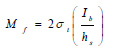 |
(8) |
where σt is the tensile strength defined by relation (7) above, Ib is the moment of inertia of the specimen about the bending axis and hs is the height of the specimen cross section. Both Ib and hs can be easily calculated by simply measuring the dimensions of the specimen’s rectangular cross section. Once the experimental value of σt is found, as explained above, the value of the flexural strength Μf is then obtained by applying equation (8). Thus, relation (8) is used to verify the result obtained in a test of flexural strength Μf. Also, knowing the value of σt and recording the corresponding laboratory value of deformation (strain) εt at failure, it is possible to calculate the modulus of elasticity E (Young’s modulus) by using the relation:
 |
(9) |
It is noteworthy that the values of tensile strength and flexural strength are extremely low in natural stone specimens compared to the corresponding values obtained for specimens made of steel.
Furthermore, from a laboratory test, one can measure the value of torque resistance Μz of a cylindrical sample of radius R and length L. In fact, in such a test, it is possible to measure the values of Μz and of the maximum angle of rotation θmax. With these two values, one can calculate the value of the shear modulus G from the relation:
 |
(10) |
where Jc is the moment of inertia of the cross section of the specimen, which is calculated from the relation Jc=(πR4)/2. The above relations appear in many books of Engineering Mechanics. It must be noted that the above tests are not applicable to wood. It is well known that wood is not an isotropic material and that it can easily gain or lose moisture from the air based upon the conditions of the surrounding environment. This variation of moisture content in wood causes changes in its properties [19].
With the known values of the shear modulus G and of the modulus of elasticity E, it is now possible to calculate the Poisson ratio of material, denoted by ν, from the known relation:
 |
(11) |
The values of parameters E, ν and G of the material under consideration are particularly useful in the design of the reinforcements (crack stitching, deep grouting, application of tension systems, etc.) by using an appropriate Finite Element method software that considers regional seismic activity, the classical theory of Engineering Mechanics and the fundamental principles of evaluation of restoration options [20, 21].
Reference [22] goes further to discuss performance-based seismic design and restricted interventions applied to unreinforced adobe masonry buildings. Through the experimental investigation conducted in laboratories, useful conclusions concerning the initiation and propagation of cracking failure are deduced. Experimental results verify that the response of adobe structures to horizontal loads is critically affected by weak bonding between the masonry units and mortar joints. However, experimental results must be interpreted within the general retrofit philosophy [23, 24] and by considering the general engineering principles [25, 26].
2.6. Moisture in Wood
The presence of moisture in wooden elements inside stone masonry (wooden reinforcement) and in wooden members on the roofs of byzantine churches of the 15th and 16th century in Cyprus, but also in their wooden door lintels and window frames, is one of the important factors that affect the strength and duration of such monuments.
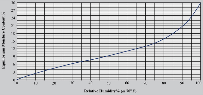
As a piece of wood dries, it first loses its free water and dips below the fiber saturation point (FSP). The FSP corresponds to roughly 30% moisture content (MC) in most wood species. The FSP may be roughly ±3% of MC depending on the wood species, but 30% of MC is the commonly-accepted average value for FSP. This means that regardless of the initial value of MC the wood begins to lose bound water and dimensionally shrinks when the weight of the remaining water is at a ratio of approximately 30% to the theoretical weight of the dry wood. It should be noted that in real-world situations, the FSP is never uniformly reached throughout the thickness of a piece of wood. A moisture gradient develops when the surface (i.e, the outer shell) is drier, with the interior (core) still being wet.
As the MC of wood drops below the FSP, it continues to lose moisture until it eventually stabilizes at a value that is commensurate with the surrounding moisture in the air. This is known as the point of equilibrium moisture content (EMC). The changes in the values of EMC depend on the fluctuation of the values of temperature and relative humidity of the surrounding air. In addition to the fundamental fact that wood is hygroscopic, perhaps the most crucial concept to understand, regarding wood and moisture, is the link between relative humidity and equilibrium moisture content. Fig. (8) presents the relationship between EMC and relative humidity RH. It gives valuable information about the behavior of wood regarding RH. In fact, humidity changes that occur within the range of 20% and 55%, have a small effect on EMC and hence result in smaller amounts of shrinking and swelling. However, when the value of RH in the wooden element of an existing structure, is greater than 18%, then in combination with certain values of temperature, favorable conditions are created for the insects, fungi and bacteria to attack the wood. Also, since moisture can cause swelling of the wood with unpleasant effects on the monument (appearance of cracks, deformation, functional problems, etc.) it must be detected during any retrofitting procedure. As it is well known, wood swelling can occur tangentially to the fibers, transversely (radially) to the fibers or along its fibers or in all three ways together (by volume swelling). The four forms of swelling are equally important because at high humidity levels, of the order of 80% to 90%, the increase in wood volume can take quite large values, as it is indicated in Fig. (8). Thus, a laboratory test aiming to find the moisture content in a wood sample is necessary. Such a test is quite simple.
A sample with standard dimensions is weighed before being placed in a special drying oven. If the indication of the scale before drying is wo and the indication after removal of moisture from the sample is ws, the percentage of moisture content cw,h is given by
 |
(12) |
while the volume moisture content is defined as
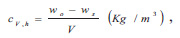 |
(13) |
with V being the volume of the sample.
2.7. Categories of Historical Mortars
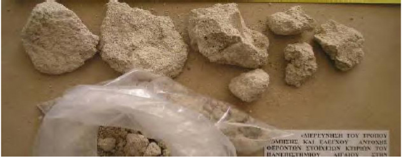
Existing coatings, binder lime mortars and in general, all types of mortar in byzantine monuments, consist of materials (e.g. calcium compounds, natural sand, etc.) whose composition was, in ancient times, the secret for the successful construction of buildings. Such a secret was known only by the architects and the builders of each project. Nowadays, it is possible to chemically and granulometrically analyze historical mortars in laboratories on samples taken directly from a monument (Fig. 9). Knowledge of such analysis is very important since it enables the reproduction of these mortars with the same composition, in order to recover the original overall strength of a monument which has been proven to withstand, for centuries, many seismic vibrations, daily wind pressures, live loads (imposed by the users), etc.
Certainly, modern technology offers more methods of classification of historical mortars. One of them is the Polarization-Fluorescence-Microscopy (PFM) technique which is much important nowadays for the characterization of ancient mortars because of the complex nature of these composite materials. It is well known that historical mortars are difficult to analyze due to the large variation in aggregate and pozzolanic contents. Mortars are also considered dynamic materials because they continue to interact with their environment after hardening and carbonation processes are complete. Thus, PFM is indispensable and is used as the first step in the characterization of this type of mortars, especially for the identification of the different inorganic and organic aggregates (inert) and of the different mineral additions (latent hydraulic) and also the identification of the binder type and of the binder-related particles and the description of the porosity of the material. The most commonly used fluorochrome is fluorescein isothiocyanate (FITC), with mean excitation and fluorescence emission wavelengths of about 490 nm and 525 nm, respectively. It has a barrier filter of 515 nm giving satisfactory results.
Early mortar formulations were primarily lime putty (slaked lime) and sand mixed in a ratio of 1 part lime putty and 3 parts sand by volume. Other ingredients could include crushed marine shells and brick dust. Animal hair and other organic material were also added. This basic formulation for mortar remained mostly unchanged for centuries until the creation of Portland cement. The vast majority of binders in historic buildings and monuments are made from lime. The process of preparation and use of lime mortars, was known to the Romans and was used by the masons during the byzantine era. The Romans and the technicians in many byzantine areas improved the technology of lime production and the use of lime mortar. Slaked lime mixed with volcanic ash found near Pozzouli at Naples Bay, gave a type of cement that hardens both in air and under water. The process of lime production was developed in Europe in the 18th century and took the form used nowadays. The modern process states that lime is produced by calcining or “burning” limestone and that lime mortars are made by mixing lime with sand or some other form of aggregate.
When considering mortars in historic buildings and monuments, it is useful to have an understanding of the history of their compositional development and use. On any approach to a monument of known age, an early expectation of the nature of the mortars can be formulated and tested once the mortars are examined. Conversely, if the building or monument is not well understood, the type of mortar may help to constrain its age. In general, however, natural hydraulic binders in combination with modern cements were not common in structures before the 18th century, when these began to be deliberately manufactured. Most modern mortars consist of a lime-based on the binder, of a varying degree of hydraulicity related to local limestone characteristics. Gypsum mortars and additions of gypsum to lime-based mortars are known in certain circumstances but are not generally very common.
2.8. Investigation of Wear with Wireless Sensors
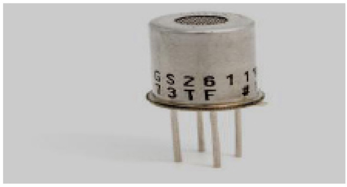
Wireless sensors [27] are a result of the advances in wireless communications, embedded computing, low-power VLSI circuits and especially in the technology of special electromechanical systems known as Micro-Electro Mechanical Systems (MEMS). This technological advancement has contributed to the development of multifunctional “smart” sensors of low cost and low power consumption, which are small in size and communicate with each other through human intervention, at short distances, as depicted in Fig. (10).
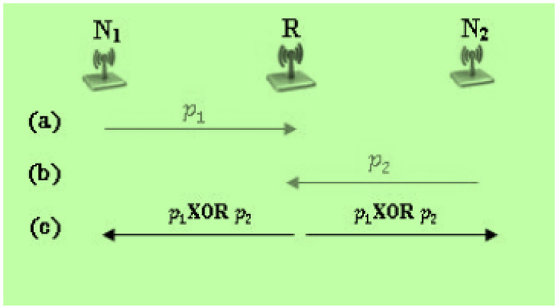
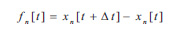
These tiny sensor nodes (Fig. 11), which consist of “smart” electronic circuits designed for wireless communication and data processing, have led researchers to the idea of a network of sensors based on the joint collaboration and operation of a large set of nodes (Fig. 12). The sensors send data in the form of time series to a central processing unit. These time series are of the form
 |
(14) |
and may be statistically processed. In relation (14), xn[t] is the position-time function for each sensor n. Such data may be the existence of salts or moisture in various parts of the monument, the concentration of biochemicals, etc., which indicate the type and size of the damage.
A network of wireless sensors in a monument consists of a large number of sensor nodes, which are densely developed in the building at various positions. The installation of the sensor nodes does not need to be pre-designed or decided in advance. However, depending on the type of technical investigations that are intended to be made (e.g. of temperature, humidity, salt formation, differential foundation settlement, local displacement, etc.), past experience guides the researcher to install a denser network of sensors in places where, for example, moisture and salt concentration appear (visually at least) to be more pronounced.
The basic design principles of a wireless sensor network are as follows:
- A sensor network must be resistant to errors that may occur due to a fault in a network subsystem or due to interference from an external cause. In this case, the operation error of a node or a group of nodes should not affect the overall operation of the network. It is worth noting that the reliability or error resistance function of a sensor node, denoted by Rn(t), follows the behavior of the Poisson distribution function and gives the probability of no failure in a period (0, t):
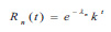 |
(15) |
where λn is the failure rate of a node n and t is the operation time. Constant k depends on the technical characteristics of the sensor node.
- The number of sensors installed in a monument to investigate the degree of wear can be of the order of one hundred or a thousand, depending on the area of the monument’s surface, the size and type of wear, but also the importance of the monument. The “installation density” μ(R) on a surface area A of the building (vertical or horizontal surface) is defined as follows:
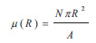 |
(16) |
where N is the number of sensors on the surface A and R is the average range of the wireless transmission. The quantity μ(R) can also be statistically treated.
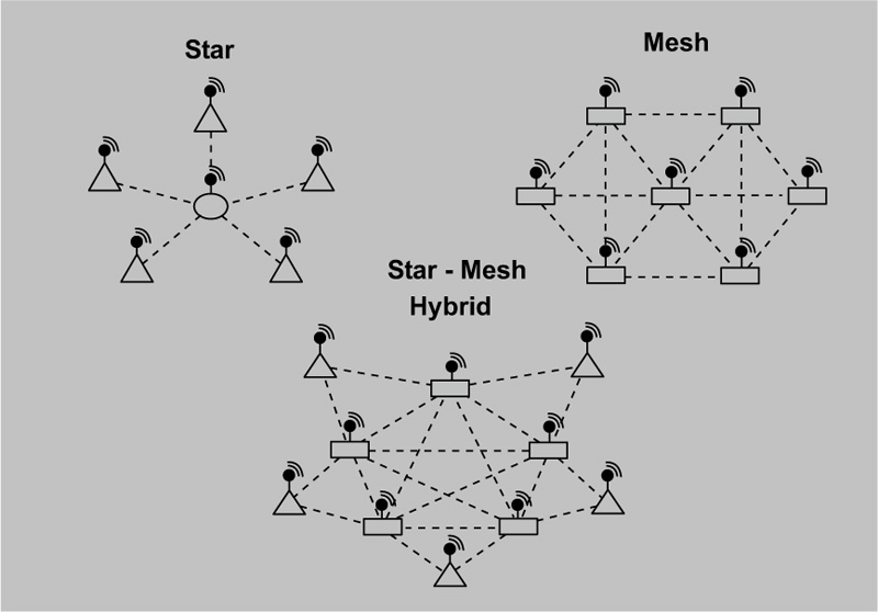
- The various communication possibilities, such as the directly connected WSN or the flat (ad-hoc and multi-hop) communication network system, give enough flexibility to the designer of a wireless sensor network system, to utilize the capabilities of the network by considering the available power distribution, in each category of sensors, in terms of signal transmission frequency (Fig. 13).
- The sensibility of a sensor depends on various factors. Exposure time and data processing capability are the most important factors of which the latter depends on the computing capacity of the sensor. Of course, all the factors depend on the manufacturing technology which is used for the production of sensors.
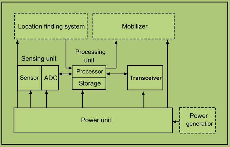
In general, a wireless sensor node consists of the following parts: a sensing unit, a processing unit, a transceiver unit and a power unit. The operation diagram of a wireless sensor is shown in Fig. (14).
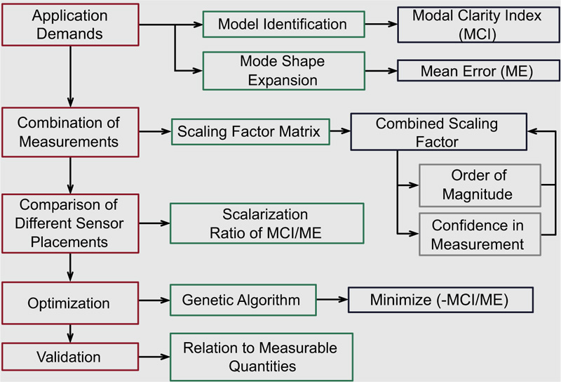
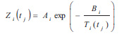
The whole strategy of installing the most suitable wireless sensors on the surface of a monument, with the main parameters developed above, is presented in the flow chart shown in Fig. (15). The better the network design, the better the management of the received data. Thus, for example, for the measurement of humidity it is necessary to adapt the network to the measurement of the electrical resistance Zi that presents, at different positions, the existing material of the monument, at different times tj and temperatures Ti(tj). The statistical treatment of the values Zi(tj) of electrical resistance and of Ti(tj), measured by wireless sensors, has resulted, in recent years, in the well-known Arrhenius time function:
 |
(17) |
where Ai and Bi are dimensionless constants that depend on the moisture content in the sample taken from the monument (usually values Ai = 100 Ω and Bi = 2000 K are taken for the design of wireless sensor networks). Thus, after appropriate statistical treatment of the values of Zi(tj), several values of moisture and salt concentration can be obtained at different positions and at different times tj. Then, after processing and careful study of this information and in combination with other observations, the most appropriate method of intervention for retrofitting and restoration is decided in each case.
After the completion of the in-situ visual inspection and the on-site tests on a monument and after performing laboratory tests, the architect/engineer or archeologist has all necessary technical information to proceed with further and deeper analysis and the design of intervention works, which will lead to a successful restoration and preservation of a monument under study. Values obtained of existing material properties (compressive strength, flexural strength, Young’s modulus E, Poisson ratio ν, etc.) and of local displacements and foundation differential settlements, are inserted in computer data files which are used by a suitable commercial package (computer program), within the analysis and design framework. Data files are necessary, for example, in cases where Finite Element Method analysis is used, for which material parameters, such as Young’s modulus E and Poisson ratio ν are employed in calculations and analysis. Therefore, several runnings of the programme are made, their number depending on particular structural difficulties and on how many intervention options are examined. As we will see in the following section, the process of selection of the optimal, in every respect, technical intervention solution highly depends on the expected additional strength and durability due to the proposed intervention measures. These factors are part of specific performances and monumental values, always to be examined in a typical evaluation of intervention options procedure, which will be discussed in the next section.
3. EVALUATION OF INTERVENTION OPTIONS
The main philosophical challenge presented to a group of experts (Architect, Civil Engineer and Archaeologist) is the choice between a retrofit intervention that ensures that monumental and aesthetic values are preserved and an intervention that guarantees the safety of the monument against collapse. Obviously, the second option is the one that will ultimately be taken into account (life protection) because the safety of the individuals who are using a monument prevails without, however, disregarding its monumental and aesthetic value.
The intervention parameters, which correspond to monumental values, are defined as follows:
- (M1) The preservation of the form and aesthetic value by choosing to have little damage.
- (M2) The preservation of the historical value by choosing partial or total removal of later additions.
- (M3) The preservation of the technical value by choosing a significant or a little replacement of the original materials of the monument.
In order to take a decision on the type of intervention to be applied for retrofitting a monument, a priority must be set regarding the necessary safety conditions to be established during its use. Thus, an appropriate technical procedure is selected and developed in terms of its impact on all the five performances of the structural retrofit solution decided. These five performances are the following:
- (E1) The possibility of reversing part of the intervention measures taken.
- (E2) The possibility of repeating the implemented measures within fifty years.
- (E3) The additional strength is provided by the measures and the reinforcing elements.
- (E4) The reliability of the proposed intervention regarding the given economic conditions.
- (E5) The benefits for the users, related to different domains (e.g. tourism, cultural events, etc).
It should be noted that the cost (K) must be added to the three “monumental” values Mi and the five performances Ei.
The above philosophical approach to the issue of retrofit and restoration is developed in more detail in the book of the academic T. P. Tassios [23]. As we have already mentioned the protection of human life is a priority for the decision-makers. Then, it follows that for the same level of safety and always regarding the protection of human life, it is possible to have two or more intervention solutions which may involve different levels or types of damages and physical wear to a monument. It is, of course, obvious that one would prefer the solution which, for a particular seismic force, would ensure the lowest possible level of damage. But a critical question arises: Is this solution less reversible or less durable or less feasible? How important would the measures of such a solution be in the case of a presumably higher level of damage corresponding to a stronger earthquake?
The above thoughts lead to the following conclusions:
- The final choice cannot ignore the three monumental values Mi, the five technical performances Ei and the cost K.
- The comparison between any two proposed intervention solutions cannot be done only with purely technical criteria. Definitely, beyond the aesthetic, historical and social criteria, some other criteria related to the ecclesiastical tradition intervene in the evaluation procedure.
In order to facilitate the selection of the optimal, in every respect, technical intervention solution, we need to resort to the method of scoring the solutions. However, before formulating the grading methodology, it is important to mention the importance of the actions that are considered at the stage of the restoration study of an ecclesiastical monument and of any monument. The main concern is focused on the assessment of accidental actions. In Cyprus and in Greece, the most common and important action, in the life time of a monument, is the seismic action SE, whose main characteristics (e.g., ground acceleration, dominant period, etc.) are taken into account by the designers at the very first stage of investigation of proposed alternative solutions. At this point, it should be emphasized that the value of the seismic action SE depends on the following key parameters:
(a) The history related to a monument and the need to preserve its original identity, necessarily lead to the selection of high values of seismic action SE, in order to avoid the collapse of the monument when such a strong earthquake comes. But this choice leads to greater alterations of the form due to the special interventions that it requires.
(b) The cost of retrofitting works on a monument is significantly lower than the cost of the erection of a new building of the same form and of the same dimensions, with modern materials. This means that the impact on the national economy, caused by any programme of maintenance of historical monuments, is negligible. Therefore, it is easier to accept, in any design, high values of seismic actions SE and therefore, more expensive intervention measures, which definitely lead to safer solutions.
(c) The frequency of use of byzantine monuments is significantly lower than in the case of houses or public buildings. However, this parameter does not affect the value of seismic actions SE selected for the design.
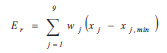
Based on the above parameters, the solution that receives the highest rate Er, among the proposed solutions, is defined as the optimal intervention structural solution. The score or rate of each proposal (solution) is also called efficiency index Er and is defined as follows:
 |
(18) |
where xj is the value (from 1 to 9) given to each of the nine retrofit parameters, i.e. the three “monumental” values (M1 to M3), the five performances (E1 to E5) and the cost (K). In relation (18) parameter xj,min is the minimum value that the designer could accept (usually it is xj,min = 1). Quantity wj is the weight factor of each characteristic j. Its value is decided by the designer and expresses its importance when compared with other characteristics. Obviously, then, it is
 |
(19) |
The above algorithm is applied for different values of the seismic action SE. Finally, an appropriate selection is made of the value of the seismic action, such that it maximizes the value of the efficiency index Er. Thus, in order to better understand the way in which the above methodology is applied, the following example is given. It must be emphasized that the retrofit procedure, already described in the present article, has been applied to many Byzantine monuments, during the past twenty years in Greece and in Cyprus and seems to have already become the dominant method over existing preservation practices. This is because it has fundamental merits: it uses modern technologies and is more efficient and effective since it is based on updated retrofitting methods and optimization procedures.
| S.No | Proposed Technical Solution | Remarks |
|---|---|---|
| 1 | Stitching of large cracks, with an opening larger than 5mm, which exist in the upper half of the walls, will be the first stage of works. Moreover, the wooden beam mantle at the upper half of the perimeter masonry walls must be strengthened. The current proposal also includes the strengthening of the foundation by supporting it on the rock layer, which is beneath the soft soil foundation layer. | In order to fully restore the original form of the monument and to unload the north wall, by removing all unnecessary loads, it has been decided to demolish and remove the existing wooden canopy on the north side of the chapel. |
| 2 | In this solution the same methodology of interventions is applied as in the previous proposal, with the difference that instead of strengthening the foundation and the existing wood beam mantle, it is decided to build three retaining stone walls, for each one of the two large stone masonries (north and south), against horizontal seismic loads in the north-south direction. | This solution includes maintenance and repair of the canopy and of its support on the north wall. |
| 3 | The third solution is similar to the first with the difference that instead of strengthening the foundation by supporting it on the rock layer, it is decided to double the thickness of the existing stone foundation with transverse slabs of reinforced concrete (at least 40 cm thick) fabricated transversely and at stages, beneath the entire perimeter foundation, in the form of “boxes”. | Demolition and removal of the canopy on the north side of the ecclesiastical monument have been planned. |
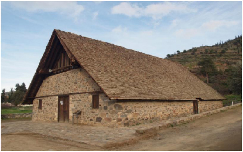
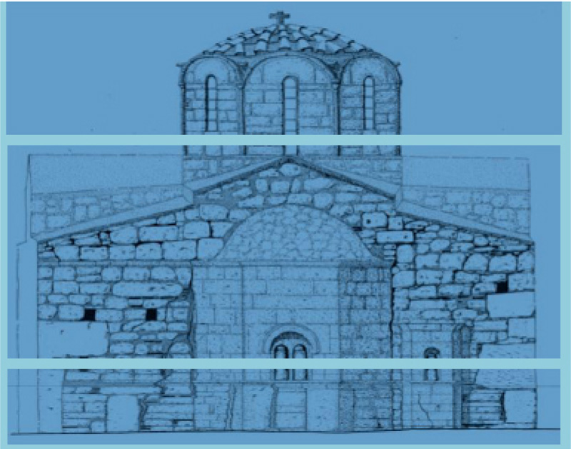
EXAMPLE: In a stone-built with wooden roof church of the 15th century, situated in the Troodos Mountains on the island of Cyprus, the following failures have been observed (Fig. 16):
- The wooden roof was displaced at some time in the past due to earthquakes. This displacement has caused local damage to the upper half of the stone masonry in the perimeter of the monument.
- Due to the uneven distribution of the soft soil under the foundation of the building, the differential settlement has taken place between the north and the south side of the building, of the order of 8 to 10 cm. Also, due to the earthquakes which took place in the past and the aforementioned soil peculiarities, the north and south walls of the church have been slightly diverted outwards.
- In a later period (in modern times) a wooden canopy was added, which rests on one side on the north wall of the temple and on the other on simple wooden colonnades. The aesthetic image of the north side of the monument is not good due to natural wear. In addition, it has been found that the additional loads on the north wall, due to the above-mentioned canopy installed sometime during the 20th century and being partially supported by the north wall, have much contributed to the existence of the aforementioned problems.
All proposals regarding the structural restoration of this ecclesiastical monument include an essential work; that is the filling of the cracks with a suitable bonding mortar of satisfactory strength, as well as minor local repairs on the stone masonry. Also, in all retrofitting solutions, it is recommended that the roof is reinforced so that it behaves as rigid construction, with adequate strength against seismic loads, in the horizontal sense. The following technical solutions are therefore proposed and considered to be the most usual in the case of stone monuments:
(I) Stitching of large cracks, with an opening larger than 5mm that exist in the upper half of the walls, will be the first stage of restoration works. Filling of the cracks with a suitable bonding mortar of satisfactory strength, as well as minor local repairs on the stone masonry, will follow. Moreover, the wooden beam mantle at the upper half of the perimeter masonry walls must be strengthened by installing double wood beams inside and outside, on the top of the two large stone walls (at the north and the south sides), near the roof supports, as indicated by the analysis. The two wooden beams must be connected with stainless or galvanized steel spiral rods. The current proposal (analysis) also includes the strengthening of the foundation through the excavation of pits with a diameter of 0.8 m and a depth of 1 to 2 m, until the rock layer is reached, which is beneath the soft soil foundation layer. The pits should be excavated below the perimeter foundation or adjacent to it, at intervals not exceeding 3 m, starting from the corners. They will then be filled with reinforced concrete of category C30/37. For security reasons, this work will be done in stages, i.e., one or two such foundation reinforcements will be completed before the construction of the next two starts, etc. In addition, in order to fully restore the original form of the monument and to unload the north wall, by removing all unnecessary loads, it has been decided to demolish and remove the existing wooden canopy on the north side of the chapel.
(II) In this solution the same methodology of interventions is applied as in the previous proposal, with the difference that instead of strengthening the foundation and the existing wooden beam mantle, it is decided to build three stone walls, for each one of the two large stone masonries (north and south), as per the results of Finite Element analysis. These additional walls will be constructed at the corners and at the middle and will form an angle of 90o with the existing masonry. They are intended to function as retaining supports against earthquake forces. In other words, they are designed to resist horizontal seismic loads in the north-south direction, in which the monument has some weaknesses. These supports are founded by reinforced concrete piles, embedded in the rock layer which is below the surface soft layer of soil. Also, this solution includes maintenance and repair of the canopy and of its support on the north wall.
(III) The third solution is similar to the first and a similar analysis is made, with the difference that instead of strengthening the foundation by supporting it on the rock layer, it is decided to double the thickness of the existing stone foundation with transverse slabs of reinforced concrete (at least 40 cm thick) fabricated transversely and at stages, beneath the entire perimeter foundation, in the form of “boxes”. Also, demolition and removal of the wooden canopy on the north side of the ecclesiastical monument, have been planned.
All the above proposals are presented in Table 4. In the case of this ecclesiastical monument, both its religious (spiritual) and historical values are quite high, resulting in the need to preserve the monument and avoid its collapse by an earthquake. The second solution considers a greater seismic action SE than the other two solutions. However, among the interventions proposed, the second option leads to aesthetic deterioration. In fact, the first and the third solutions focus on the preservation of the original form of the monument, while the second solution does not. In terms of cost, the second solution is the most expensive. Thus, the values of the weights of each one of the nine characteristics for each one of the above solutions are listed in (Table 5). The lower the value given to a characteristic, the lower is the importance attributed to it, in each one of the solutions sought. Also, for the specific example and considering the experience gained in the past, it is decided that for all the characteristics of the proposed solutions, it is xj,min=1. The values of the weights wj are determined by experience and remain constant for each characteristic in all three solutions, as shown in Table 5.
In applying the methodology presented above, it becomes clear that the first solution should be selected. Moreover, the first proposal has the highest efficiency index Er and therefore, it is the solution to be applied. If in the course of the implementation of this solution, practical or other issues arise that hinder its implementation, then the third solution is followed, with a score lower than that of the first but greater than that of the second.
CONCLUSION
In this work, the problem of retrofitting, maintenance and restoration of ecclesiastical Byzantine monuments has been studied. In this article, the assessment of natural degradation on this category of historic structures has been presented and the process of evaluation of intervention options has been analyzed. The whole process is presented in the flow chart in Fig. (17), which illustrates the idea and work of the present paper.
The fundamental conclusions derived from the above discussion, which concern a retrofit procedure on a monument, are the following:
(i) The first retrofit step is the careful evaluation of the natural “forces” that cause ware to the traditional or historical materials on the monuments. This very first step includes an assessment process based on in-situ standard inspections and tests. It includes a visual inspection of monuments aiming at the visual examination of the cracks and of the traces of moisture action, followed by standard tests performed on the site, such as the Ground Penetration Radar (GPR) test, the penetration force measurement method, which is also known as the needle penetration test and the torque measurement method or torque penetrometer test (TPT).
(ii) The second step in a retrofit procedure has to do with standard laboratory tests. Such tests are the laboratory tests of compressive strength, the tensile strength test, the torque resistance test, the equilibrium moisture content (EMC) test and the chemical and granulometric analysis of historical mortars in laboratories. All these laboratory tests are performed, as per technical standards, on samples taken directly from a monument under study.
(iii) At a third retrofit step, a wireless sensor network is installed on a monument, aiming at the most efficient monitoring of local displacements, differential foundation settlements, temperature changes, local humidity concentration, salt formation, etc. All data collected by such a network system is both empirically and statistically examined and analyzed. All conclusions derived from this analysis, in combination with in-situ and laboratory test results, lead to appropriate analytical structural and computational models.
(iv) The fourth retrofit step involves the evaluation of several retrofit options and the selection and implementation of the optimal solution. At this stage, the optimum option is selected by implementing certain architectural, historical, engineering, safety, aesthetic and economic criteria. All these criteria are combined with cost. They are divided into two categories: three monumental values and five performances. A formulated grading methodology is applied for each one of the proposed retrofit solutions, in which all criteria and costs are associated with a weight. The solution with the greatest grade prevails and is implemented in practice. It is used for deeper structural analysis and the final retrofit design.
The major finding of this review research is that the above general retrofit procedure has already been applied to many Byzantine monuments, during the past twenty years in Greece and in Cyprus and it seems that this method is already the dominant procedure over existing practices, because it is cheap, it uses modern technologies and is more efficient and effective since it is based on optimization procedures. Thus, it can be used in cases where a low budget is an obstacle, since it leads to an optimal solution, in which the economic criterion is among the essential factors of the method. In future work, we will emphasize the necessity of international Standards and Technical Specifications, in a retrofit procedure. Certainly, in future work, the above retrofit methodology will be expanded and will include the presentation of numerous structural repair techniques such as stitching of large cracks, filling of cracks with a suitable bonding mortar and strengthening of stone masonries with additional wooden mantles, etc. However, a detailed presentation of these techniques and of certain analytical treatments is left for future work.
LIST OF ABBREVIATIONS
| Retrofit of Monuments | = Process of installation of modified elements and/or appropriate materials on a monument, aiming at increasing its resistance against several types of loading (e.g., earthquake) and against the corrosive activity |
| Maintenance of Monuments | = Conservation and technical restoration procedures applied to monuments aiming at their preservation and the presentation of their aesthetic and historical value |
| Assessment of Natural Degradation of a Monument | = Technical process of judging or deciding the degree of action of corrosive factors (of chemical or mechanical type) on a monument |
| Wear and Corrosion of a Monument | = Damage and gradual removal or deformation of material at the solid surfaces of a monument |
| GPR | = Ground Penetration Radar |
| TPT | = Torque Penetrometric Test |
| EMC | = Equilibrium Moisture Content |
CONSENT FOR PUBLICATION
Not applicable.
FUNDING
None.
CONFLICT OF INTEREST
The author declares that there is no conflict of interest.
ACKNOWLEDGEMENTS
The author is grateful to the anonymous reviewers for their valuable comments.

