All published articles of this journal are available on ScienceDirect.

Ultimate Behaviour of Perforated Steel Plate Girders Subjected to Shear Loading
Abstract
Background:
The Perforated Steel Plate Girders (PSPGs) are those Steel Plate Girders (SPGs) that have openings in their web. The PSPGs are significant structural members to withstand bending mainly. The proper combination of steel plates is applied to fabricate the PSPGs. When the available rolled steel profiles cannot carry the applied loads, the use of beams made of the steel plates is unavoidable.
Objective:
The present paper presents the ultimate behaviour of PSPGs subjected to shear loading.
Methods:
In order to carry out the study, the finite element method is used as a practical design tool for predicting the ultimate behaviour of the PSPGs under shear loading. Two experimentally tested PSPGs are selected to conduct the modelling accuracy using ABAQUS. All the features of the tested specimens are considered in the modelling. The finite element modelling results are compared with the experimental tests results, which verify the modelling. Since the accuracy of the modelling is demonstrated, thereafter, the method is used for the nonlinear analysis of the developed PSPGs having different circular and rectangular openings. Various parameters are adopted in the analysis to vastly evaluate their effects on the ultimate behaviour of the PSPGs. The parameters include shape of the openings (circular and rectangular openings), number of the openings (2 and 4 openings), arrangement of the openings (horizontal and vertical openings), using steel frame around the openings, utilising diagonal steel stiffeners to connect the steel frame to the corners of the PSPGs, and thicknesses (2 mm and 4 mm) of the steel frame and the diagonal steel stiffeners.
Results:
The obtained results from the nonlinear analysis of the PSPGs are summarised considering various parameters. The results are compared and discussed, taking into account the effects of the parameters on the ultimate behaviour of the PSPGs.
Conclusion:
The study highlights that the shape of the openings affects the behaviour of the PSPGs. Accordingly, circular openings are preferred compared with the rectangular ones. Also, as the number of the openings is increased, the ultimate capacity of the PSPGs is reduced. The behaviour of the PSPGs is considerably affected by the arrangement of the openings in which the horizontal openings have better performance than the vertical ones. If the steel frame and/or the steel stiffeners are utilised, the ultimate capacity is enhanced. The ultimate capacity of the PSPGs is improved by increasing the thickness of the steel frame and/or stiffeners. The failure modes of the PSPGs with circular and rectangular openings are indicated and evaluated.
1. INTRODUCTION
The SPG is a flexural member fabricated by the use of riveting, bolting, or welding. In general, the SPGs comprise of two flange plates and one web plate attached together to form a cross-section with I shape. The SPGs are more cost-saving than the rolled steel beams, in addition to their appropriate performance against the applied loads. The web of the SPGs is employed thinner than their flanges, which decreases their weight and leads to the favourable result from the structural viewpoint. On the other hand, this thin web results in the buckling or yielding of the SPGs by the shear forces before obtaining their ultimate flexural capacity.
Since the SPGs have a large depth, they occupy a large space of the structures. The use of the openings in the web of the SPGs has been proposed by researchers to optimise the use of this space and mainly for the installation works. However, these openings have caused lower ultimate capacity and local buckling of the SPGs.
Modern SPGs are fabricated by welding transverse steel stiffeners, in addition to the two steel flanges and one steel web. The main function of using the bottom and top steel flange plates is to resist the bending moments. This resistance is obtained by the development of the axial tensile and compressive stresses from the bending action. The steel web resists the shear stresses. The thin steel web is subjected to a large shear force and thus, undergoes the shear buckling.
Some studies have been conducted on the SPGs and PSPGs to evaluate their performance. Höglund [1] tested a series of four girders of structural carbon steel with two, three, or four openings in their web without web stiffeners to investigate their strength. A method for calculating the collapse load of a plate girder loaded in shear and bending was presented by Evans et al. [2]. The ultimate strength of the plate girders with webs containing circular openings was assessed [3, 4]. The behaviour of plate girders with web openings and horizontally curved plate girders with circular openings was studied [5-7]. Experiments were carried out on six composite and two plain SPGs under shear loading by Shanmugam and Baskar [8] to indicate the elastic and inelastic behaviour of such girders. Numerical and experimental tests on stainless SPGs loaded in shear were performed by Estrada et al. [9, 10] to understand their response better. Hagen et al. [11] undertook numerical simulations to develop a design model for the shear capacity of steel girders with web openings, with and without transverse stiffeners. The design procedure for the shear capacity of steel girders with large web openings was modified by Hagen and Larsen [12] based on the numerical simulations. Shear strength of stiffened plate girders was numerically examined [13, 14]. The effect of initial geometric imperfections on the post-buckling behaviour of longitudinally stiffened plate girder webs was evaluated under the patch load by Graciano et al. [15]. Shear failure mechanism characteristics of full-size lean duplex stainless SPGs were analysed using the finite element modelling by Hassanein [16]. Hassanein and Kharoob [17] numerically studied the shear behaviour of transversely stiffened hollow tubular flange plate girders. Chacón et al. [18] reported the results of six experimentally tested SPGs subjected to the patch loading as well as the results of forty-eight numerically-tested girders to assess their ultimate load capacity. Aleksić et al. [19] presented experimental tests on twelve SPGs subjected to the patch loading and comparisons of the obtained ultimate loads with their proposed mathematical model. The structural behaviour of three SPGs was experimentally examined under shear by Hamoodi and Gabar [20]. Yingjiang et al. [21] conducted experimental and numerical investigations on plate girders with perforated web under the axial compression and bending moment to study their failure behaviour. The distribution of the plane stress and shear strain on the cross-section of plate girders subjected to the interaction of the bending moment and high shear force was evaluated by Zhu and Zhao [22] by conducting tests on eight plate girders with deep section and also nonlinear finite element analysis. Nonlinear finite element analysis of the shear behaviour of lean duplex stainless SPGs was reported by Armoosh et al. [23]. Liu and Guedes Soares [24, 25] experimentally and numerically assessed the crushing force of girders with stiffened web under local in-plane loads. El-Khoriby et al. [26] numerically investigated the effects of eccentric web openings on the strength and behaviour of hollow tubular flange plate girders. Chacón et al. [27] offered a mechanical formulation to estimate the strength of transversally stiffened SPGs with closely spaced stiffeners under the patch loading. Strength of steel girders with corrugated web plates and high-strength steels was numerically studied by Hassanein et al. [28]. The buckling strength and post-buckling capacity of high-strength SPGs were examined utilising the nonlinear finite element analysis by Xiao et al. [29]. Chen et al. [30] experimentally and numerically examined the shear buckling behaviour of welded stainless SPGs with transverse stiffeners. Truong [31] numerically analysed the effect of multiple longitudinal web stiffeners placed at their optimum location on the ultimate strength of SPGs under the predominant shear loading, and combined bending and shear loading. Numerical analysis of high-strength and mild SPGs without longitudinal stiffeners was carried out by Xiao et al. [32] considering the post-buckling capacity. Shawky and Nabil [33] performed experimental and numerical investigations on the ultimate strength and post-buckling behaviour of plate girders under shear and bending stresses.
As can be witnessed from the above mentioned literature, the available studies on the ultimate capacity of the PSPGs subjected to shear loading using the considered parameters of this study are rare, which is performed herein.
This paper is concerned with the ultimate capacity of the PSPGs under shear loading. After 3D modelling verification is established using ABAQUS, the PSPGs are developed adopting different parameters. The parameters consist of shape of the openings (circular and rectangular openings), number of the openings (2 and 4 openings), arrangement of the openings (horizontal and vertical openings), using steel frame around the openings, utilising diagonal steel stiffeners and thicknesses (2 mm and 4 mm) of the steel frame and the diagonal steel stiffeners. The ultimate behaviour of the PSPGs is assessed under different conditions of the parameters. Failure modes of the PSPGs are investigated.
2. MATERIALS AND METHODS
2.1. Experimental Tests
The first step of the research is to select experimental tests on PSPGs for the demonstration of the modelling accuracy. Two series of tests (totally 10 tests) were conducted on PSPGs with webs containing central circular openings of various diameters [3]. Two of these tests have been considered for the purpose of the modelling accuracy in this study. These tested PSPGs have also been verified in another research [5]. Fig. (1) presents the details of the tested specimens that have been taken into account herein. Moreover, Table 1 lists the features of the tested specimens, which have been applied in the modelling. The modulus of elasticity, E and Poisson’s ratio, υ, of the steel material are 210000 MPa and 0.3, respectively.
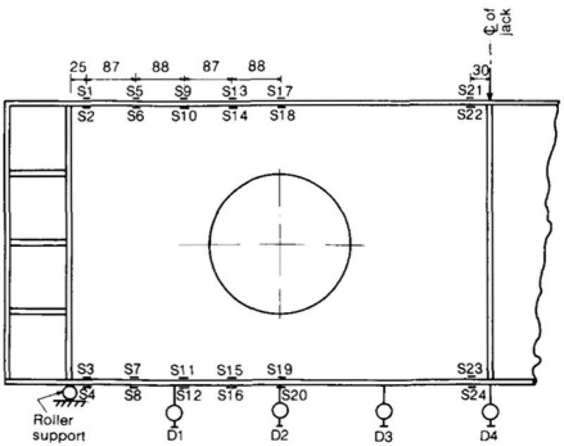
Welding has been utilised to connect the flanges, web, and vertical and horizontal stiffeners of the specimens to each other. The specimens have no translation perpendicular to their axis and their out-of-plane translation has been prevented, too. The specimens have two supports at their ends, which have one and two degrees of freedom. In the tests, the shear loading was applied at the mid-span using a servo-controlled hydraulic jack operated by a Losenhausen control system, which could enable the application of the loads by both the load control or by the deflection control. In the experiments, the deflection control was utilised by an extremely low rate of the deflection increase, so that monitoring of the unloading behaviour of the specimens could be possible. Dial gauges were applied in order to measure the vertical deflection of the flanges and electrical resistance strain gauges were used to monitor the strains developed in the flanges. The positions of the electrical resistance strain gauges and the dial gauges are presented in Fig. (2). In Fig. (2), D and S designate dial gauges and electrical resistance strain gauges, respectively. A Compulog, connected to a high-speed punch, was utilised to monitor the strains at the end of each load increment. The travel of the jack was monitored by the use of a low voltage digital transducer. Small increments of load were used in order to apply the load. The occurred strains in the flanges and the vertical deflection of the PSPGs were also recorded at the end of each load increment. The PSPGs were tested to failure [3].
2.2. Accuracy of Finite Element Modelling
The second step is to verify modelling. To conduct the verification of the modelling, the experimentally tested PSPGs have been simulated accurately. All the components of the tested specimens, including the steel material, loading, and boundary conditions have exactly been modelled taking into account the same features in the tests.
The modelling of the steel material has been performed as its important part. The steel has been assumed to behave as an elastic-perfectly plastic material in both tension and compression. The bilinear kinematic hardening behaviour has been applied for the steel to consider progressive hardening and softening effects [34]. The elastic and the metal plasticity with the plastic option were considered for the material properties of the steel. The Young’s modulus, E, Poisson’s ratio, υ, and yield stress of the steel, fy, are required as input in ABAQUS. The model dimensions and its features were completely adopted from the measured values of the tested specimens. The von Mises and yield functions were considered for the material yielding.
In order to model the steel plates and the stiffeners, the shell element S4R8 has been used. It is a four-node element, in which each node has eight degrees of freedom. This element is perfect where there are large and nonlinear deformations. Also, this element is preferred where the sections comprise of a dimension thinner than other dimensions. Therefore, this element has been applied in this research since the thickness is thinner than other dimensions in the PSPGs. Because of the regular geometry of the PSPGs, the quadrilateral element has been used for the steel plates and the stiffeners, which is an efficient element in such cases. The Newton’s iterative technique has been utilised to extensively analyse the nonlinear behaviour of the PSPGs under the loading.
The two methods of the force or displacement control can be employed in the software for the loading simulation. In the force method, the force is applied to the PSPGs and then its corresponding displacement is obtained. However, in the displacement method, the displacement is applied to the PSPGs, and the force that corresponds to its displacement is achieved. Accordingly, the force method has been used at the mid-span of the PSPGs in this study. The boundary conditions of the tested specimens have completely been modelled through restraining their suitable degrees of freedom.
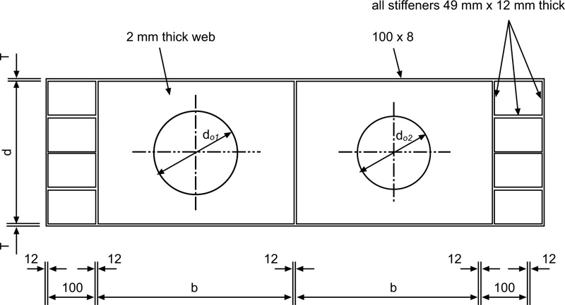
| Experimentally Tested Specimen | Flange | Web | Diameter of Opening | Yield Stress (N/mm2) | ||||
|
Thickness (mm) |
Width (mm) |
b (mm) |
d (mm) |
d01 (mm) |
d02 (mm) |
Flange | Web | |
| PSPG1 | 8 | 100 | 750 | 500 | 350 | 400 | 245 | 230 |
| PSPG2 | 8 | 100 | 750 | 500 | 0 | 50 | 256 | 246 |
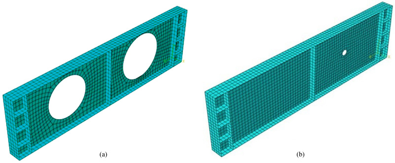
Mesh refinement is an important step in the modelling. After examining different mesh sizes for the modelled PSPGs, finally, the suitable mesh sizes which resulted in more exact results were selected for the nonlinear analysis. Fig. (3) shows the modelled PSPGs after meshing. At last, after considering all the mentioned features in the modelling of the PSPGs, they were analysed nonlinearly applying the ABAQUS software.
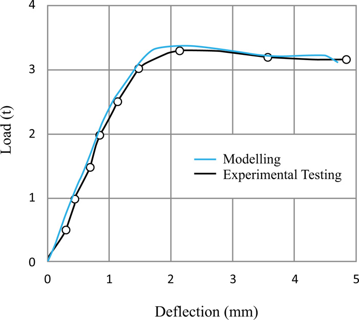
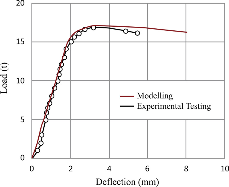
The modelling results obtained from the analysis have been plotted as the load-deflection diagrams. The modelling results are compared with the experimental tests results in order to evaluate the modelling accuracy. As it can be observed from Fig. (4), the simulated PSPG1 could bear the ultimate force of 3.4 t; however, the experimentally tested PSPG1 could carry the ultimate force of 3.35 t, which uncovers that the difference between these ultimate forces is very small. Also, Fig. (5) elaborates similarity of the failure modes of tested and modelled PSPG1s. On the other hand, the obtained ultimate force of the simulated PSPG2 is 17.11 t while it is 16.8 t for the experimentally tested PSPG2, which again reveals a slight difference (1.8%) between these achieved ultimate forces, as shown in Fig. (6).
Moreover, according to Figs. (4 and 6), the behaviours of the modelled and tested PSPGs are similar under the loading. Consequently, these small differences between the ultimate forces and similar behaviours of the modelled and tested PSPGs uncover the accuracy of the modelling and the modelling has been verified. As a conclusion, the proposed 3D modelling in this study is perfectly able to predict the behaviour of the PSPGs accurately.

3. RESULTS AND DISCUSSION
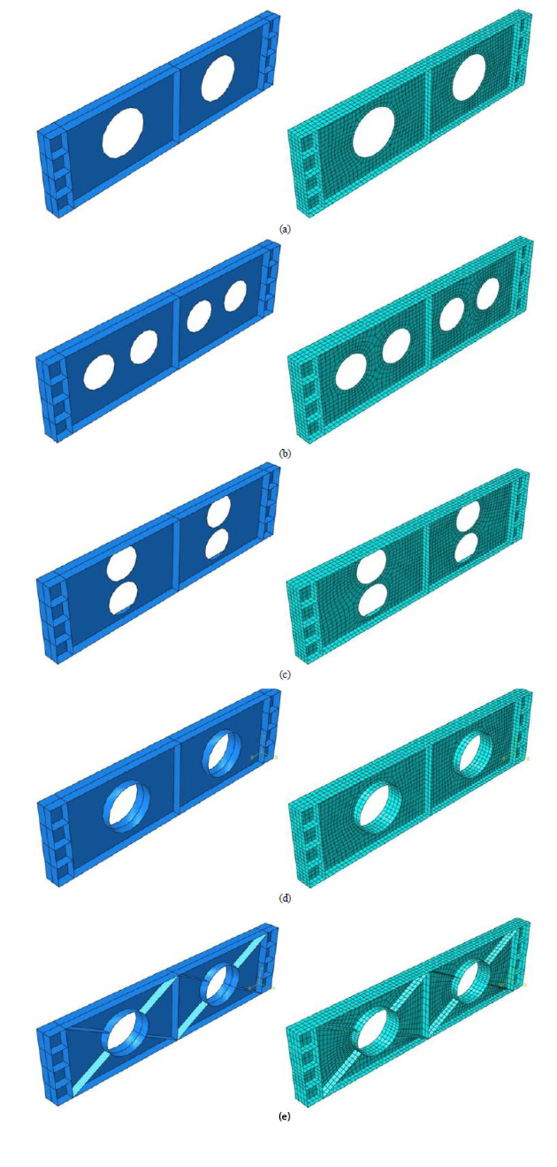
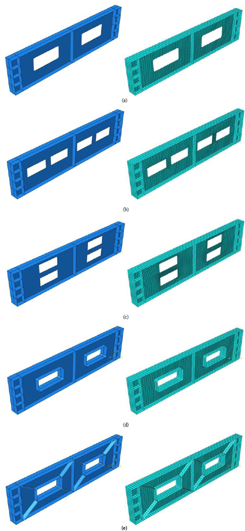
Since the finite element modelling was verified in the previous section, the same method was used for modelling the developed PSPGs to widely assess their behaviour under different conditions, as the third step of this study. Various parameters were adopted in the nonlinear analysis of the PSPGs. The features and obtained ultimate capacities of the analysed PSPGs are listed in Table 2. C and R in the PSPGs labels designate the circular and rectangular shapes of the openings, respectively. The numbers following C and R are the number of the openings on each side of the PSPGs. H and V indicate the horizontal and vertical arrangements of the openings, respectively. F and S respectively present the frame around the openings and stiffeners connecting the openings to the corners of the PSPGs. The numbers after H and/or F are their thicknesses. The diameter, d, of each circular opening is 300 mm. The total area of the openings and the dimensions of the PSPGs are the same. Figs. (7 and 8) illustrate the modelled PSPGs. The parameters in the nonlinear analysis include the shape of the openings (circular and rectangular openings), number of the openings (2 and 4 openings), arrangement of the openings (horizontal and vertical openings), using steel frame around the openings, utilising diagonal steel stiffeners to connect the steel frame to the corners of the PSPGs, and thicknesses (2 mm and 4 mm) of the steel frame and the diagonal steel stiffeners. Meanwhile, the effects of these parameters on the behaviour of the PSPGs are discussed below, as the fourth step of the current study.
3.1. Effects of Shape of Openings
The circular and rectangular openings were adopted to evaluate the effect of shape of the openings on the behaviour of the PSPGs. Table 2 illustrates that the ultimate capacity, fu, achieved for C1H with one circular horizontal opening on each side is 36 kN, which was decreased to 21 kN for R1H by using one rectangular horizontal opening, implying 41.7% reduction of the ultimate capacity. The same process of the ultimate capacity reduction by the change of the circular opening to the rectangular opening can also be noticed for 2 horizontal openings on each side of the PSPGs (C2H and R2H) and for the vertical openings (C2V and R2V). Thus, the circular opening is superior to the rectangular opening. Because the stresses are concentrated on the corners of the rectangular openings, which is not the case in the circular openings. This stresses concentration accelerates the risk of the web buckling of the PSPGs. On the other hand, the shear stresses distribution on the web of the PSPGs with the circular openings is more uniform than that with the rectangular openings, which have four angles. This better distribution of the stresses on the web of the PSPGs with the circular openings leads to their higher ultimate capacities compared with the PSPGs having the rectangular openings. Therefore, the shape of the opening is an important factor in the design of PSPGs.
3.2. Effects of Number of Openings
The PSPGs with 1 and 2 horizontal openings on each side (totally 2 and 4 openings) were considered with the circular and rectangular shapes of the openings to assess the effects of the number of openings on the PSPGs. They were labelled as C1H, C2H, R1H, and R2H. As it can be observed from the obtained values in Table 2, the increase of the number of the web openings from 2 (C1H) to 4 (C2H) decreases their ultimate capacity from 36 kN to 32 kN, a reduction of 11.1%. Consequently, increasing the number of openings reduces the ultimate capacity. Because, as the number of web openings is increased, the web plate area resisting the shear stresses is reduced and the web is weakened, which result in the lower capacity of the PSPGs.
| No. | PSPG Label |
Number of Horizontal Opening on Each Side | Number of Vertical Opening on Each Side |
Frame (mm) |
Stiffener (mm) |
Ultimate Capacity fu (kN) |
|---|---|---|---|---|---|---|
| 1 | C1H | 1 | - | - | - | 36 |
| 2 | C2H | 2 | - | - | - | 32 |
| 3 | C2V | - | 2 | - | - | 23 |
| 4 | C1HF2 | 1 | - | 2 | - | 42 |
| 5 | C1HF2S2 | 1 | - | 2 | 2 | 46 |
| 6 | C1HF2S4 | 1 | - | 2 | 4 | 48 |
| 7 | C1HF4S2 | 1 | - | 4 | 2 | 52 |
| 8 | C1HF4S4 | 1 | - | 4 | 4 | 54 |
| 9 | R1H | 1 | - | - | - | 21 |
| 10 | R2H | 2 | - | - | - | 19 |
| 11 | R2V | - | 2 | - | - | 13 |
| 12 | R1HF2 | 1 | - | 2 | - | 25 |
| 13 | R1HF2S2 | 1 | - | 2 | 2 | 27 |
| 14 | R1HF2S4 | 1 | - | 2 | 4 | 28 |
| 15 | R1HF4S2 | 1 | - | 4 | 2 | 30 |
| 16 | R1HF4S4 | 1 | - | 4 | 4 | 31 |
3.3. Effects of Arrangement of Openings
Vertical as well as horizontal openings with the circular and rectangular shapes were applied to examine the effects of the arrangement of the openings on the behaviour of the PSPGs. The PSPG with the horizontal openings as R2H has the ultimate capacity of 19 kN, while the one with vertical openings, R2V, owns the ultimate capacity of 13 kN, which indicates 31.6% decrease in the ultimate capacity (Table 2). Therefore, the arrangement of the openings considerably affects the behaviour of the PSPGs. The reason is that changing the arrangement of the openings from horizontal to vertical causes the web area between the vertical openings become less than that between the horizontal openings so that this web area between the vertical openings does not significantly prevent the buckling of the web under the shear load and these two close vertical openings behave like a big opening with the total opening area approximately equal to two openings, therefore, the vertical openings have more noticeable effect on weakening the web. Accordingly, most of the shear stresses and deformations occur in the region of the vertical openings, which reduce the ultimate capacity of the PSPGs.
3.4. Effects of Using Steel Frame around Openings
The steel frame was employed around the circular and rectangular openings to assess its effects on the behaviour of PSPGs. Table 2 indicates that using the steel frame for R1H that changes it to R1HF2, improves the ultimate strength from 21 kN to 25 kN, which offers the ultimate capacity enhancement of 19%. As a result, the ultimate capacity is improved by the use of the steel frame around the openings. Utilising the steel frame around the openings increases the stiffness and rigidity of the openings, which delays their buckling. Also, the steel frame strengthens the openings and causes more distribution of the stresses in the web and around the openings frame that leads to higher ultimate strength.
3.5. Effects of Using Diagonal Steel Stiffeners
The effects of using the diagonal steel stiffeners, which connect the frame around the circular and rectangular openings to the corners of the PSPGs, are also evaluated. According to the obtained values in Table 2, the ultimate capacity of the C1HF2 is 42 kN, which increases to 46 kN for C1HF2S2 by using the diagonal steel stiffeners, indicating an increase of 9.5%. Thus, the improvement of the ultimate capacity is accomplished by the use of the steel stiffeners, because the use of the steel stiffeners stiffens the web more and helps prevent buckling of the web. Moreover, the stiffeners make the web stronger and affect the better distribution of the stresses in the web of the PSPGs.
3.6. Effects of Thickness of Steel Frame and Diagonal Steel Stiffeners
The steel frame and diagonal steel stiffeners were also considered with thickness of 4 mm to investigate the effects of the thickness on the PSPGs. As the steel frame thickness of C1HF2S2 increases from 2 mm to 4 mm for C1HF4S2, the ultimate capacity enhances from 46 kN to 52 kN, an improvement of 13%. On the other hand, enhancing the thickness of the diagonal steel stiffeners from 2 mm in C1HF2S2 to 4 mm in C1HF2S4 leads to the ultimate capacity increase from 46 kN to 48 kN, which uncovers 4.3% increase of the ultimate capacity. As a consequence, the enhancement of the steel frame thickness and/or stiffeners increases the ultimate capacity of the PSPGs, because they reinforce the web and distribute the shear stresses in the web even more, which results in the delay of the web buckling. Nevertheless, increasing the steel frame thickness offers more remarkable effect on the enhancement of the ultimate capacity of the PSPGs compared with the stiffeners thickness.
3.7. Failure Modes
The failure modes of the PSPGs, with the circular and rectangular web openings, are presented in Figs. (9 and 10), respectively. The distribution of the shear stresses as the result of the applied load can be witnessed from the figures. Fig. (9) illustrates that utilising the steel frame in C1HF2 and the diagonal steel stiffeners in C1HF2S2, C1HF4S2, and C1HF4S4 causes the PSPGs to carry more loads. The same process can also be observed for the PSPGs with the rectangular openings as R1HF2, R1HF2S2, R1HF2S4, R1HF4S2, and R1HF4S4 in Fig. (10). In addition, formation of plastic hinges in the highly concentrated stresses areas of the webs and flanges of those PSPGs which could withstand larger loads can be seen from Figs. (9 and 10). The presence of the openings has affected the inclination and width of the membrane field, as well. Since the stresses concentration exists at the edge of the openings, the intensity of stresses across the membrane field alters across the openings section.
Therefore, according to the figures, the use of the steel frame around the openings makes the PSPGs stronger, which leads to higher absorption of the stresses. Moreover, utilising the steel stiffeners contributes to the larger stress resistance of the PSPGs web. In conclusion, using the steel frame around the openings and/or steel stiffeners and/or increasing their thickn esses strengthens the PSPGs that lead to resist larger loads.


CONCLUSION
In this paper, the ultimate behaviour of the PSPGs was widely studied under shear loading. The nonlinear analyses of the PSPGs were performed by the use of the finite element software ABAQUS. The verification of the modelling was carried out by comparing the results of the experimental tests on the PSPGs and their modelling. Various nonlinear finite element analyses were thereafter conducted on the developed PSPGs considering different parameters. The parameters included shape of the openings (circular and rectangular openings), number of the openings (2 and 4 openings), arrangement of the openings (horizontal and vertical openings), using steel frame around the openings, utilising diagonal steel stiffeners, and thicknesses (2 mm and 4 mm) of the steel frame and the diagonal steel stiffeners. The ultimate behaviour of the PSPGs was evaluated considering the effects of these parameters. It was found that the shape of the openings significantly affects the PSPGs behaviour and the circular openings are preferred compared with the rectangular ones. Increasing the number of openings has an adverse impact on the ultimate capacity. The ultimate capacity of the PSPGs is considerably influenced by the arrangement of the openings. The use of the steel frame around the openings improves the ultimate capacity. Utilising the steel stiffeners enhances the ultimate capacity. The enhancement of the thickness of the steel frame and/or diagonal steel stiffeners enhances the ultimate strength. However, the increase of the steel frame thickness has more remarkable effect on enhancing the ultimate capacity compared with that of the stiffeners thickness. Failure modes of the PSPGs were indicated.
CONSENT FOR PUBLICATION
Not applicable.
AVAILABILITY OF DATA AND MATERIALS
Not applicable.
FUNDING
None.
CONFLICT OF INTEREST
The authors declare no conflict of interest, financial or otherwise.
ACKNOWLEDGEMENTS
Declared none.

