All published articles of this journal are available on ScienceDirect.

Linear Analysis of Stability of Pitched Roof Frames
Abstract
Background:
In this paper, geometric nonlinear analysis of pitched roof frames was carried out by the stiffness matrix method using stability functions.
Objective:
This study contributes to a better knowledge of the stability of pitched roof frames, not braced, and therefore of the efficiency in their dimensioning.
Method:
At first, the argument of the stability functions was set as 0.01. The stiffness matrix of the frame has been assembled, as well as the nodal load vector of the frame. The boundary conditions (support restraint and wind bracing restraint) were introduced for the reduction of this matrix and the nodal load vector. At this stage, the determinant of the reduced stiffness matrix and the reduced nodal displacement vector are calculated. The argument of the stability functions is incremented by 0.01 and the operations are repeated until the determinant of the reduced stiffness matrix changes sign. The argument of the iteration preceding the sign change of the determinant and corresponding to its positive value is taken and refined by a process described in the paper. The buckling loads of the frame members are determined at this stage.
Results and Conclusion:
The analysis focused on four frames; the obtained results show that the increase in the inclination of the crossbar makes it possible to take full advantage of the “arch effect”. Arch effect is due to the presence of crossbars which have a linear arch shape. Furthermore, the angle as well as the length ratio, between the crossbar and post, influence critical load value.
1. INTRODUCTION
The geometric nonlinear analysis of pitched roof frames will be made by the stiffness matrix method using stability functions. Geometric nonlinear analysis of frames is a problem of elastic instability. Although the structure is in the elastic range, the effects of large displacements (large deformations) modify the geometry of the structure; which renders inapplicable the theory of linear elasticity. Examples of these phenomena of instability are buckling, local buckling and lateral buckling [1].
Stability analysis in solid mechanics began with Euler's solution of buckling of an elastic column (Euler, 1744). Most basic linear elastic problems of structural stability were solved by the end of the 19th century, although further solutions have been appearing as new structural types were being introduced. The twentieth century has witnessed a great expansion of the stability theory into nonlinear behavior, caused either by large deflections or by nonlinearity of the constitutive law of the material [2].
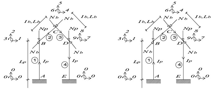
The pitched roof frame type shown in Fig. (1) is probably the structural solution most often used in steel construction, especially for buildings used for industrial, agricultural or sports purposes [3, 4]. The use of pitched roofs naturally leads to the construction of long-span frames (it is quite common to find frames with span-to-height ratios greater than 10). This is mainly due to the fact that the inclination of the cross member makes it possible to take advantage of an “Arch Effect” [5], which noticeably increases the rigidity of the roof and makes possible the transfer of rather high loads with crossbars relatively slender. However, the crossbars can be subjected to significant axial forces (of the same order of magnitude, if not greater, to the forces in the posts [5]), which has a significant influence on the stability and the nonlinear behavior of the frames. This influence is often overlooked, especially because of the traditional reasoning that, because of the relatively low compressive forces present in the posts, one-storey frames are only marginally susceptible to problems of instability [6]. This erroneous notion seems to be confirmed by the fact that most codes relating to metallic structures, in particular, Eurocode 3 [7], contain, so to speak, almost no reference to this phenomenon, which is, however, particularly important.
Arches carry most of their loads by developing compressive stresses within the arch itself and therefore in the past were frequently constructed using materials of high compressive strength and low tensile strength such as masonry. In addition to bridges, arches are used to support roofs. They may be constructed in a variety of geometries; they may be semicircular, parabolic or even linear where the members comprising the arch are straight. Today arches are usually made of steel or of reinforced or prestressed concrete and can support both tensile as well as compressive loads. They are used to support bridge decks and roofs and vary in span from a few metres in a roof support system to several hundred metres in bridges.
Previous research on the stability of pitched roof frames used analytical approaches. As can be seen from the literature, very few analytical studies have been conducted on the stability of this type of frame. This is in part due to the mathematical difficulties that may be involved in the solution of the associated boundary-value problem, imagine that we are faced with the problem of solving a large set of simultaneous differential equations along with a large number of continuity conditions and boundary conditions. It is true that the mathematical difficulties encountered in the analytical study of pitched roof frames can be greatly eased through the use of numerical approaches, such as the stiffness matrix method, along with the support of modern high-performance computers.
The aim of the study is to find the critical loads of the frame members. The determinant of the reduced stiffness matrix of the frame, as well as the argument of the stability functions, are used to determine these critical loads. A computer program is used to carry out the various operations.
2. GEOMETRY, LOADING AND SUPPORT CONDITIONS
This paper is devoted to calculating the critical load of pitched roof frames made up of straight members. The posts of the frame, which are vertical, rise continuously from the foundation to the top of the structure. The posts of the first storey can be of different lengths. The crossbars make an angle α with the horizontal. The bars are connected to the nodes, which are considered non-deformable, by rigid assemblies. The feet of the posts are fixed in a rigid manner to the foundation.
The external forces considered in the present study are such that, before the loss of stability, the members undergo only axial compression (or traction). For example, Fig. (1) shows such a system of forces. Here, the loads are only concentrated loads applied to the nodes, acting in the axes of the posts and crossbars.
To make the analysis of frames easier and systematic, it is useful to introduce some non-dimensional parameters Table 1 concerning the geometry, the loading and the support conditions (stiffness of the posts feet). These parameters are as follows:
| α | Unbraced Frames | |||
|---|---|---|---|---|
| RI | RL | S | RN | |
| 6° | 1 | 2 | 0 | 0,59 |
| 0,95 | ||||
| 3 | 0 | 0,86 | ||
| 1,45 | ||||
| 12° | 1 | 2 | 0 | 0,59 |
| 0,93 | ||||
| 3 | 0 | 0,82 | ||
| 1,30 | ||||
They reflect on the one hand, the ratios that exist between the inertias (RI), the lengths (RL), the axial forces (RN) of the posts and crossbars and, on the other hand, the relative stiffness of the posts feet, calculated in relation to the characteristics of the posts themselves (S) [8].
 |
(1) |
3. ASSUMPTIONS
This study is based on the following assumptions:
- The materials that make up the bars are supposed to be perfectly elastic.
- The nodes are supposed to be rigid.
- Forces are expected to maintain their original direction and initial point of the application during buckling.
- In addition, the external forces are such that, before the loss of stability, the bars undergo only an axial force (compression or traction).
- Deformations (in the displaced state) are considered small.
- The case of buckling studied is that of bending buckling in the plane of the frame. It is assumed that the spatial buckling accompanied by twisting and local buckling of the walls is prevented.
- Secondary bending effects are neglected.
In addition, the elastic length variations due to axial forces are neglected. All the nodes of a crossbar thus have the same transverse displacement.
4. STABILITY STUDY
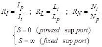
Nonlinear analysis of structures can be formulated using Fig. (2) and Equation 2.
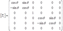
The stiffness matrix ([ki] in local coordinate system) and that of rotation transformation, [Ti], of a member << i >> are modified during the increase of the axial load. However, in this study, [Ti] is assumed unaffected.
 |
(2) |
Where:
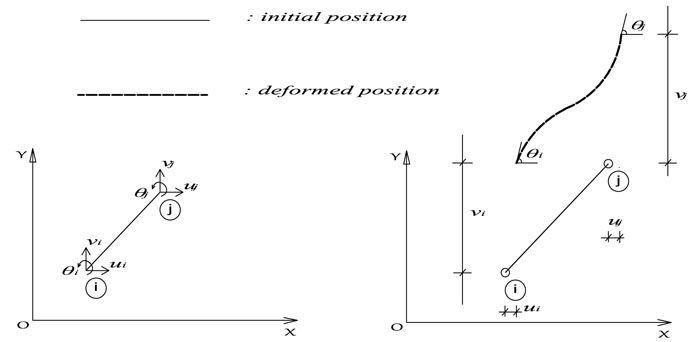
 |
{fi} is the nodal load vector of the member; Pi, Vi and Mi respectively represent axial force, shear force and bending moment at node i.
{di} is the vector of nodal deformations of the member; ui, vi and θi respectively represent axial displacement, lateral displacement and rotation at node i.
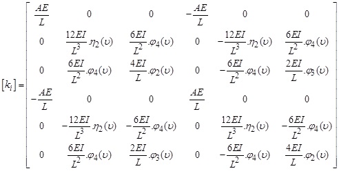 |
E is YOUNG’s modulus of elasticity of the member material, A, the cross-sectional area of a member, I, the moment of inertia of a section, L, the length of a member; φ(υ) and η(υ) are the stability functions.
The stability functions [9] of the members (equation 3) cannot be calculated because the axial forces acting on them are unknown. An iterative method is used to overcome this difficulty. One starts by calculating these functions using as load argument υ = 0.01.
The following steps should be implemented for the linear analysis of the stability of a frame:
- Step 1 Idealize the structure and establish global axes,
- Step 2 Number the nodes (A, B, C, D, ...) and the degrees of freedom (d.o.f.) of the structure (0 for inactive d.o.f., and 1, 2, 3, 4, 5, 6, 7, …, for the others),
- Step 3 Number the members and assign an arrow to each member so that ends i and j are defined,
- Step 4 Enter the geometric characteristics (area, inertia, length) of each member and its orientation angle, θ, as well as the mechanical properties of the materials (YOUNG’s modulus, COULOMB’s modulus),
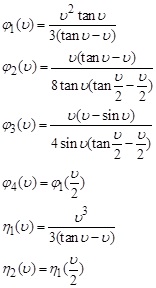 |
(3) |
- Step 5 Initialize the argument υ to 0.01 and the iterations counter << Count. >> to 1,
- Step 6 Enter the expressions of the stability functions and form the stiffness matrix, [ki], and the nodal load vector, {fi}, of each member in the local coordinate system; for uncompressed members,
 |
(4) |
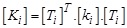
- Step 7 Form the rotation transformation matrix, [Ti], of each member and calculate its stiffness matrix, [Ki], and its nodal load vector, {Fi}, in the global coordinate system,
 |
(5) |
 |
(6) |
- Step 8 Assemble the stiffness matrix, [K], and the nodal load vector, {F}, of the structure,
- Step 9 Form the reduced stiffness matrix, [Kr], and the reduced nodal load vector, {Fr}, of the structure by ignoring the rows and columns corresponding to inactive d.o.f. (restraint of supports and restraint of wind bracing) and of zero order number << 0 >>,
- Step 10 Calculate the reduced nodal deformation vector, {Dr}, of the structure:
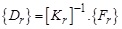 |
(7) |
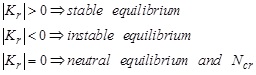
- Step 11 Calculate the determinant of the reduced stiffness matrix, │Kr│,
- If │Kr│ sign changes, go to step 12
- If not, increment υ and Count., and return to step 6:
 |
(8) |
- Step 12 Continue the calculations with the penultimate value of the argument υ, with a small increment (0.001) to improve the accuracy in determining the critical argument, υcr, and therefore, the critical load, Pcr; stop operations as soon as │Kr│ changes sign, and take υ for which │Kr│> 0, as critical argument, υcr.
5. FLOWCHART OF THE COMPUTER PROGRAM
The algorithm required for the linear analysis of stability of pitched roof frames (by stiffness matrix method) is represented in the form of a flowchart Fig. (3) showing the important tasks to be performed.
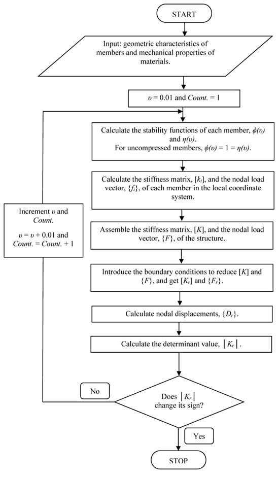
This algorithm is based on the stiffness matrix method. The data input of the program is the geometric characteristics of members and mechanical properties of materials. The displacements, the determinant and the axial forces of the members will be determined for each argument υ, until │Kr│ changed sign.
6. NUMERICAL EXAMPLES
6.1. Example 1
Let's start with a digital application for a basic construction. Let us study the stability of the simple symmetrical frame and symmetrically loaded shown in Fig. (1a) for the numerical values: Lp = 4.00 m, α = 6°, Lb = 8.00 m, A = 331 cm2, Ip = Ib = 18 260 cm4, E = 21 000 kN/cm2, Np = 1 000 kN.
The following Table 2 presents the computation of the determinant │Kr│ and the nodal displacements {Dr} of the frame, for increasing values of υ:
| No. | υ |
Load Np (kN) |
│Kr│ | Nodal Displacements {Dr} of the Frame | |||
|---|---|---|---|---|---|---|---|
| d.o.f. | |||||||
| u (mm) | v (mm) | θ (rad) | |||||
| 1 | 0.01 | 2.40E-01 | 4.44009E+35 | Node A | - | - | - |
| Node B | 2.9425E-04 | -1.3782E-04 | -1.0193E-07 | ||||
| Node C | 1.1346E-04 | -9.1727E-04 | -1.1343E-07 | ||||
| Node D | -6.7393E-05 | -1.3801E-04 | -1.1502E-08 | ||||
| Node E | - | - | - | ||||
| 2 | 0.02 | 9.59E-01 | 4.43601E+35 | Node A | - | - | - |
| Node B | 1.1771E-03 | -5.5129E-04 | -4.0781E-07 | ||||
| Node C | 4.5416E-04 | -3.6711E-03 | -4.5402E-07 | ||||
| Node D | -2.6903E-04 | -5.5204E-04 | -4.6216E-08 | ||||
| Node E | - | - | - | ||||
| . | - | - | - | Node A | - | - | - |
| Node B | - | - | - | ||||
| Node C | - | - | - | ||||
| Node D | - | - | - | ||||
| Node E | - | - | - | ||||
| . | - | - | - | Node A | - | - | - |
| Node B | - | - | - | ||||
| Node C | - | - | - | ||||
| Node D | - | - | - | ||||
| Node E | - | - | - | ||||
| 68 | 0.633 | 9.60E+02 | 1.78121E+32 | Node A | - | - | - |
| Node B | 2.8593E+02 | -8.3989E-01 | -2.6501E-01 | ||||
| Node C | 8.4185E+02 | -5.3205E+03 | -8.1034E-01 | ||||
| Node D | 1.3979E+03 | -2.6533E-01 | -5.4862E-01 | ||||
| Node E | - | - | - | ||||
| 69 | 0.634 | 9.63E+02 | -9.20937E+32 | Node A | - | - | - |
| Node B | -5.4193E+01 | -4.9804E-01 | 5.1043E-02 | ||||
| Node C | -1.6317E+02 | 1.0303E+03 | 1.5705E-01 | ||||
| Node D | -2.7219E+02 | -6.1068E-01 | 1.0665E-01 | ||||
| Node E | - | - | - | ||||
The reduced stiffness matrix of the frame, [Kr], is a function of the load because of the geometrical non-linearity; this is used as a stability criterion:
 |
(9) |
The following Table 3 presents the calculation of some characteristics of the frame:
| Element | Critical Value υcr | Ncr (kN) | λcr | ρ | μ |
|---|---|---|---|---|---|
| Post | 0.633 | 9.60E+02 | 0.960301275 | 0.040598284 | 4.96302157 |
| Beam | 1.234 | 9.12E+02 | 0.960301275 | 0.154273478 | 2.545976346 |
We have:
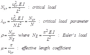 |
(10) |
6.2. Example 2
Now let us consider the same construction as before, for the numerical values: Lp = 4.00 m, α = 12°, Lb = 8.00 m, A = 331 cm2, Ip = Ib = 18 260 cm4, E = 21 000 kN/cm2, Np = 1 000 kN.
The following Table 4 presents the computation of the determinant │Kr│ and the nodal displacements {Dr} of the frame, for increasing values of υ:
| No. | υ |
Load Np (kN) |
│Kr│ | Nodal Displacements {Dr} of the Frame | |||
|---|---|---|---|---|---|---|---|
| d.o.f. | |||||||
| u (mm) | v (mm) | θ (rad) | |||||
| 1 | 0.01 | 2.40E-01 | 8.1462E+35 | Node A | |||
| Node B | 2.0634E-04 | -1.3787E-04 | -8.0221E-08 | ||||
| Node C | 1.1457E-04 | -9.3806E-04 | -1.1454E-07 | ||||
| Node D | 2.2738E-05 | -1.3796E-04 | -3.4315E-08 | ||||
| Node E | |||||||
| 2 | 0.02 | 9.59E-01 | 8.1414E+35 | Node A | |||
| Node B | 8.2530E-04 | -5.5147E-04 | -3.2091E-07 | ||||
| Node C | 4.5845E-04 | -3.7533E-03 | -4.5831E-07 | ||||
| Node D | 9.1350E-05 | -5.5186E-04 | -1.3740E-07 | ||||
| Node E | |||||||
| . | . | . | . | Node A | . | . | . |
| Node B | . | . | . | ||||
| Node C | . | . | . | ||||
| Node D | . | . | . | ||||
| Node E | . | . | . | ||||
| . | . | . | . | Node A | . | . | . |
| Node B | . | . | . | ||||
| Node C | . | . | . | ||||
| Node D | . | . | . | ||||
| Node E | . | . | . | ||||
| 90 | 0.844 | 1.71E+03 | 9.80033E+31 | Node A | |||
| Node B | -1.0202E+03 | -3.5610E+00 | -5.5997E-01 | ||||
| Node C | 3.9077E+03 | -2.3282E+04 | -3.6307E+00 | ||||
| Node D | 8.8389E+03 | 1.5962E+00 | -3.1145E+00 | ||||
| Node E | |||||||
| 91 | 0.845 | 1.71E+03 | -1.12873E+33 | Node A | |||
| Node B | 9.0502E+01 | -7.5971E-01 | 4.8152E-02 | ||||
| Node C | -3.3959E+02 | 2.0213E+03 | 3.1546E-01 | ||||
| Node D | -7.6996E+02 | -1.2098E+00 | 2.7112E-01 | ||||
| Node E | |||||||
The following Table 5 presents the calculation of some characteristics of the frame:
| Element | Critical Value υcr | Ncr (kN) | λcr | ρ | μ |
|---|---|---|---|---|---|
| Post | 0.844 | 1.71E+03 | 1.707202266 | 0.072174727 | 3.722266177 |
| Beam | 1.628 | 1.59E+03 | 1.707202266 | 0.268489983 | 1.92990511 |
6.3. Example 3
Now let us consider the same construction as before, for the numerical values: Lp = 4.00 m, α = 6°, Lb = 12.00 m, A = 331 cm2, Ip = Ib = 18 260 cm4, E = 21 000 kN/cm2, Np = 1 000 kN.
The following Table 6 presents the computation of the determinant │Kr│ and the nodal displacements {Dr} of the frame, for increasing values of υ:
| No. | υ |
Load Np (kN) |
│Kr│ | Nodal Displacements {Dr} of the Frame | |||
|---|---|---|---|---|---|---|---|
| d.o.f. | |||||||
| u (mm) | v (mm) | θ (rad) | |||||
| 1 | 0.01 | 2.40E-01 | 4.897E+34 | Node A | |||
| Node B | 5.3375E-04 | -1.3784E-04 | -2.0286E-07 | ||||
| Node C | 2.4113E-04 | -3.0778E-03 | -3.0138E-07 | ||||
| Node D | -5.1550E-05 | -1.3799E-04 | -3.8238E-08 | ||||
| Node E | |||||||
| 2 | 0.02 | 9.59E-01 | 4.88812E+34 | Node A | |||
| Node B | 2.1346E-03 | -5.5136E-04 | -8.1160E-07 | ||||
| Node C | 9.6575E-04 | -1.2327E-02 | -1.2072E-06 | ||||
| Node D | -2.0338E-04 | -5.5197E-04 | -1.5399E-07 | ||||
| Node E | |||||||
| . | . | . | . | Node A | . | . | . |
| Node B | . | . | . | ||||
| Node C | . | . | . | ||||
| Node D | . | . | . | ||||
| Node E | . | . | . | ||||
| . | . | . | . | Node A | . | . | . |
| Node B | . | . | . | ||||
| Node C | . | . | . | ||||
| Node D | . | . | . | ||||
| Node E | . | . | . | ||||
| 53 | 0.456 | 4.98E+02 | 3.0992E+31 | Node A | |||
| Node B | -1.6532E+02 | -4.5999E-01 | -5.6810E-02 | ||||
| Node C | 5.1541E+02 | -6.5220E+03 | -7.1619E-01 | ||||
| Node D | 1.1963E+03 | -1.1356E-01 | -4.4971E-01 | ||||
| Node E | |||||||
| 54 | 0.457 | 5.01E+02 | -1.30734E+32 | Node A | |||
| Node B | 4.0871E+01 | -2.4648E-01 | 1.3027E-02 | ||||
| Node C | -1.2245E+02 | 1.5496E+03 | 1.7026E-01 | ||||
| Node D | -2.8581E+02 | -3.2959E-01 | 1.0730E-01 | ||||
| Node E | |||||||
The following Table 7 presents the calculation of some characteristics of the frame:
| Element | Critical Value υcr | Ncr (kN) | λcr | ρ | μ |
|---|---|---|---|---|---|
| Post | 0.456 | 4.98E+02 | 0.498344616 | 0.021068322 | 6.889457574 |
| Beam | 1.647 | 7.23E+02 | 0.498344616 | 0.274941597 | 1.9071277 |
6.4. Example 4
Now let us consider the same construction as before, for the numerical values: Lp = 4.00 m, α = 12°, Lb = 12.00 m, A = 331 cm2, Ip = Ib = 18 260 cm4, E = 21 000 kN/cm2, Np = 1 000 kN.
The following Table 8 presents the computation of the determinant │Kr│ and the nodal displacements {Dr} of the frame, for increasing values of υ:
| No. | υ |
Load Np (kN) |
│Kr│ | Nodal Displacements {Dr} of the Frame | |||
|---|---|---|---|---|---|---|---|
| d.o.f. | |||||||
| u (mm) | v (mm) | θ (rad) | |||||
| 1 | 0.01 | 2.40E-01 | 1.18356E+35 | Node A | |||
| Node B | 2.7255E-04 | -1.3789E-04 | -1.1368E-07 | ||||
| Node C | 1.6928E-04 | -2.2363E-03 | -2.1157E-07 | ||||
| Node D | 6.5957E-05 | -1.3794E-04 | -5.5573E-08 | ||||
| Node E | |||||||
| 2 | 0.02 | 9.59E-01 | 1.18246E+35 | Node A | |||
| Node B | 1.0897E-03 | -5.5155E-04 | -4.5464E-07 | ||||
| Node C | 6.7740E-04 | -8.9490E-03 | -8.4674E-07 | ||||
| Node D | 2.6492E-04 | -5.5177E-04 | -2.2265E-07 | ||||
| Node E | |||||||
| . | . | . | . | Node A | . | . | . |
| Node B | . | . | . | ||||
| Node C | . | . | . | ||||
| Node D | . | . | . | ||||
| Node E | . | . | . | ||||
| . | . | . | . | Node A | . | . | . |
| Node B | . | . | . | ||||
| Node C | . | . | . | ||||
| Node D | . | . | . | ||||
| Node E | . | . | . | ||||
| 74 | 0.711 | 1.21E+03 | 1.15435E+32 | Node A | |||
| Node B | -5.5922E+02 | -9.0547E-01 | 1.1882E-01 | ||||
| Node C | 2.6766E+02 | -3.9220E+03 | -4.8069E-01 | ||||
| Node D | 1.0949E+03 | -4.8891E-01 | -3.7528E-01 | ||||
| Node E | |||||||
| 75 | 0.712 | 1.21E+03 | -4.56023E+31 | Node A | |||
| Node B | 1.4249E+03 | -1.7004E-01 | -3.0402E-01 | ||||
| Node C | -6.7598E+02 | 9.9162E+03 | 1.2167E+00 | ||||
| Node D | -2.7778E+03 | -1.2283E+00 | 9.5163E-01 | ||||
| Node E | |||||||
The following Table 9 presents the calculation of some characteristics of the frame:
| Element | Critical Value υcr | Ncr (kN) | λcr | ρ | μ |
|---|---|---|---|---|---|
| Post | 0.711 | 1.21E+03 | 1.211544267 | 0.051219986 | 4.418555068 |
| Beam | 2.432 | 1.58E+03 | 1.211544267 | 0.599273837 | 1.291776385 |
7. ANALYSIS OF THE RESULTS
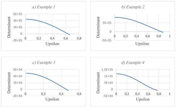
Fig. (4) shows the variation of the determinant of reduced stiffness matrix of the structure according to the upsilon argument for the four previously studied structures.
The following Tables 10, 11 summarize the obtained critical load values for the four previous examples:
| Beam Inclination (α) | RL | RN | Post | Beam | ||
|---|---|---|---|---|---|---|
| Ncr (kN) | Ratio | Ncr (kN) | Ratio | |||
| 6° | 2 | 0,95 | 9,60E+02 | 1,9277 | 9,12E+02 | 1,2614 |
| 3 | 1,45 | 4,98E+02 | 7,23E+02 | |||
| 12° | 2 | 0,93 | 1,71E+03 | 1,4132 | 1,59E+03 | 1,0063 |
| 3 | 1,30 | 1,21E+03 | 1,58E+03 | |||
| Beam Inclination (α) | RL | RN | Post | Beam | ||
|---|---|---|---|---|---|---|
| Ncr (kN) | Ratio | Ncr (kN) | Ratio | |||
| 6° | 2 | 0,95 | 9,60E+02 | 0,5614 | 9,12E+02 | 0,5736 |
| 12° | 0,93 | 1,71E+03 | 1,59E+03 | |||
| 6° | 3 | 1,45 | 4,98E+02 | 0,4116 | 7,23E+02 | 0,4576 |
| 12° | 1,30 | 1,21E+03 | 1,58E+03 | |||
Analysis of the table reveals that the cross member is more compressed than the post (RN > 1) when RL > 2; when RL is fixed, increasing the inclination of the crossbar (α) increases the value of the critical load Ncr (lower sensitivity to elastic instability phenomena); on the other hand, when α is fixed, the increase in the length ratio, RL, reduces the value of the critical load Ncr (high sensitivity to the phenomena of elastic instability).
CONCLUSION
In this paper, we presented a simple and fast method for the linear analysis of stability of pitched roof frames, using stability functions, and updating the stiffness matrix of the structure at each iteration. The reduced stiffness matrix determinant, │Kr│, and the stability function argument, υ, were used to check the singularity condition of the reduced stiffness matrix, [Kr], and the iterations were stopped when │Kr│ changed sign. At this stage, the critical load and some parameters related to it have been determined.
An important event observed during the analysis was that starting from the first iteration, i.e. “υ = 0.01”, the determinant │Kr│ was positive until υcr Fig. (4); which reflects the stability of the structure for loads N < Ncr. Furthermore, the determinant decreased and the displacements converged to infinity (the structure went into an elastically unstable condition) until υcr.
The analysis focused on four frames; the obtained results show that the increase in the inclination of the crossbar (α) makes it possible to take full advantage of the “arch effect”, and that the angle α as well as the length ratio, RL, influence the value of the critical load, Ncr.
LIST OF ABBREVIATIONS
| A | = Cross-sectional area of a member (cm2) |
| d.o.f. | = Degree of freedom |
| {d} | = Vector of nodal deformations |
| {D} | = Vector of nodal deformations of the structure |
| E | = YOUNG’s modulus of elasticity (kN/cm2) |
| {F} | = Structural nodal load vector |
| {f} and {F} | = Nodal load vectors |
| G | = COULOMB’s modulus of elasticity (kN/cm2) |
| I | = Moment of inertia of a section (cm4) |
| [K] | = Structural stiffness matrix |
| L | = Length of a Member (cm) |
| M | = Bending moment |
| N | = Axial force |
| P.R. | = Pitched roof |
| [T] | = Rotation transformation matrix |
| u | = Axial displacement |
| v | = lateral displacement |
| V | = Shear force |
| Greek Symbols | |
| θ | = Rotation (positive counter-clockwise) |
| μ | = Effective length coefficient |
| υ | = Argument of stability functions |
| φ(υ) and η(υ) | = Stability functions |
| Subscripts and Superscripts | |
| b | = Beam |
| cr | = Critical |
| i | = Member index, node index |
| p | = post |
| r | = Reduced |
| T | = Transpose of a matrix |
CONSENT FOR PUBLICATION
Not applicable.
CONFLICT OF INTEREST
The authors declare no conflict of interest, financial or otherwise.
ACKNOWLEDGEMENTS
Declared none.

