All published articles of this journal are available on ScienceDirect.

The Influence of CFRP Orientation Angle on the Shear Strength of RC Beams
Abstract
Background:
Carbon Fiber Reinforced Polymer (CFRP) sheets are widely used for strengthening and repairing reinforced concrete structures. Previous experimental studies have shown that strengthening Reinforced Concrete (RC) beams with CFRP sheet can be greatly influenced by the configuration, orientation and properties of the CFRP sheets.
Objective:
The behaviour of RC beams, strengthened with 60° and 45° inclined CFRP sheets, has not clearly explained.
Method:
Thus, an experimental program, proposed in this paper, investigates the shear behaviour of RC beams strengthened with CFRP sheets under different orientation angles including 0˚, 45˚, 60˚ and 90˚.
Result:
The study shows that strengthening RC beams with CFRP is highly influenced by the orientation angle of the sheets. The influence of CFRP sheets is remarkable on increasing the ultimate deflection, ductility and shear strength of RC beams.
Conclusion:
It is beneficial to strengthen RC beams, which are weak in shear, obliquely using 45˚ or 60˚ inclined CFRP sheets.
1. INTRODUCTION
Fiber Reinforced Polymer (FRP) composites are widely used for strengthening concrete structures due to their corrosion resistance, durability and flexibility [1] compared to other traditional ones such as steel plates. CFRP sheets are used for strengthening and repairing reinforced concrete structures [2]. A great deal of research has been carried out into the shear performance of reinforced concrete beams strengthened with externally FRP composites. Previous experimental studies have shown that strengthening RC beams with CFRP sheet can be greatly influenced by the configuration, orientation and properties of the CFRP sheets [3-14]. Previous tests have shown that CFRP sheets can enhance the strength of existing concrete beams [3-16]. Shear enhancement and failure mode are related to the carbon sheet orientation [3, 4]. If CFRP sheets were wrapped perpendicular to cracks in the beam, a large increase in strength was observed while a brittle behaviour is detected [4]. Previous research showed that the shear strength of beams was significantly increased by the CFRP sheets when the sheets were oriented at 45˚ to the axis of the beam [3]. Other experimental research showed that if CFRP sheets were placed obliquely at an angle of 45˚ to the cracks, a smaller increment in the strength was observed, while failure mode was more ductile [4].
2. LITERATURE REVIEW
Previous experimental research showed that externally adhesive bonded CFRP sheets are effective in strengthening RC beams in shear [5]. Furthermore, a direct relationship was observed between the strength and the number of sheet layers and the depth of sheets across the beam section [5]. Grande et al., observed that using FRP can vary the cracking pattern, the deformation levels and the shear strength of reinforced concrete beams [6]. Abdalla et al. observed that the shear capacity of the strengthened beams increased in a range of 24%-89% as compared to the un-strengthened beam [7]. Chaallal et al. found that using epoxy-bonded strips is beneficial in restoring or increasing the load-carrying capacity of RC beams in shear and in reducing shear cracking [8]. Abdel-Jaber et al. reported that the increment in shear strength due to the presence of CFRP strips is between 19% and 56% [9]. Other experimental studies found that the retrofitted beams exhibit an increase in flexural strength of 18% to 20% for single layer, 40% to 45% for two layers and 68% to 70% for three layers [10].
Al-Ghanem et al. found that the presence of CFRP sheets and laminates can enhance shear and flexural capacity of deep beams. They reported that strengthening RC beams with CFRP sheets increased the shear strength to about 86% compared only to 36% with the inclined laminates [11]. Triantafillou tested eleven reinforced concrete beams strengthened in shear with CFRP at various area fractions and fiber configurations. It is shown that the efficiency of the strengthening technique increased almost linearly with the FRP axial rigidity and reached a maximum, beyond which it varied very little [12]. The experimental results conducted by Abdel-Jaber et al. showed that using CFRP plates can significantly increase the shear strength in beams to a range between 19 to 122% compared to the control beam [13]. Zhang et al. reported that strengthening reinforced concrete beams with CFRP can significantly increase their serviceability, ductility, and ultimate shear strength [17]. Further research is required to investigate the behaviour of RC beams strengthened using CFRP sheets under more different orientation angles.
3. RESEARCH SIGNIFICANCE
Previous experimental studies have shown that CFRP sheets are effective on enhancing the shear strength of existing RC beams while the enhancement significantly depends on the carbon sheet orientation [4]. The 45˚ inclined CFRP sheets increased the ductility of RC beams significantly while it had minor effect on their shear strength [4]. The 90˚ inclined CFRP sheets increased the shear strength of RC beams [4]. The behaviour of RC beams, strengthened with 60˚ and 45˚ inclined CFRP sheets, has not clearly explained in the literature. Therefore, this experimental research investigates the shear behaviour of RC beams strengthened with CFRP sheets under different orientation angles of 0˚, 45˚, 60˚ and 90˚ to the beam longitudinal axis.
4. EXPERIMENTAL PROGRAM
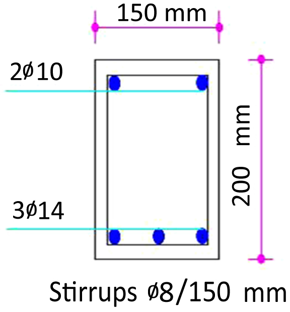
Five simply supported RC beams with a rectangular cross-section of 150 mm by 200 mm were tested. Each beam is 2 m long. The specimens were designed to promote shear failure by choosing small stirrups diameter of 8 mm and the spacing between the stirrups was kept to 150 mm. The details of the test specimens are shown in Fig. (1) where two longitudinal bars No.10 were provided at the top and three longitudinal bars No.14 were provided at the bottom of each beam. The yield strength of the reinforcement bars and the stirrups was 500 MPa and 280 MPa respectively. The corresponding failure load of the beams is between 88 kN and 103 kN. The control beam S-C was not strengthened with CFRP sheets while the other beams were strengthened under different arrangements of CFRP sheets. All beams were cast from the same concrete mix which had a 28 day mean compressive strength of 30 MPa.
4.1. CFRP Properties
The CFRP sheet is 0.166 mm thick. The elastic modulus of the carbon fibers is 230 GPa and the ultimate tensile strength is 4900 MPa. Fiber weight is 300 g/m2, the sheet width is 500 mm and the elongation at break is 2.1%. An epoxy resin was used in conjunction with CFRP sheet which can produce a high performance composite system for use in structural strengthening and upgrade. The mixed density of the epoxy is 1.06 kg/ Lt, the bond strength is greater than 2.5 MPa and it needs 7 days for full cure at 20˚ C.
4.2. Strengthening Scheme
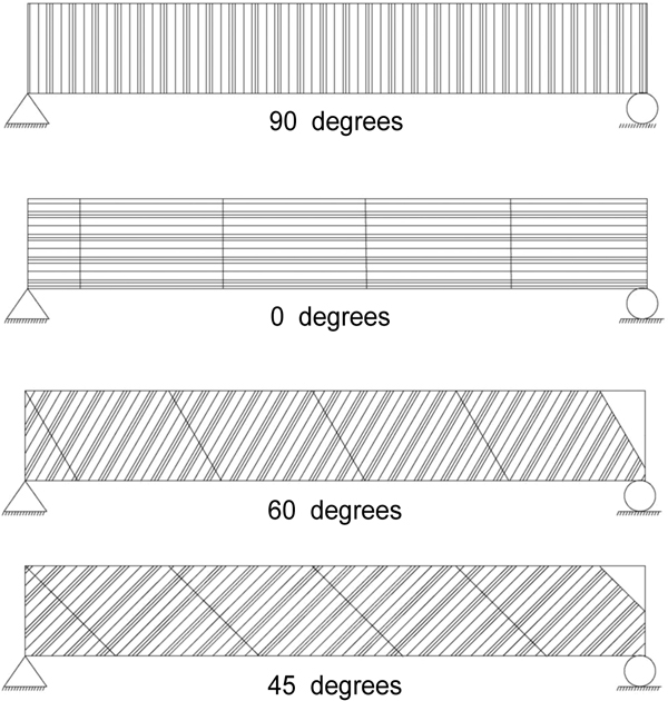
Fig. (2) illustrates strengthening configuration scheme of the tested beams. Furthermore, Figs. (3 to 6) shows the strengthening details of the tested RC beams using CFRP sheets under different orientation angles. The beam surfaces were cleaned of loose particles before strengthening. Specimens S-45 and S-60 were wrapped obliquely using CFRP sheets inducing angles of ± 45˚ and ± 60˚ respectively to the longitudinal axis of the beam as shown in Figs. (3 and 4). Specimen S-90 was wrapped with CFRP sheets from the two sides and the bottom surface where the sheets were attached perpendicular to the longitudinal axis of the beam as shown in Fig. (5). Specimen S-0 was wrapped from its sides and the bottom surface with CFRP sheet fixed parallel to the longitudinal axis of the beam as shown in (Fig. 6).
4.3. Test Setup
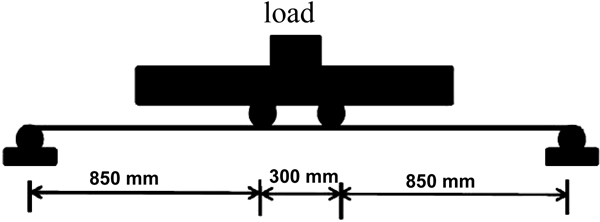
Five full scale beams with different configurations of CFRP were tested. Each beam was simply supported and loaded with two concentrated point loads where the distance between the support and the loading point was kept to 850 mm and the distance between the two concentrated loads was 300 mm, as shown in Fig. (7). A hydraulic jack of 1000 kN capacity was used to apply the loads via rigid steel plate that transferred the loads into two rigid steel cylinders fixed at the loading points as shown in Fig. (7). The hydraulic jack was connected to a rigid steel frame. The test specimens were supported on two rigid steel cylinders, connected to two rigid steel plates that fixed to a rigid support base, representing simply supported reaction where horizontal translation is permitted at one end only. The vertical displacement was measured at mid-span using Linear Variable Displacement Transducers (LVDT).
5. EXPERIMENTAL RESULTS AND DISCUSSION
Ductility is an important factor for any structural element especially in the seismic regions. Ductile elements experience large deformation before failure. Ductility can be estimated using the displacement ductility index (ultimate displacement/yield displacement. Kwan et al. [18] proposed that the ultimate displacement in the ductility index to be taken as the displacement at which the load, after reaching the peak, dropped to 0.8 of the peak load. Furthermore, the yield displacement should be taken as the displacement at 0.75 of the peak load divided by 0.75). Table 1 shows the displacement ductility index of all test specimens with different CFRP configurations.
| Beam | Ductility Index |
|---|---|
| SC | 1.44 |
| S0 | 1.57 |
| S90 | 1.75 |
| S45 | 6.0 |
| S60 | 1.8 |
The experimental results indicate that strengthening RC beams with CFRP sheets is highly influenced by the orientation angle of the CFRP sheets. The effect of CFRP sheets was remarkable on increasing the ultimate deflection, ductility and shear strength of RC beams.
5.1. The Experimental Behaviour of Test Specimens
5.1.1. Control Specimen S-C
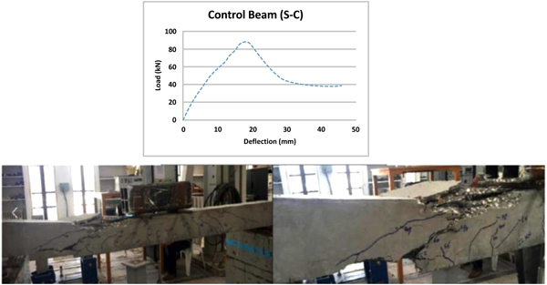
Of the five beams tested, S-C was a control beam which was not strengthened. Beam SC failed at a total load of 88 kN and at a maximum deflection of 44 mm as a result of shear failure as shown in Fig. (8). The first crack appeared at a load of 22 kN. The presence of CFRP sheets with different orientations was found to alter the ultimate load and ductility from that obtained in the control beam. The beam after failure is shown in (Fig. 8).
5.1.2. Specimen S-0
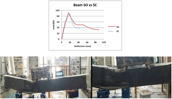
Beam S0 was strengthened with CFRP sheets oriented parallel to the longitudinal axis of the beam and was fully wrapped from its three sides as shown in Fig. (6). The beam failed due to shear at a total load of 93 kN and at a maximum deflection of 94 mm, where the maximum load is 5% greater than that detected in the control beam and the maximum displacement is 51% greater than that measured in the control beam as shown in Fig. (9). The strengthened beam was more ductile with displacement ductility index of 1.57 which is 9% greater than that found in the control beam. The presence of CFRP sheets increased the stiffness of the RC beam as shown in Fig. (9) and postponed the appearance of the first crack to 72 kN. The ultimate deflection is almost double that obtained in the control beam. The beam after failure is shown in Fig. (9) where de-bonding of the CFRP sheet was observed on both sides of the beam after the formation of the diagonal shear crack between the load point and the carbon sheet.
5.1.3. Specimen S-90
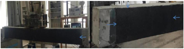
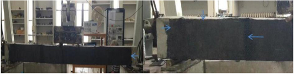
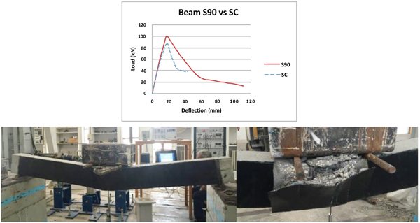
Beam S-90 was wrapped with CFRP sheets oriented perpendicular to the beam longitudinal axis from its three sides as shown in Fig. (5). The maximum load which the beam sustained before shear failure was 100 kN and the maximum deflection was 112 mm as shown in Fig. (10). Shear failure and de-bonding of the CFRP sheets were observed after the formation of a major diagonal shear crack between the load point and the carbon sheet on both sides of the beam as shown in Fig. (10). The influence of CFRP sheets was remarkable on increasing the beam ductility where the displacement ductility index is 21% greater than that in the un-strengthened beam. Furthermore, the maximum deflection is 59% greater than that measured in the control beam. In addition, the influence of CFRP was adequate on increasing the beam strength as shown in Fig. (10) where the maximum load is 12% greater than that detected in the control beam S-C. The influence of CFRP was also obvious on postponing the appearance of the first crack that firstly appeared at 78 kN.
5.1.4. Specimen S-60
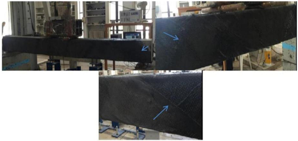
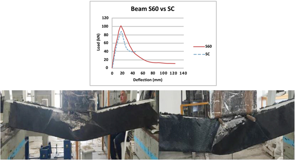
Beam S-60 was strengthened obliquely using CFRP sheets oriented 60˚ to the beam axis and wrapped from its three sides as shown in Fig. (4). The 60˚ angled CFRP sheets had significant effect on enhancing the beam strength and stiffness. Beam S-60 had the best performance compared to the other beams where shear failure occurred at the highest load and greatest deflection as shown in Fig. (11) but it was less ductile than beam S-45. The 60˚ inclined CFRP sheets increased the ductility of the RC beam where the displacement ductility index of the strengthened beam is 25% greater than that found in the control beam. Furthermore, the maximum deflection of the beam was 124 mm which is 62% greater than that measured in the control beam. The beam failed due to shear at a load of 103 kN as shown in Fig. (11). De-bonding of the CFRP sheets was observed on both sides of the beam. The maximum load at failure is 14% greater than that measured in the control beam and the maximum displacement is 63% greater than that obtained in the control beam. The presence of CFRP postponed the appearance of the first crack which firstly appeared at 78 kN.
5.1.5. Specimen S-45
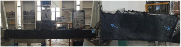
Beam S-45 was strengthened obliquely using CFRP sheets inducing 45˚ to the beam longitudinal axis. The beam was fully wrapped rather than being side wrapped as shown in Fig. (3). The presence of the inclined CFRP enhanced the shear strength and ductility of the beam where the beam failed due to shear at a load of 91 kN and at a maximum deflection of 109 mm as shown in Fig. (12). The ductility of this specimen was increased significantly due to the 45˚ inclined CFRP where the displacement ductility index is four times greater than that found in the un-strengthened beam. Furthermore, the maximum deflection is 58% greater than that measured in the control beam. The beam strength increased slightly by 3% due to the presence of the 45˚ inclined CFRP compared to the control beam.
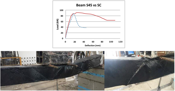
De-bonding of the CFRP sheets was detected on one side of the beam between the concentrated load and the carbon sheet after the propagation of the diagonal shear crack as shown in Fig. (12). The first crack appeared at 67 kN. The presence of the 45˚ inclined CFRP sheets postponed the appearance and propagation of the diagonal shear crack and hence enhanced the response by delaying the load from degradation.
5.2. Effect of CFRP Orientation Angle
Eurocode-2 introduces the strut inclination method for checking shear capacity. It is assumed in this method that shear is resisted by a truss consisting of concrete struts acting in compression
The magnitude of concrete shear strength at the ultimate state is influenced by a combination of five mechanisms activated after the formation of diagonal cracks including shear stresses in un-cracked compressed concrete, aggregate interlock, dowel action of the longitudinal reinforcing bars, arch action and residual tensile stresses transmitted directly across the cracks [20]. The contribution of the shear reinforcement to the shear capacity depends on the maximum stress that the reinforcement can attain.
The ±45˚ inclined CFRP is perpendicular to the angle of the diagonal shear cracks as a result this can promote aggregate interlock, reduce the width of shear cracks, and hence improve the ductility of the beams and postpone cracks propagation. Furthermore, large strains are generally mobilized in the strengthened beams due to the properties of CFRP sheets that increase the tensile stresses in RC beams. By contrast, the diagonal shear cracks in the un-strengthened beam continue propagating and the width of cracks keeps widening without any enhancement. Therefore, the 45˚ oriented CFRP had the best influence on increasing the ductility of the beams as shown in Figs. (12 and 13) followed by the ±60˚ inclined CFRP.
The specimen that strengthened with the 45˚ inclined CFRP failed in a ductile manner and had the highest ductility index compared to the other specimens. The ductility of S-45 was four times greater than that measured in the un-strengthened beam. The 45˚ inclined CFRP significantly increased the ultimate deflection (almost 58%) of the specimen while smaller increments were found in strength and stiffness under this configuration.
The 60˚ inclined CFRP had the most significant influence on increasing the specimen ultimate deflection and shear strength compared to all other specimens. The increments in load and deflection were 14% and 62% respectively. The ductility of specimen S-60 was less than that obtained in S-45 while it was greater than that found in the control beam by 25%.
Longitudinal CFRP (90˚) increased the strength and ductility of RC beams by 12% and 21% respectively compared to the un-strengthened beam. The vertical CFRP sheet had significant effect on increasing the deflection of the specimen due to CFRP tensile properties. The ultimate deflection in S-90 was 59% greater than that in the un-strengthened beam. On the other hand, the effect of transverse CFRP (0˚) was not remarkable on strength and ductility compared to the longitudinal CFRP. Transverse CFRP increased the specimen ultimate deflection by 51% compared to the control beam. In addition, strength and ductility in beam S-0 was 5% and 9% greater than that in the control beam respectively.
5.3. Beam shear strength
Khalifa et al. [21-23] and Triantafillou and Antonopoulos [24] proposed an empirical design equation to predict the shear strength of RC beams strengthened with CFRP. This empirical equation is adopted in the design guidelines of the current American Concrete Institute (ACI) code [25] for strengthening RC beams in shear with CFRP. The nominal shear strength ‘Vn’ is calculated as shown in Equation-1 where ‘Vc’ is the concrete shear strength, ‘ Vs’ is the transverse reinforcement shear strength and ‘Vf’ is the shear strength of external FRP composites.
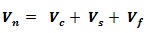 |
(1) |
The shear contribution of concrete and reinforcement is calculated based on ACI code guidelines. The shear contribution of FRP is predicted using Equation2 proposed by Triantafillou.
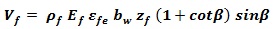 |
(2) |
Where,
pf is the FRP shear reinforcement ratio,

tf is the sheet thickness
Wf is the sheet width
bw is the beam width
Sf is the spacing of the FRP strips which equals >Wf for continuous sheets of vertically oriented FRP
Ef is the elastic modulus of the FRP.
zf is the effective depth of FRP reinforcement measured from the centre of the tensile steel, zf = df
β is the fiber orientation angle with respect to the longitudinal axis of the beam
εfe is the effective strain, εfe = R εfe
εfu is the ultimate tensile strain of FRP.
R is a reduction factor.
Khalifa et al. considered Ras the least of
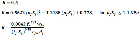
Where,
pfEf is the axial rigidity
wfe is the effective width of the CFRP sheet, Wfe = df - nLe
Le is the effective bond length,
n = 1 for U wrap and 2 for side wrap.
The experimental results of all test specimens are summarised in Table 2. In addition, Table 2 compares between the experimental and predicted beam shear strengths where the shear strengths of concrete and stirrups were calculated based on the guidelines of the ACI code and fiber shear strength contribution was predicted by Khalifa et al. [18-20] empirical model. The predicted shear strength of the un-strengthened beam, obtained using the ACI code, is very close to the experimental value. The predicted shear strengths of the other strengthened beams depend significantly on the orientation angle of the CFRP sheet. Fiber shear strength in specimen S-0, calculated based on Equation 2, is negligible because its orientation angle is zero and sin(zero) equals zero. The predicted shear strengths of the other strengthened specimens are greater than the experimental strengths which mean that Khalifa model overestimates the fiber shear strength.
| Specimen | Ultimate load (kN) | Ultimate deflection (mm) | Ductility index | Experimental shear strength)kN) | Predicted shear strength)kN) | Load at first crack (kN) |
|---|---|---|---|---|---|---|
| S-C | 88 | 44 | 1.44 | 44.7 | 49.7 | 22 |
| S-0 | 93 | 94 | 1.57 | 47.2 | 49.7 | 72 |
| S-90 | 100 | 112 | 1.75 | 50.7 | 91.7 | 78 |
| S-45 | 91 | 109 | 6 | 46.2 | 108.9 | 67 |
| S-60 | 103 | 124 | 1.8 | 52.2 | 107 | 78 |
5.4. Load-deflection Curve
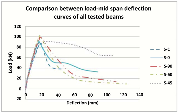
Fig. (13) compares between the load-deflection curves of all beams. In addition, Table 2 summarises the ultimate loads, deflection and ductility indices for all test specimens. All strengthened beams were stiffer than the un-strengthened beam. Furthermore, strengthened beams experienced greater deflections than the un-strengthened beam. The highest load and deflection were found in specimen S-60 which was 14% and 62% greater than that obtained in the control beam respectively. The greatest ductility index was measured in specimen S-45 which is almost 4 times greater than that found in the un-strengthened beam. Specimen S-45 failed in a ductile manner while other specimens were brittle and hence the load degradation in beam S-45 was remarkably low.
CONCLUSION
An experimental program proposed to investigate the shear behaviour of RC beams strengthened with CFRP sheets under different configurations and orientation angles. The beams were strengthened using CFRP sheets oriented at 0˚, 45˚, 60˚and 90˚to the longitudinal axis of the beam. Based on the experimental test results, the following conclusions can be made:
- CFRP sheets can be used effectively to strengthen reinforced concrete beams. Strengthening RC beams with CFRP sheets increase the strength and stiffness of the beams.
- Strengthening RC beams with CFRP sheets is highly influenced by the orientation angle of CFRP sheets. The increments in strength, stiffness and ductility due to CFRP sheets significantly depend on the orientation angle of the sheet.
- The ultimate deflection can be significantly increased in RC beams strengthened with CFRP sheets under any orientation angle due to the properties of the sheet. The ultimate deflection in the strengthened beams is almost double that measured in the control beam.
- CFRP sheets can increase the ductility of RC beams while this increment depends significantly on the orientation angle. The 45˚ oriented CFRP sheets had the best influence on increasing the beam ductility with a smaller increment in the strength.
- The presence of 45˚ inclined CFRP can change the type of failure in RC beam from brittle to ductile. Specimen S-45, strengthened with 45˚ inclined CFRP, failed in a ductile manner while brittle failure was detected in other specimens. S-45 had the highest ductility index compared to other specimens which was four times greater than that measured in the un-strengthened beam.
- The ±45˚ inclined CFRP sheet is perpendicular to the angle of the diagonal shear cracks as a result this can promote aggregate interlock, reduce the width of shear cracks, and hence improves the ductility of the beams and postpone cracks propagation.
- The 60˚ inclined CFRP had the most significant influence on increasing the specimen ultimate deflection and shear strength compared to all other specimens. The increments in load and deflection were 14% and 62% respectively. The ductility of specimen S-60 was less than that obtained in specimen S-45 while it was greater than that found in the control beam by 25%.
- Longitudinal CFRP (90˚) increased the strength and ductility of RC beams by 12% and 21% respectively compared to the un-strengthened beam. The effect of transverse CFRP (0˚) was not remarkable compared to the longitudinal CFRP while the effect was adequate compared to the control beam.
- CFRP sheets can postpone the appearance and propagation of cracks in RC beams.
- It is beneficial to strengthen RC beams using inclined CFRP sheets oriented 45 and 60 degrees to the longitudinal axis of the beam.
CONSENT FOR PUBLICATION
Not applicable.
CONFLICT OF INTEREST
The author declares no conflict of interest, financial or otherwise.
ACKNOWLEDGEMENTS
Declared none.

