All published articles of this journal are available on ScienceDirect.

Ultimate Performance of External End-plate Bolted Joints Under Column Loss Scenario Accounting for the Influence of the Transverse Beam
Abstract
Background:
Steel beam-to-column joints are generally designed and analysed considering the response parame-ters in their main bending plane, disregarding the influence of the connections and the related beams in the transverse direction. However, the 3D response of the joint can be influenced by the presence of the transverse beams in the case of column loss scenario.
Objective:
The objective of the study is to investigate the influence both the influence of the transverse beams and the potential effectiveness of the design rules developed within the research project EQUALJOINTS in case of column loss scenarios.
Method:
A comprehensive set of parametric finite element analyses was carried out. Three external joints were selected, and two types of column loss scenarios were investigated for 2D and 3D joint configurations.
Results:
The obtained results show that the presence of the secondary beams is beneficial to arrest the progressive collapse since it increases the resistance of the joint assembly, reducing the plastic demand into the primary moment-resisting joint.
Conclusion:
The presence of the secondary beams improves the joint performance under column loss thanks to their torsional stiffness; when the dimensions of the double cleat connection are comparable with those of the primary moment resisting joint, they are also able to increase the stiffness of the entire joint.
Severe plastic deformation can be observed in the double cleat connections in joints directly affected by the column loss. Therefore, these connections should be properly designed in order to guarantee adequate ductility.
1. INTRODUCTION
Steel Moment-Resisting Frames (MRFs) are generally designed as planar systems devoted to resist lateral forces (e.g. wind and earthquake). The remaining parts of the structure are usually designed to resist gravity loads and are connected with simple shear connections to the main MRFs. Therefore, moment-resisting beam-to-column joints are generally designed and analysed considering the response parameters in their main bending plane [1-7], disregarding the influence of the shear connections and the related beams in the transverse direction. However, the 3D response of the joint can be influenced by the presence of the transverse beams, especially in the case of column loss scenario. Nowadays, EN1993:1-8 [8] does not provide effective design rules specifically devoted for column loss scenario, while in USA the ASCE7-05 [9] provides more comprehensive recommendations. The design strategy to enhance the robustness of joints in case of column loss can be based on the hierarchy of resistance among the components of the joints [10], similarly, to the capacity design approach used for seismic design [11-14]. With this regard, design rules for European seismically pre-qualified joints have been recently developed within the research project EQUALJOINTS [15, 16]. These rules aims at avoiding brittle failure by enforcing the plastic deformations into the ductile components (e.g. the beam in full strength joints and the end-plate in partial strength joints) under bending and shear forces, but disregarding the 3D behaviour of the joint and the interaction with the secondary beams intersecting transversally the joint at the weak axis of the column web panel. However, significant tensile axial forces can develop under column removal due to the second order effects. These catenary-like action modifies the local demand into the connection inducing undesirable brittle failure, as shown by [17-20].
In order to investigate both the influence of the transverse beams and the potential effectiveness of the EQUALJOINTS design rules in case of column loss scenarios, a parametric study based on finite element simulations has been carried out and presented in this paper, focusing on Extended Stiffened End Plate (ESEP) bolted beam-to-column joints that are the most common type of moment resisting joints. Two types of column loss scenarios are investigated for 2D and 3D joint configurations, namely the loss of the column adjacent to the investigated joint as well as the loss of the column of the connection.
The paper is organized in three main parts, namely: i) the description of the joints characteristics, ii) the modelling assumptions and validation against test results, iii) discussion of the results.
2. DESCRPTION OF THE INVESTIGATED JOINTS
The beam-to-column joints assemblies investigated were selected forom a set of moment resisting frames (MRF) properly designed according to EN1993-1-1 [21] and EN1998-1-1 [22]. The beam-to-column assemblies selected are representative of the European practice for the MRF for both low and high seismic area. Three external joints were selected and investigated (Fig. 1):
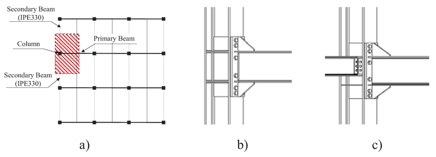
- ES1: beam IPE360 – column HE280 B;
- ES2: beam IPE450 – column HE340 B;
- ES3: beam IPE600 – column HE500 B.
All the investigated assemblies are composed by one column, one primary beam and two secondary beams. The secondary beams have the same cross section for all the investigated joints and they are designed to resist gravity loads. Moreover, in order to have all steel behaviour, any interaction between the concrete slab and the column has been avoided.
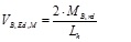
The ESEP connection is considered for the primary moment resisting plane, while a Double Cleat (DC) connection is adopted in the transverse direction. The first type of connection was ere seismically designed according to D’Aniello et al [16]. In particular, all the ESEP joints are designed as full strength, namely to ensure the formation of the plastic hinge at the beam extremity when subject to the seismic action. The capacity design requirements to obtain the required joint behaviour can be guaranteed by satisfying the following inequality:
 |
(1) |
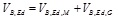
Where Mwp,Rd is the flexural resistance corresponding to the strength of column web panel; Mcon,Rd is the flexural strength of the connection; Mcon,Ed is the design bending moment at the column face; γsh accounts for strain hardening and it is assumed equal to 1.2 [16]; γov accounts for the random variability of steel yield stress and it is assumed equal to 1.25 according to EN1998-1 [22]; MB,Rd is the plastic flexural strength of the connected beam; sh is the distance between the column face and the tip of the rib stiffener; VB,Ed is the shear force corresponding to the occurring of the plastic hinge in the connected beam; it is given by:
 |
(2) |
where VB,Ed,G is the contribution due to the gravity loads that is calculated in the section where theoretically the plastic hinge is expected to form. VB,Ed,M is the shear force due to the formation of plastic hinges at both beam ends, spaced by the length Lh (the approximate distance between plastic hinges) and calculated as:
 |
(3) |
The DC connections were designed to ensure at column face the transmission of only the shear forces from the secondary beam to the column. The features of the analyszed joints are depicted in Fig. (2) and reported in Tables 1 and 2.
| Joint Assembly |
End-Plate | Rib | Bolt Position | Sup. Web Panel | ||||||||
|---|---|---|---|---|---|---|---|---|---|---|---|---|
| h | b | t | b | A | d | e | w | p1 | p2 | N° | t | |
| mm | mm | mm | mm | mm | mm | mm | mm | mm | mm | - | mm | |
| ES1-F | 760 | 260 | 25 | 200 | 235 | 30 | 50 | 150 | 75 | 160 | 2 | 8 |
| ES2-F | 870 | 280 | 25 | 210 | 250 | 30 | 50 | 150 | 75 | 180 | 2 | 10 |
| ES3-F | 1100 | 280 | 30 | 250 | 295 | 36 | 55 | 160 | 95 | 210 | 2 | 15 |
| Diameter | Double Cleat Connection | |||||||
|---|---|---|---|---|---|---|---|---|
| dBolts | dHole | hAP | bAP | tAP | lAP | e0 | e1 | e2 |
| [mm] | [mm] | [mm] | [mm] | [mm] | [mm] | [mm] | [mm] | [mm] |
| 16 | 18 | 240 | 90 | 5 | 180 | 55 | 65 | 65 |
3. FEM MODELS
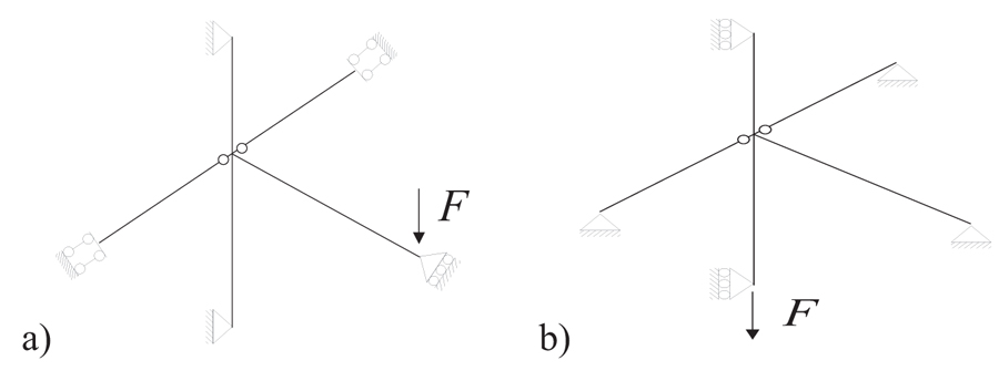
The influence of the secondary beam and its connection on the joint global behaviour was investigated by means of numerical analyses performed in Abaqus 6.14 [23]. Two Finite Element Models (FEMs) were developed as per the investigated assembly. The first model (Fig. 1b) was built dis-regarding the presence of the secondary beam, while the second model considers both the two secondary beams and their connections (Fig. 1c). Moreover, two column loss scenarios were investigated: (i) considering the loss of the column adjacent to the investigated node (CLSC1) and (ii) considering the loss of the column of the instigated node (CLSC2) (Fig. 3)
All parts (i.e. columns, beams, bolts, plates and stiffeners) were modelled using C3D8R (i.e. an 8-node linear brick, reduced integration, hourglass control) solid finite elements. Three types of interactions were implemented in FE models: (i) tie constrains, (ii) rigid body constrains and (iii) general contact interaction. The first type of constraints ties two separate surfaces together avoiding the relative displacement between them. This type of contact was introduced to represent the full penetration weld behaviour between the continuity plate and the column, the end-plate and the beam and the beam and the rib stiffeners.
The Rigid-body constraint allows simulating the planar behaviour of a cross section and integrating the global mechanic response of the whole section in one point. This type of constrains was introduced to apply the boundary condition corresponding to the whole section in just one point. The interaction between two steel surfaces in contact was modelled, introducing the contact interaction that allows accounting for the interaction between surfaces characterized by friction sliding. In particular, “Coulomb Friction” was used in order to describe the tangential behaviour with a friction coefficient equal to 0.3, while “Hard Contact” was selected to characterize the normal behaviour. The materiasl assumed for beams, column and the stiffeners were an European S355 steel with average yield stress equal to 1.25 times the yield stress fy, as recommended by EN1998-1-1 [22]. The plastic hardening was simulated using both nonlinear kinematic and isotropic hardening law [26] on the basis of a set of coupon tests performed within the EQUALJOINTs research project [15]. The pre-loadable bolts were modelled with the equivalent shank approach as proposed by [24, 25, 27].
4. RESULT
In the case of column loss scenario, the presence of the axial restrains at the beam ends (Fig. 3) induces the development of the catenary action that changes the internal actions in both the beam and the joint. The actual bending moment acting at column face under the CLSC1 and CLSC2 scenarios should be calculated accounting for the developed catenary action as follows:
 |
(4) |
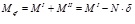
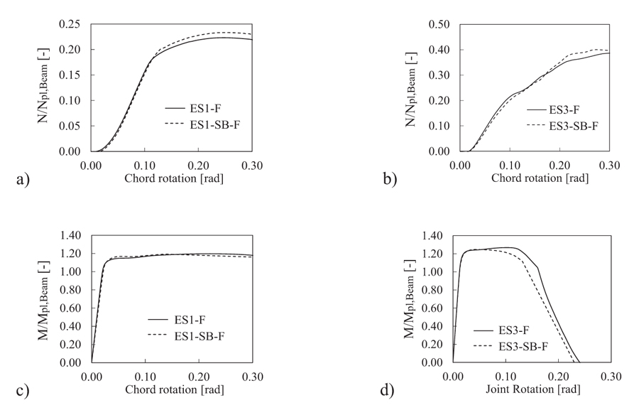
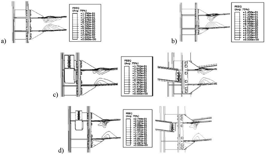
Where, is the first order moment due to the loads transversally applied to the beam (e.g., being F the transverse shear applied at the beam tip and is the corresponding vertical displacement), while is the second order moment due to the catenary action . The results of ES1 and ES3 joint assemblies are reported in terms of axial force and total moment at the column face normalized aswith respect to the plastic axial (Npl,beam) and bending (Mpl,beam) strength of the main beam, respectively (Fig. 4). The corresponding PEEQ distribution at 10% of imposed rotation are depicted in Fig. (5). The ES1 assemblies (i.e. ES1-F without secondary beams and ES1-SB-F with secondary beams) show a ductile behaviour up to 20% of the chord rotation, while some differences can be observed only in terms of the normal action distribution, consistently to the main findings by [28].
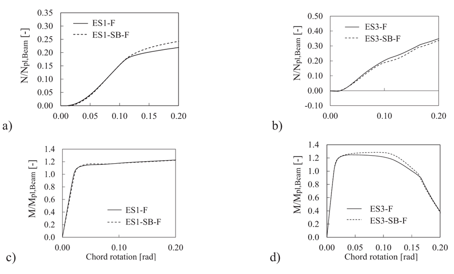
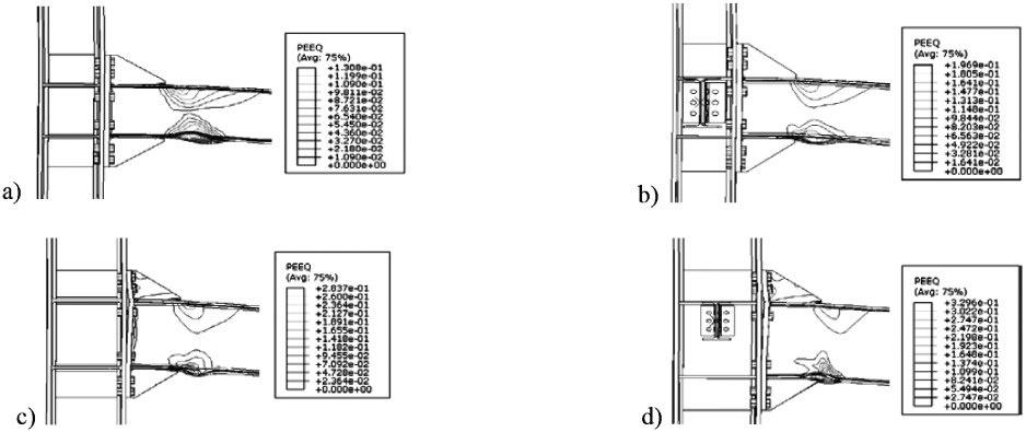
Fig. (4a) shows for the ES1-SB-F an increase of the normal action in the beam at rotation larger than 10%. This increase of the normal action is due to the larger stiffness of the connection; indeed, in this case, the connection rotation is countered by the torsional stiffness of the two secondary beams. ES3 joints show different response. Indeed, in this case, the catenary action is not affected by the presence of secondary beams, while some differences can be observed in terms of bending moments. Indeed, the ES3-F joint is less ductile showing the premature failure of the two upper bolt rows at rotation equal to 15%, while the case with the secondary beams despite exhibits the loss of bolts for larger rotation demand (Fig. 4d).
As it can be observed that the influence of the secondary beams does not affect the yielding line distribution, both the joint configurations (i.e. ES1 and ES3) show the formation of the plastic hinge at the beam extremity Fig. (6). However, it is important to notice that for both the investigated cases the maximum value of the PEEQ is are shown by the model with the secondary beam. Similar results were obtained for the second robustness scenario (CLSC2), (Fig. 5). Under this robustness scenario, the secondary beam plays a different role in the definition of the joint behaviour. Indeed, according to the boundary conditions (Fig. 3b), the secondary beams should work as truss elements under large imposed deformations.
Some differences can be pointed out both in terms of the normal action distribution (i.e. for the ES1) and in terms of joint ductility (i.e. ES3). Fig. (7) shows the torsional deformations of the secondary beams. In addition, it can be observed that the double cleat connections exhibit severe plastic deformations. This aspect it is very important because their premature failure can impair the in-tegrity of the entire floor system with the activation of a chain collapse mechanism of the slab.
CONCLUSION
In light of the results of the finite element simulations presented and discussed in the previous sections, the following remarks can be drawn:
- The presence of the secondary beams improves the joint performance under column loss thanks to their torsional stiffness; when the dimensions of the double cleat connection are comparable with those of the primary moment resisting joint (e.g. ES1-SB-F), they are also able to increase the stiffness of the entire joint.
- Severe plastic deformation can be observed in the double cleat connections in joints directly affected by the column loss (e.g. CLSC2). Therefore, these connections should be properly designed in order to guarantee adequate ductility.
CONSENT FOR PUBLICATION
Not applicable.
CONFLICT OF INTEREST
The authors declare no conflict of interest, financial or otherwise.
ACKNOWLEDGEMENTS
Declared none.

