All published articles of this journal are available on ScienceDirect.

Comparison Between Different Design Strategies For Freedam Frames: Push-Overs and Ida Analyses
Authors Info & Affiliations
Abstract
Background:
Modern seismic code design rules are known to be based on capacity design principles. They try to assure the damage to occur in the ductile parts of the structure, such as beam ends while the other have to remain in elastic range. Therefore, in the aftermath of design earthquakes, plastic deformations at member or connection level will imply high repair costs. In the last decades, innovative structural solutions based on the so-called supplementary energy dissipation strategy allow increasing the dissipative capacity of structures through equipping it with special damping devices. In the case of substitution of dissipative zones with dissipative devices the strategy takes the name of substitutive strategy. This is the case of Moment Resisting Frames investigated in this paper, where traditional dissipa-tive zones, are equipped with innovative low damage frictional devices. However, the current version of codes does not provide any rules to design of MRFs equipped with this type of friction joints.
Methods:
Therefore, this paper reports two design approaches amply investigated and compared. The first one is based on the application of the Beam-to-Column Hierarchy Criterion (BCHC) while the second one exploits the Theory of Plastic Mechanism Control (TPMC). The comparison between them is herein discussed on the basis of the results of nonlinear static and dynamic analyses.
Conclusions:
Structures equipped with low damage frictional connections show larger drift demand than conventional Moment Resisting Frames. However, differently from traditional structures, the larger displacement demand of MRFs equipped with friction joints does not corre-spond to structural damage, thus allowing the reparability of the structure.
1. INTRODUCTION
Steel Moment Resisting Frames (MRFs) designed in accordance with modern seismic design codes, e.g. Eurocode 8 [1] and the AISC 341-16 [2], need to resist seismic events by forming plastic hinges at the beam level [3-5]. In this way, a collapse mechanism of global type can be achieved also if first storey columns base sections are involved in plastic range, with the assurance of safety preservation but with the downside of high repair costs in the earthquake aftermath. In fact, dissipative zones,i.e. beam ends during a seismic event are widely involved in plastic range and are very hard to be substituted. For this reason, in last decades, research efforts were addressed to the practical development of new strategies whose goal is the design of connections able to withstand, almost without any damage, not only frequent and occasional seismic events, but also destructive earthquakes such as those corresponding to rare and very rare events. The basic idea of these new researches [6-14] is inspired by the strategy of supplementary energy dissipation, but it is based on the use of damping devices under a new perspective. While passive control strategies have been commonly based on the integration of the energy dissipation capacity of the primary structure by means of a supplementary dissipation coming from damping devices; the new design strategy is based on the use of friction dampers conceived, in such a way, to substitute the traditional dissipative zones of MRFs,i.e. the beam ends. To this scope, beam-to-column connections can be equipped with friction dampers which can be located either at the level of the two flanges [6-10] or at the bottom flange level only [15]. Also, the beam web-to-column flange connection can be equipped with friction dampers. Moreover, symmetrical or asymmetrical friction devices can be exploited [16, 18]. In this work, MRFs are equipped with innovative frictional connection called FREEDAM dampers, where the dissipative zone, constituted by a layer of frictional material is located at the bottom flange of the beam ends.
Within the ongoing RFCS FREEDAM project, friction devices able to dissipate the seismic input by means of relative sliding at the beam ends are prequalified. Using this type of device, the MRF is designed for drift considerations just like an EC8 compliant frame, while the friction connection (damper) is designed as the dissipative element (substituting the beam plastic hinge), considering the seismic combination forces [17]. In this way, the traditional MRFs become structures with sufficient stiffness, less overdesigned and low post-earthquake damage, owing to the less demanding hierarchy rule and the dissipation mechanism.
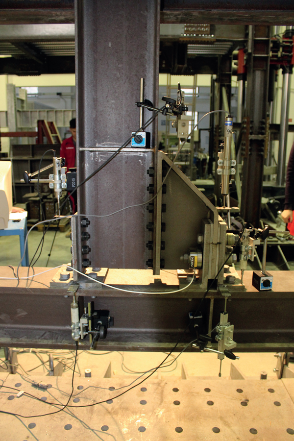
The friction connections dissipate energy by relative sliding of plates held in contact by preloaded bolts. The friction properties are given by the friction pads,i.e. special plates that undergo surface treatments, while the slipping part Fig. (1) is made out of stainless steel, due to its higher superficial hardness. The hysteretic response of this joint typologies is strictly related with the material of the friction pads, but typically they exhibit stable cyclic behaviour with minimal resistance, stiffness and ductility degradation [19-20]. Therefore, the damage in the structural elements is highly mitigated and localized in easily substitutable parts, at the friction connection level, meaning that frames equipped with friction joints could be called free from damage moment resisting frames (FD-MRFs).
The design of FD-MRFs can be assumed to be similar to one of the traditional MRFs, although, the former frames have particularities that require attention. In particular, starting from EC8 compliant frames [21], the dissipation mechanism is different (the plastic deformation is replaced by relative sliding). Therefore, the overstrength coefficient to be taken into consideration for the design of non-dissipative elements needs to be evaluated differently.
Indeed, the material overstrength factor γov is no longer relevant, as well as the material uncertainty coefficient 1,1. Furthermore, the design overstrength, in the way it is typically defined (the ratio between the beam flexural strength MRd and the design bending moment MEd) is no longer valid due to the change of the dissipative mechanism.
The work hereby presented focuses on two procedures for the design of FD-MRFs: the first one is compliant with the design rules based on the so-called beam-column hierarchy criterion, while the second one exploits the Theory of Plastic Mechanism Control (TPMC). The two methodologies are denominated as follows: (i) FD-BCHC where the structure is designed according to beam-column hierarchy criterion; (ii) FD-TPMC where the structures are designed according to TPMC. In particular, two sets of frames were designed and analysed considering the proposed methodologies: the first one with full strength connections and the second one with FREEDAM connections. Finally, the response of the designed structures is investigated by means of push-over and IDA analyses, and differences between both the design approaches are pointed out.
2. DESIGN PROCEDURES
2.1. EC8 compliant design methodology
The MRFs equipped with friction devices can be designed following the recommendations of Eurocode 8, with minor alterations to the capacity design procedure. The hereby proposed procedure uses the same algorithm for the initial design of the structurei.e. once the geometrical configuration is established and the forces are applied (considering the EC1 recommendations) the SLS limitations are verified. This will be the condition that primarily dictates the beam and column member profiles. The following step consists in the design of the dissipative element (the friction connection) for the design forces coming from the seismic combination. In particular, the slip force (Fslip) is calibrated for a level of moment compatible with the bending moment at the end of the beam from the seismic combination (MEd). Equation 1 depicts the way to determine the design force for the friction connection, considering the notations previously described and assuming z as the lever arm between the compression and tension forces.
 |
(1) |
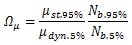
Subsequently, the non-dissipative elements (beams, columns, connections) are designed considering an overstrength with respect to the dissipative element. The overstrength factor Ω is essential for this step, but it is evaluated based on different considerations compared with the typical plastic mechanism. Indeed, the yield strength variability, the hardening of the steel or the beam overdesign are no longer relevant for the capacity design. Instead, the variability in terms of dynamic and static friction coefficient (μ) and the clamping force applied at the damper level, are both determinants for the sliding phenomena, contribute to the definition of Ωµ (Eq. (2)).
 |
(2) |
where:
- µdyn.5%, Nb.5.% lower-bound values of dynamic friction coefficient and tightening force
- µdst.5%, Nb.95.% upper-bound values of static friction coefficient and tightening force
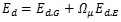
The design forces for the non-dissipative elements are evaluated based on Eq. (3).
 |
(3) |
where Ed is the design value of the internal forces for non-dissipative elements, Ed.G is the effect coming from gravitational loads and Ed.E is the effect coming from the seismic action.
The resistance and stability checks for the members (beams and columns) and the design of connections, must be done according to EN 1993 1-1 and 1-8, respectively. In the end, the local hierarchy at the node must be checked, again, as recommended by EC8.
2.2. TPMC Compliant Design Methodology
TPMC is based on a rigorous theoretical approach assuring a collapse mechanism of global type [22], which exploits the kinematic theorem of plastic collapse extended to the concept of mechanism equilibrium curve:
 |
(4) |
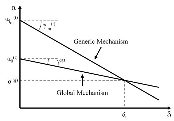
where, following the theory of rigid-plastic analysis, α 0 is the first order collapse multiplier of horizontal forces, γ is the slope of the linearized mechanism equilibrium curve due to second order effects and δ is the plastic top sway displacement. TPMC states that the mechanism equilibrium curve corresponding to the global mechanism has to be located below those corresponding to all the undesired mechanisms until a design displacement δu compatible with the local ductility supply [22], Fig. (2). The column sections at each storey that guarantee a global collapse mechanism are the unknowns of the design problem, while the dissipative zones are preliminarily designed according to the first principle of capacity design. More details about this design procedure applied can be found in [22-28] for steel MRFs and MRFs equipped with friction dampers.
3. ANALYZED SCHEMES
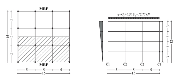
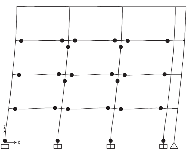
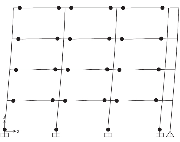
In order to assess the performance of MRFs equipped with friction devices, 2 frames alternatively designed according to both design approaches have been analyzed, namely: (i) MRFs with full strength connections and (ii) MRFs with FREEDAM dampers. The study cases herein investigated refers to a building whose plan configuration is depicted in Fig. (3). The structure is a 4 storey perimetral frame with 3 spans of 5m in both directions. In particular, MRFs are located in the longitudinal direction (x), while concentrically braced frames are considered in the transverse direction (y). Fig. (3) shows also the leaning column adopted in structural modelling to account for second order effects due to the internal gravity load resisting system. In addition, permanent Gk and live Qk loads considered for the structural analysis and evaluation of masses corresponding to the gravitational frames, chosen within a practical range, are reported in (Table 1).
| Location | Type | Load [kN/m2] | ψ2,i | ψE,i |
|---|---|---|---|---|
| Roof | Permanent | 4.5 | 0.3 | 0.24 |
| Variable | 2 | |||
| Intermediate Stories | Permanent | 4.5 | 0.3 | 0.15 |
| Variable | 2 |
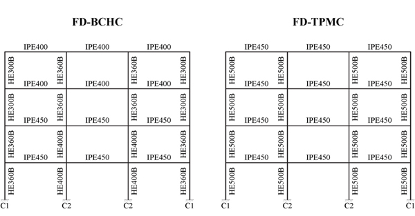
S275 steel grade (fyk = 275 MPa) was used for all members of the frames. The beams of the MRF were designed to withstand vertical loads accounting also for serviceability requirements. The design horizontal forces were determined according to EC8, assuming a peak ground acceleration equal to 0.35g, a seismic response factor equal to 2.5, a behaviour factor equal to 6.5 for the design spectrum with a 2% damping, a response spectrum Type 1 and soil Type C. The effects of second order (P-Δ) effects are accounted for in the design as well as the accidental torsional effects. The interstorey drift for serviceability conditions was limited to 1.0% of the storey height. Global and local ductility requirements according to EN 1998-1 [1] were checked. Fig. (4) reports the shapes of the members of the designed frames.
4. PUSHOVER ANALYSES
Non-linear static analyses (push-over) were carried out by means of SAP 2000 [29]. The primary aim of this analysis is the assessment of the collapse mechanism typology and a first preliminary comparison between the performances of the structures designed with the examined design approaches.
Beams and columns were modelled by means of beam-column elements, whose non-linearities are concentrated in plastic hinges (“P-hinge” elements) located at their ends. In particular, plastic hinges accounting for the interaction between axial force and bending moment were defined for columns, while the rotational behaviour resulting from the friction dampers located at the bottom flange level of the beam ends was modelled in pure rigid-plastic bending. Therefore, the plastic moment of the corresponding “P-hinge” element is equal to the product between the slippage resistance of the friction dampers and the lever arm. All plastic elements were modelled with a rigid-plastic curve whose plastic threshold, corresponding to the slippage resistance of friction dampers, accounts for the over-strength due to the random variability of the friction coefficient and the uncertainties of the bolt preloading level. The elastic component of the structural behaviour is directly taken into account by the elasticity of the beam-column element.
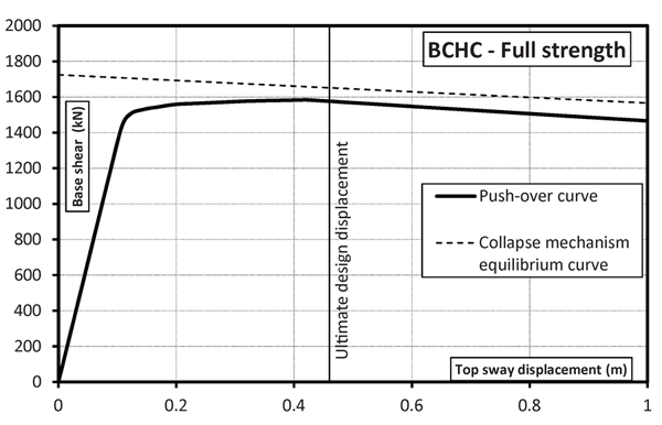
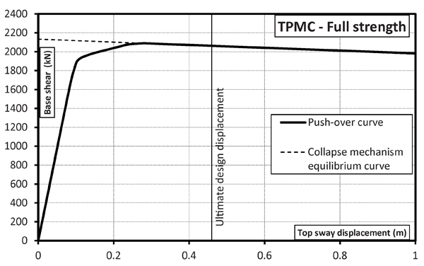
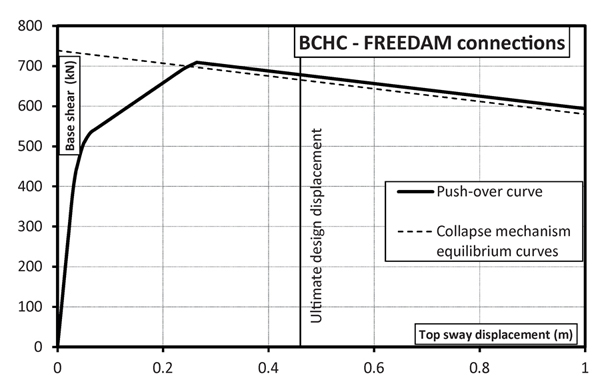
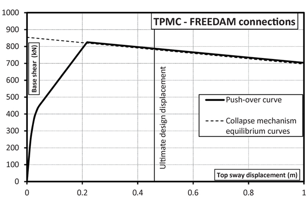
In Figs. (5-8), the validation of the nonlinear static analysis is reported with reference to MRFs with full strength connections and MRFs equipped at beam-to-column level with FREEDAM connections designed with both the proposed design approaches. The analysis was carried out under displacement control taking into account both geometrical and mechanical non-linearities. In addition, out-of-plane stability checks of compressed members were performed at each step of the non-linear analysis.
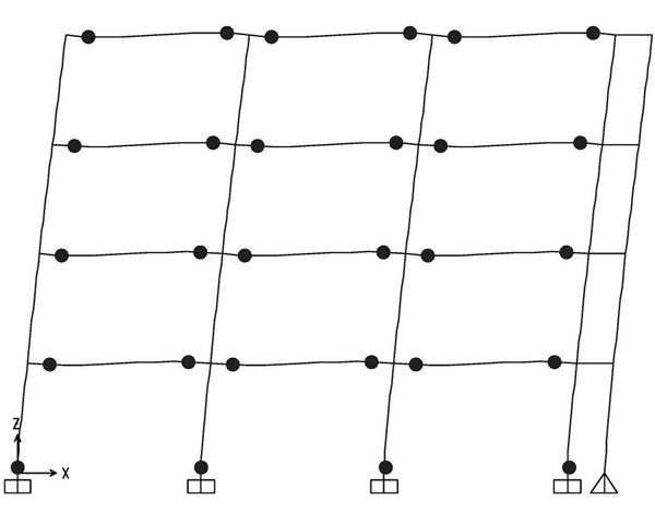
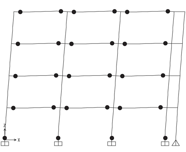
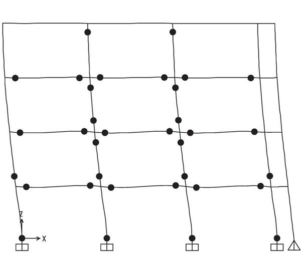
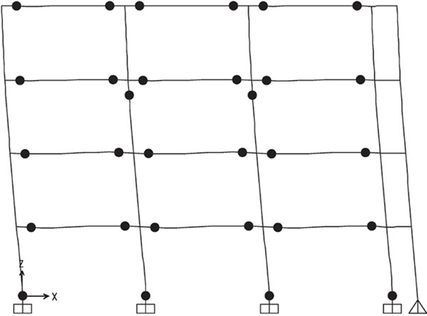
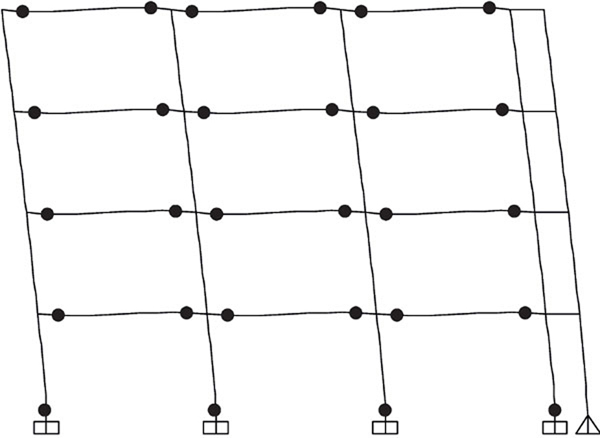
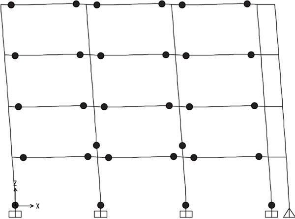
The hinge pattern of push-over curves is reported in Figs. (9-12), where it can be recognized that the structures designed by TPMC show the formation of a global mechanism at a roof displacement equal to 0.48 m. The same happens for the structure designed by beam-column hierarchy criterion but equipped with FREEDAM dampers. Conversely, the structure with full strength connections shows a partial collapse mechanism. This is also testified by the collapse mechanism equilibrium curves of Fig. (5-8) where only in Figs. (6-8) the softening branch of push-over curve perfectly coincides with the aforementioned curve. Finally, it was also checked that friction dampers do not slip under the action of the bending moment corresponding to the vertical load combination at the ultimate limit state, i.e. 1.3Gk + 1.5 Qk.
5. INCREMENTAL DYNAMIC ANALYSES
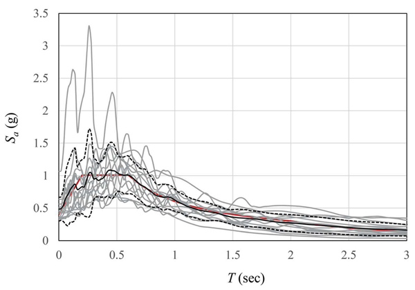
In order to provide a more robust evaluation of seismic performance of investigated structures, Incremental Dynamic Analyses (IDA) were performed. The leaning column has been modelled in order to take into account the vertical loads acting on the frame (including masses) and also the second order effects. In addition, 14 natural records were selected from RESORCE database [30] and properly scaled to match the design spectrum for the given seismicity level as reported in [26-29].The basic data of the selected ground motions are reported in (Table 3).
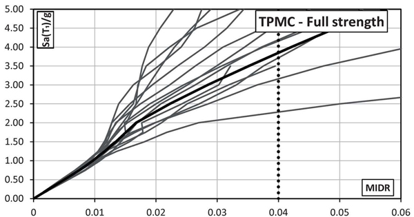
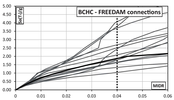
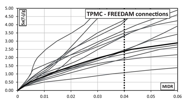
The IDA analyses were carried out by increasing the Sa(T1)/g value until the achievement of a target drift equal to 0.04 rad corresponding to the final stroke of the designed FREEDAM dampers. However, it is important to point out that this limit state does not correspond to the structural collapse because the structures owns additional dissipative capacity due to the shear mechanisms in bolts.
In addition, Rayleigh formulation for a 2% damping has been assumed with the proportional factors computed with reference to the first and second mode of vibration. The first and second period of vibration T1 and T2 are reported, for each structural scheme, in (Table 2).
|
T1 [s] |
T2 [s] |
|
|---|---|---|
| FD-BCHC | 0.65 | 0.21 |
| FD-TPMC | 0.54 | 0.16 |
| Earthquake Name | Station Name | Country | Date | Magnitude Mw | PGA [m/s2] | Length [s] |
|---|---|---|---|---|---|---|
| Alkion | Xylokastro-O.T.E. | Greece | 24.02.1981 | 6.6 | 6.69 | 17.49 |
| Montenegro | Bar-Skupstina Opstine | Montenegro | 24.05.1979 | 6.2 | 6.95 | 41.87 |
| Izmit | Yarimca (Eri) | Turkey | 13.09.1999 | 5.8 | 4.46 | 40.03 |
| Izmit | Usgs Golden Station Kor | Turkey | 13.09.1999 | 5.8 | 7.07 | 55.31 |
| Faial | Horta | Portugal | 09.07.1998 | 6.1 | 9.58 | 105.30 |
| L'Aquila | L'Aquila - V. Aterno - Aquila Park In | Italy | 06.04.2009 | 6.3 | 3.36 | 114.39 |
| Aigion | Aigio-OTE | Greece | 15.06.1995 | 6.5 | 3.22 | 124.01 |
| Alkion | Korinthos-OTE Building | Greece | 24.02.1981 | 6.6 | 4.47 | 40.01 |
| Umbria-Marche | Castelnuovo-Assisi | Italy | 26.09.1997 | 6.0 | 7.46 | 30.02 |
| Izmit | Heybeliada-Senatoryum | Turkey | 17.08.1999 | 7.4 | 5.29 | 47.34 |
| Izmit | Istanbul-Zeytinburnu | Turkey | 17.08.1999 | 7.4 | 7.46 | 48.20 |
| Ishakli | Afyon-Bayindirlik ve Iskan | Turkey | 03.02.2002 | 5.8 | 6.05 | 9.34 |
| Olfus | Ljosafoss-Hydroelectric Power | Iceland | 29.05.2008 | 6.3 | 5.63 | 93.13 |
| Olfus | Selfoss-City Hall | Iceland | 29.05.2008 | 6.3 | 6.26 | 40.03 |
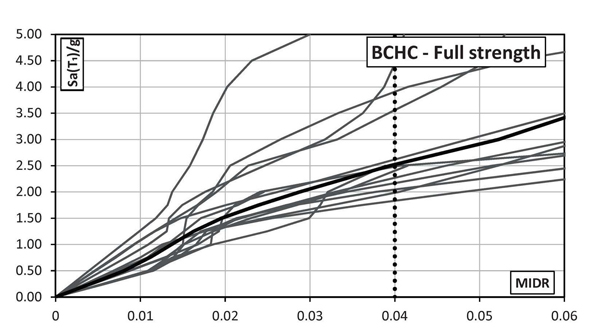
In Figs. (14-17) the MIDR curves for both full strength and FREEDAM connections designed according to both BCHC and TPMC are reported. From these figures, it is observed that at the same seismic intensity both structures with conventional MRF joints are characterized by lower displacement demand than the corresponding structures equipped with FREEDAM devices. However, in these latter cases, the larger deformation demand does not correspond to any structural damage, thus allowing easy reparability after the earthquake that is not possible in the case of conventional MRF. The comparison between BCHC and TPMC frames confirms that EC8-compliant structures do not exhibit a global mechanism.
From Figs. (18-21) hinge patterns of the analyzed schemes are depicted. Plastic hinge patterns correspond to a MIDR value equal to 0.04. In particular, the performance of the MRFs with conventional full strength joints is highly influenced by the design approach, namely for the given target MIDR, BCHC structure shows a partial collapse mechanism while that designed according to TPMC shows a full global mechanism. Conversely, both structures equipped with FREEDAM joints show the global mechanism. This finding confirms the effectiveness of using FREEDAM joints.
CONCLUSION
Two different design approaches for MRFs with or without FREEDAM connections are described and compared in this paper. The first approach is based on the application of the Beam-to-Column Hierarchy Criterion (BCHC), while the second one exploits the Theory of Plastic Mechanism Control (TPMC). A comparison between both the design approaches and the results of the new rules are herein examined by means of nonlinear static and dynamic analyses. Both designs approach applied to structures equipped with FREEDAM devices guarantee satisfactory seismic performance with damage distribution in agreement with the expected global mechanism. Conversely, the structure with full strength connections designed according to beam-column hierarchy criterion exhibits a partial collapse mechanism, while the frame designed according to TPMC is characterized by overall ductile and dissipative failure mode. Results of IDA analyses point out that, at the same seismic intensity level, FREEDAM structures show larger drift demand than conventional MRFs [31-34]. However, differently, from this latter case, the larger displacement demand of MRFs equipped with FREEDAM joints does not correspond to structural damage, thus allowing the reparability of the structure after a seismic event.
CONSENT FOR PUBLICATION
Not applicable.
CONFLICT OF INTEREST
The authors declare no conflict of interest, financial or otherwise.
ACKNOWLEDGEMENTS
The research activity herein presented has been supported by the European Community by research grant RFSR-CT-2015-00022. The support of the European Commission on RFCS Research & Innovation is gratefully acknowledged.

