All published articles of this journal are available on ScienceDirect.

Implications of Structural Model on the Design of Steel Moment Resisting Frames
Abstract
Background:
Studies have shown that the flexibility of the connections has an important role in the distribution of forces and moments in the structure. This also applies for the displacements, deformations and the stability of the structure.
Objective:
The objective of the present study is to investigate the influence of the stiffness of column web-panel and connection on the ultimate response of Moment Resisting Frames (MRFs).
Methods:
A comprehensive parametric study was carried out. In particular, a set of one hundred and twenty planar frames was analyzed, considering three approaches for modelling the joints.
Results:
The results highlight that neglecting the influence of the connection and column web panel leads to significant over-estimation of the global instability factor αcr, which can lead to unconservative design and assessment of steel frames, especially for those cases subjected to severe horizontal forces as the seismic actions.
Conclusion:
Accounting for the joint deformability in MRFs is important even for the cases with connection stiffness (kb) larger than 25 times the beam stiffness where EN1993-1-8 allows neglecting the model of the connection stiffness. Indeed, the comparison of cases with kb ≥ 25 between the models with and without the connection deformability show that of αcr can decrease from 5% to 16%, depending on the refinement of the modelling assumptions. This decrease also lead to higher second order effects and thus to higher design forces but also the overall stiffness of the frame is overestimated.
1. INTRODUCTION
The flexibility of the connections has an important role in the distribution of forces and moments in the structure. This also applies for the displacements, deformations and the stability of the structure. In order to determine if the connection flexibility needs to be included in the overall frame analysis, it is important to examine its effect on the frame behaviour.
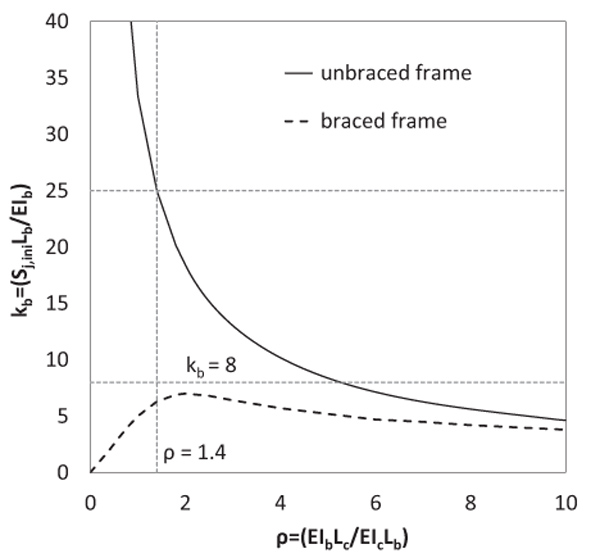
One of the early studies on this subject was undertaken by Zoetemeijer [1], which showed that elastic critical load of a single storey unbraced frame with a relative joint-to-beam stiffness kb = 25 is reduced by less than 10% as respect to its value for kb = ∞ in case of common column and beam proportions (beam-to-column stiffness ratio in the range from 10 to 0.5). It was implied that stiffness of the connection does not need to be considered in global structural analysis when kb > 25. Afterwards, Bijlaard and Steenhuis [2] demonstrated that for single storey braced and unbraced frames, who demonstrated that for a relative beam-to-column stiffness ρ equal with 1.4 and a relative joint-to-beam stiffness equal with 25 only a 5% reduction in the elastic critical load appears (Fig. 1). Using the Merchant-Rankine formula, this corresponds to a drop of not more than 5% in the load-bearing capacity. Even for a relative beam-to column stiffness smaller than 1.4 the drop in load-bearing capacity is up to 8% (corresponding to 15% drop in elastic critical load and assuming the latter is two times larger than the plastic frame resistance) [2]. Hence, it was concluded that if the joint initial stiffness (Sj,ini) is 25 times larger than the beam stiffness (EIb/Lb) it is possible to ignore the stiffness of the joint in the model. The point to be noted is that, this study was made primarily for portal frames and extended in a simplified manner on multi-storey frames. This outcome has been incorporated in the current version of EN1993-1-8 [3].
In the light of these observations, the main objective of this paper is to present the results of a large parametric investigation on the influence of joint stiffness (in particular, the column web panel and the connection) and modelling strategies on the overall structural response. Three different modelling assumptions were adopted for the joints. Also five different levels for the stiffness of the connection were considered. These sets of models and stiffness levels were applied on frames designed according to EN1993-1-1 (hereinafter also referred as EC3 or Eurocode 3) [2].
2. MODELLING ASSUMPTIONS
As previously mentioned, the investigated frames were analysed considering three different modelling assumptions for the beam-to-column joint. Fig. (2) schematically shows the three types of adopted models.
Model I: It is the most simplistic way of modeling the connection between the beam and the column, which makes it also the most commonly used option. In this model, the geometrical dimensions of the elements are not accounted for and it gives overestimated values of the internal forces because the length of the finite element is higher than the length of the real beam. This model introduces at the end of the beam element a spring that accounts for the stiffness of the connection.
Model II: This model mimics the joint region between the beam and the column, differently from model I. In particular, the function of the height of the beam/column of this model uses a rigid link at the ends of the elements, thus increasing the lateral stiffness of the system. This model also introduces at the end of the beam element a spring that accounts for the stiffness of the connection, disregarding however, the stiffness of the column web panel.
Model III: This model is also known as the Krawinkler model [4, 5]. The model consists of four rigid links connected at the corners by rotational springs. The springs at the lower left, right and upper left corners have no stiffness, and thereby act as nominal hinges. The spring at the upper right corner is used to represent the column web panel shear behaviour. In addition, a spring that accounts for the stiffness of the connection is introduced at the end of the beam. This model is the most complex and complete, accounting both for the stiffness of the connection and that of the column web panel.

From the comparison between model I and III it can be argued that the potential benefits of separate modelling of the column web panel and the connection, are the following:
- No need to analyse separate structural models for each load combination;
- No iterative process of structural design due to the need to re-calculate joint properties for changing distribution of beam moments at interior joints;
- Straightforward calculation of the design shear force in the column web panel by reducing it due to the shear force in columns framing into the joint, thus lead to more economical design compared to results obtained according to application rules in EN1993-1-8 [3];
- Correct modelling of varying moment distribution on the column web panel in case of global plastic analysis with non-proportional loading;
- The beam-to-column model is consistent with requirements of the global plastic analysis according to EN1993-1-1 [6] and the joint design to EN 1993-1-8 [3].
However, the use of refined models that separate the connection and column web panel needs the revision of the boundary limits kb for rigid connections. Therefore, kb was systematically varied in the parametric study described in this paper.
Table 1 summarizes all the models that were investigated. For each of the three modelling approaches, five different values of connection stiffness were assumed, expressed as the ratio between connection and beam stiffness (kb = ∞, 50, 25, 12.5, 6.25). As it is trivial to recognize, a set of fifteen models were obtained in function of the joint modelling strategy and the levels of the connection stiffness.
| kb | Model I | Model II | Model III |
|---|---|---|---|
| ∞ | M1 | M2 | M3 |
| 50 | M1-50 | M2-50 | M3-50 |
| 25 | M1-25 | M2-25 | M3-25 |
| 12.5 | M1-12.5 | M2-12.5 | M3-12.5 |
| 6.25 | M1-6.25 | M2-6.25 | M3-6.25 |
3. PARAMETRIC STUDY
The geometrical configuration of the structure considered for the parametric study is presented in Fig. (3). For the design phase, only the frame from alignment “4” was considered.
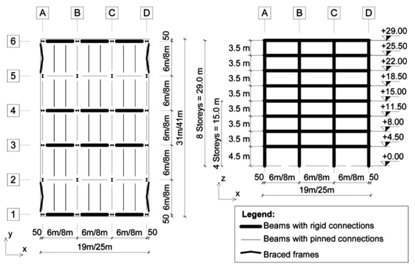
Four structural configurations were examined. The frames were extracted from buildings obtained by varying the number of storeys (4 and 8) and the bay length (6 and 8 meters). The frames were designed to resist gravity loads and wind forces. The seismic forces were intentionally kept out of this study. The snow and wind loads were estimated for two locations in Romania, namely Bucharest and Timisoara. Finally, a set of 8 frames was obtained. Table 2 depicts the names and the main characteristics of the frames.
| Name | Location | Number of Storeys | Bay Length [m] |
|---|---|---|---|
| MB46 | Bucharest | 4 | 6.0 |
| MB48 | Bucharest | 4 | 8.0 |
| MB86 | Bucharest | 8 | 6.0 |
| MB88 | Bucharest | 8 | 8.0 |
| MT46 | Timisoara | 4 | 6.0 |
| MT48 | Timisoara | 4 | 8.0 |
| MT86 | Timisoara | 8 | 6.0 |
| MT88 | Timisoara | 8 | 8.0 |
The characteristic values of the design loads are the following: permanent load equal to 5 kN/m2; live load equal to 3 kN/m2; snow load equal to 1.2 kN/m2 and 1.6 kN/m2 for Timisoara and Bucharest, respectively; wind load for Timisoara 0.6 kN/m2 and for Bucharest: 0.5 kN/m2. The permanent load accounts for the weight of the slab, pavement finishes, HVAC systems and the ceiling. The live load has been taken according to EN1991-1 [7] for category B (office areas). The wind and snow actions were defined according to the Romanian codes CR-1-1-4 and CR-1-1-3, which are similar to the EN1991-1-4 [8] and EN1991-1-3 [9], respectively. The global initial sway imperfections were computed according to EN1993-1-1 [6] and these effects were modelled by means of equivalent horizontal forces.
The design of the frames was made according to EN1993-1-1 [6]. The design criteria that were considered are: resistance, stability, top displacement at SLS = H/500 = 0.20%, interstorey drift at SLS = H/400 = 0.25%, beam deflection at SLS = L/250 and αcr ≥ 3.
Taking all these into account, the member sections obtained from the design are given in Table 3.
| st | MB46 | MT46 | MB48 | MT48 | MB86 | MT86 | MB88 | MT88 | |
|---|---|---|---|---|---|---|---|---|---|
| Beams | 8 | - | - | - | - | IPE330 | IPE330 | IPE450 | IPE450 |
| 7 | - | - | - | - | IPE360 | IPE360 | IPE450 | IPE500 | |
| 6 | - | - | - | - | IPE400 | IPE400 | IPE500 | IPE500 | |
| 5 | - | - | - | - | IPE400 | IPE500 | IPE550 | IPE600 | |
| 4 | IPE330 | IPE330 | IPE450 | IPE450 | IPE450 | IPE500 | IPE550 | IPE600 | |
| 3 | IPE330 | IPE330 | IPE450 | IPE450 | IPE500 | IPE500 | IPE600 | IPE600 | |
| 2 | IPE360 | IPE400 | IPE500 | IPE500 | IPE500 | IPE550 | IPE750 | IPE750 | |
| 1 | IPE400 | IPE450 | IPE500 | IPE500 | IPE500 | IPE550 | IPE600 | IPE750 | |
| Columns | 8 | - | - | - | - | HEB280 | HEB280 | HEB300 | HEB300 |
| 7 | - | - | - | - | HEB280 | HEB280 | HEB300 | HEB300 | |
| 6 | - | - | - | - | HEB360 | HEB360 | HEM300 | HEM300 | |
| 5 | - | - | - | - | HEB360 | HEB360 | HEM300 | HEM300 | |
| 4 | HEB260 | HEB260 | HEB300 | HEB300 | HEB360 | HEB360 | HEM300 | HEM300 | |
| 3 | HEB260 | HEB260 | HEB300 | HEB300 | HEB450 | HEB450 | HEM340 | HEM340 | |
| 2 | HEB280 | HEB280 | HEB340 | HEB340 | HEB450 | HEB450 | HEM340 | HEM340 | |
| 1 | HEB280 | HEB280 | HEB340 | HEB340 | HEB450 | HEB450 | HEM340 | HEM340 |
It is important to mention that serviceability criteria (interstorey drifts and top displacements) governed the design of most frames. Only the MB48 and MT48 frames were designed from a resistance point of view.
4. NUMERICAL ANALYSIS
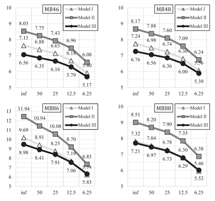
The main parameter considered for the evaluation of the frame performance is αcr (the global instability factor). The values obtained for the frames designed in Bucharest are presented in Fig. (4). In almost all cases, the second order-effects cannot be neglected (αcr < 10). This is true also for the frames designed in Timisoara. It is important to mention that for the frames designed in Timisoara a similar pattern is obtained in the decrease of αcr but the values are slightly higher in comparison with the Bucharest cases.
From Fig. (4) it can be observed that the tendency of αcr is to decrease with smaller the stiffness of the connection. This observation is true for all three sets of frames (function of the joint modelling strategy). This implies that the second order effects are more important with the decrease of the stiffness of the connection.
| kb | 50 | 25 | 12.5 | 6.25 |
|---|---|---|---|---|
| Model I | 2% - 8% | 5% - 15% | 10% - 26% | 19% - 41% |
| Model II | 2% - 8% | 5% - 16% | 9% - 27% | 19% - 43% |
| Model III | 2% - 6% | 5% - 12% | 9% - 21% | 18% - 35% |
It is interesting to compare the results considering the three joint models and the connection stiffness variation. Table 4 depicts the variation of the stability parameter αcr for frames with non-dimensional connection stiffness ranging from 50 to 6.25 with respect to the model with infinitely rigid connections. Indeed, it is possible to observe differences in terms of αcr that range between 2% and 43%.
For a stiffness of the connection 25 times larger than that of the beam (i.e. the limit for rigid joints according to EN 1993-1-8 [3]), the differences are between 5% and 16%. It can be observed that for multi-storey buildings the 5% limit for drop in elastic critical load adopted in [2] does not apply. Going from a single storey to a multi-storey frame, the maximum difference for single storey becomes the minimum difference in multi-storey. A maximum 5% drop in the Euler buckling force for single storey frame becomes a minimum 5% drop in the force for multi-storey frames and can go up to 16%. Nevertheless, this corresponds to a drop to only 4.6% in the load-bearing capacity of the frames using Merchant-Rankine formula, assuming the elastic critical load is three times the plastic frame resistance). Considering that αcr ≥ 3 for all frames considered in this study, this assumption is a valid one.
Moreover, it is important to assess the efficiency of the three models adopted for the joint. To this regard, Fig. (5) depicts the αcr values normalized with respect to the values for model III for the case with infinite stiffness of the connection. Also in Table 5 are presented all the differences taking into account all the levels for the connection stiffness.
It is important to relate model I and model II to model III because the latter is the most realistic (it takes into account explicitly the stiffness of the column web panel). Therefore, it can be highlighted that going from model III to model II an increase in stiffness is obtained because of the rigid elements at the end of the beams and columns. These rigid ends increase the stiffness of the frame, thus leading to larger values of αcr. The increase varies from 16% to 34 and it is also evident for all analysed levels of connection stiffness.
| MB46 | MB48 | MB86 | MB88 | MT46 | MT48 | MT86 | MT88 | |
|---|---|---|---|---|---|---|---|---|
| Model I | 4-9% | 3-7% | 0-8% | 0-1% | 6-8% | 3-7% | 0-9% | 0-3% |
| Model II | 18-22% | 16-21% | 18-33% | 16-18% | 20-21% | 16-21% | 20-34% | 18-20% |
On the other hand, comparing model I to model III (i.e. the least and the most detailed) an increase in stiffness is observed. These results are consistent, due to the fact that when the stiffness of the column web panel is modelled, the overall stiffness of the frame decreases. Nevertheless, the increase of αcr is up to 9%, with the mention that, in some cases, there is no increase. It can also be seen that for structures that are taller (e.g. 8 storeys), and have longer spans (e.g. 8 m), model I and III are similar. This can be seen in Fig. (4) for MB88 case. Here the model I curve overlaps over the model III curve. The differences between model III and model I in terms of αcr, are up to 3% for the cases with 8 storeys and span length equal to 8 m. The largest increase in αcr of model I (centreline model neglecting flexibility of the column web panel) with respect to model III (explicitly modelling for column web panel) is 9%. This corresponds to an overestimation of only 2.4% in the load-bearing capacity of the frames using Merchant-Rankine formula, assuming the elastic critical load is three times the plastic frame resistance). Therefore, it can be concluded that column web panel flexibility can be neglected in global structural analysis provided the centreline model (M1) is adopted. On the other hand, adopting rigid end offsets (M2) corresponds to a maximum increase in αcr of 34% with respect to the refined model (M3), and a corresponding overestimation of 11.4% of load-bearing capacity, which might be considered unacceptable.
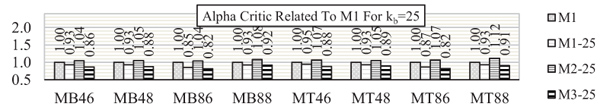
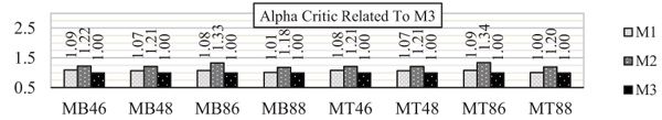
Taking as reference the frame considering the most used and simplest joint modelling scheme (i.e. M1 – the model with adjoining members connected directly and infinite stiffness of the connection), it is interesting to observe in Fig. (6) the variation of the structure’s stability when considering the connection stiffness kb equal to 25, namely the rigid limit of EC3-1-8 [3]. Under this assumption, a decrease of up to 15% of αcr can be observed when comparing M1 (the model that current EN1993-1-8 [3] recommends if the connection is 25 times stiffer than the connected beam) with M1-25 (the same model but with a spring at the end of the beam element that takes into account the stiffness of the connection which in this case is kb = 25). As for the most detailed model (i.e. M3-25 - the model with both the stiffness of the connection and the stiffness of the column web panel), a larger reduction that goes up to 18% can be noted. It can be also recognized that the column web panel induces an additional decrease ranging from 3% to 6%.
Finally, comparing M1 with M2-25 (i.e. the model accounting for the connection stiffness by means of flexural springs and the column web panel by means of rigid links), an increase of 12% is obtained.
These results highlight the fact that neglecting the influence of the connection and column web panel (by assuming them infinitely rigid) leads to significant over-estimation of αcr, which can lead to unconservative design and assessment of steel frames, especially for those cases subjected to severe horizontal forces as the seismic actions. Several studies highlighted that the seismic design of MRFs according to Eurocodes is highly influenced by stability verifications.
CONCLUDING REMARKS
The response of the multi-storey moment resisting frames is influenced by the elastic and non-linear behaviour of their joints.
In this paper, the influence of the elastic stiffness of both the connection and the column web panel was investigated separately. With this regard, three different modelling assumptions for the beam-to-column joint were examined. For every modelling approach of the beam-to-column joint, the tendency of αcr is to decrease with the stiffness of the connection.
Accounting for the joint deformability in MRFs is important even for the cases with connection stiffness (kb) larger than 25 times the beam stiffness where EN1993-1-8 [3] allows neglecting the model of the connection stiffness. Indeed, the comparison of cases with kb ≥ 25 between the models with and without the connection deformability show that of αcr can decrease from 5% to 16%, depending on the refinement of the modelling assumptions. This decrease also lead to higher second order effects and thus to higher design forces but also the overall stiffness of the frame is overestimated. While load-bearing capacity of frames obtained using Merchant-Rankine formula decreases by less than 5% in these conditions (and assuming elastic critical load is three times larger than the plastic frame resistance), the serviceability criteria (limitation of deformations) may fail to be fulfilled.
Also, it is important to underline that, from a design point of view, even for a stiffness 25 times larger the beam stiffness, the frames (excluding here the frames that were designed from a resistance point of view: MB48 and MT48) need to be redesigned if either model I (M1-25) or model III (M3-25) are used. This happens because M1 (the model that Eurocode allows using if the normalized connection stiffness kb is larger than 25) overestimates the overall stiffness of the multi-storey frame by up to 18% if a more advanced model is used.
The column web panel flexibility can be generally neglected in global structural analysis provided the centreline model (M1) is adopted, as it leads to overestimation of the elastic critical force by up to 9%, but only 2.4% overestimation of load-bearing resistance. On the other hand, adopting rigid end offsets (M2) corresponds to a maximum increase in αcr of 34% with respect to the refined model (M3), and a corresponding overestimation by 11.4% of load-bearing capacity, which might be considered unacceptable.
Of course, the model that is used in calculation needs to represent the reality. This means that if the column web panel is stiffened, model II can be used to obtain an increase in the overall frame stiffness.
Finally, based on the numerical results described in this study, if model III is used (i.e. the column web panel and the connection are modelled separately) a value of kb = 50 for the connection provides the same level of accuracy in obtaining design forces and moments as the current application rules in EN 1993-1-8[3].
CONSENT FOR PUBLICATION
Not applicable.
CONFLICT OF INTEREST
The authors declare no conflict of interest, financial or otherwise.
ACKNOWLEDGEMENTS
Declared none.

