All published articles of this journal are available on ScienceDirect.

Equivalent Load Method in Calculating Thermal Stresses during the Construction of Massive Monolithic Concrete Structures
Abstract
Introduction
Construction of massive monolithic structures requires assessing the risk of early cracking at the stage of concrete hardening. Most finite element method (FEM) programs do not allow taking into account the change in the mechanical properties of concrete over time in thermal stresses calculation for hardening monolithic structures. The purpose of this article is to eliminate this shortcoming.
Materials and Methods
A new method is proposed that allows the use of standard finite element software in the task of calculating thermal stresses in hardening concrete without any modifications. It was shown that, instead of a structure with a time-varying modulus of elasticity, it is possible to calculate a structure with a constant modulus of elasticity by replacing the actual temperature load with an equivalent one.
Results
The developed method was tested using the example of the foundation slab. The discrepancy between the calculation results according to our method and the results for a time-varying modulus of elasticity of concrete is insignificant. There is also a satisfactory agreement (discrepancy is less than 5%) with the experimental data up to 6 days, when the risk of early crack formation is highest.
Discussion
A number of works suggest expressing temperature stresses through the temperature difference between the center and the surface of the structure. It was shown that instead of the actual temperature difference, an equivalent temperature difference should be used.
Conclusion
The proposed method allows to perform calculations of thermal stresses in hardening concrete using standard FEM software. To obtain true stresses that take into account changes in the elastic modulus over time, it is sufficient to apply an equivalent temperature load to a structure with a constant elastic modulus.
1. INTRODUCTION
The construction of massive monolithic reinforced concrete structures requires the calculation of temperature fields and stresses caused by the heat of cement hydration during concrete hardening to assess the risk of early cracking [1]. By early cracking, we mean the cracks that arise during the formation of the concrete structure as it hardens. Early cracking caused by uneven heating of the structure due to the heat of cement hydration and heat exchange with the environment usually appears at the age of up to 1 week [2]. These cracks may have a negative effect not only from an aesthetic point of view, but also from a mechanical performance point of view, including a reduction in load-bearing capacity and impact resistance [3, 4]. Also, for many structures, cracks at the construction stage are unacceptable, as they lead to a violation of their tightness. Modeling the temperature distribution and stress-strain state in concrete structures plays a key role in design, allowing for the prediction and prevention of cracks associated with temperature deformations [5]. Numerical modeling allows selecting optimal measures, which may include the use of low-exothermic cements, regulation of heat exchange on surfaces, the use of cooling systems [6], and introducing fibers into concrete to increase tensile strength [7].
Finite element method (FEM) is the most common method for determining temperature fields and stresses in massive monolithic structures at the construction stage [8]. During the process of concrete hardening, its thermophysical characteristics (thermal conductivity coefficient, specific heat capacity) and mechanical characteristics (modulus of elasticity, compressive and tensile strength) undergo changes [9, 10]. It should be noted that thermophysical characteristics do not change over time as significantly as mechanical characteristics [11]. Therefore, when determining temperature fields in hardening mass concrete, the influence of the variable thermal conductivity coefficient and specific heat capacity of concrete can be neglected [12]. At the same time, the time-dependent concrete modulus of elasticity should not be neglected in any case of temperature stress calculations. When taking into account the change in the concrete modulus of elasticity over time, the picture of the stress-strain state changes not only quantitatively, but also qualitatively [13].
As a rule, ready-made software products implemented on the basis of the finite element method are used to calculate temperature fields and stresses [14]. This method usually solves this problem step by step in a non-coupled setting: first, temperature fields are calculated, and then, using the obtained temperature values in nodes at specified moments in time, temperature stresses are calculated [15]. The most common programs for calculating the thermal stress state of building structures are Midas Civil [16], ABAQUS [2], ANSYS [1], and others. Midas Civil is used to analyze various aspects of structures, including the calculation of thermal stresses in hardening concrete [17]. This software package takes into account the volumetric parameters of the massif, the type and content of cement, as well as external conditions, allowing to determine the gradients of temperature fields within the massif, on the basis of which the resulting stresses are calculated. Heat released during cement hydration is determined by the differential equation for increasing the adiabatic temperature, taking into account the heat capacity and density of concrete. The equation of temperature equilibrium with the environment is used to solve heat transfer problems.
Midas Civil also allows for taking into account changes in the physical and mechanical properties of monolithic concrete during the hardening process [18-21]. In this case, the mechanical characteristics of concrete can be specified as functions of the hardening time only. The disadvantage of this approach is that the kinetics of strength gain depend not only on time, but also on the hardening temperature: at low temperatures, the strength gain of concrete slows down, and vice versa. One way to take this factor into account is to establish the dependence of the mechanical characteristics of concrete on its degree of maturity [22]. It is also possible to use the equivalent age of concrete teq instead of the actual age t [23]. Equivalent age can be calculated as the degree of maturity to standard temperature (20 °C) ratio [24]. Some authors suggest calculating equivalent age using the Arrhenius equation [25]. Concepts of equivalent age and degree of maturity cannot be used in Midas Civil.
The ABAQUS software package is a universal finite element program, specially developed for complex analysis of structures and heat transfer, with the ability to attach user-defined material models. It is designed for linear and nonlinear stress analysis of both very small and extremely large structures [26]. The software package is actively used for three-dimensional modeling of temperature conditions, especially in massive reinforced concrete structures, where thermal processes are non-uniform due to their significant dimensions. To take into account material properties dependent on curing conditions, it is necessary to use custom subroutines, for example, in FORTRAN when calculating thermal stresses [27].
ELCUT is a two-dimensional program for modeling various fields, including thermal ones, using the finite element method [28]. However, it is difficult to take into account the heat release of concrete in ELCUT, since a complex algorithm that depends on the time and temperature of hardening describes it. The program does not allow changing the power of internal heat generation depending on the temperature (changes are possible only over time). There is also no function for specifying changes in the mechanical properties of concrete over time. To solve these problems, a special add-on WinConcret was developed, which breaks the hardening concrete into blocks with a given discretization and solves sequential problems [29-31]. In each block, fixed properties are specified at each time step. The result of the solution is the data on the change in temperature and strength of hardening concrete over time for the modified model in the form of a temperature-strength graph.
ANSYS is one more powerful software package that allows calculating the temperature stresses in mass concrete. This software is used to analyze the influence of parameters such as specific heat release of concrete, heat transfer characteristics, ambient temperature, etc. on temperature maxima and temperature gradients [32, 33]. At the same time, standard ANSYS tools cannot take into account changes in concrete mechanical properties over time. This problem can only be solved by developing user-defined material models that are implemented in ANSYS as FORTRAN code [34].
The conducted review shows that in most software packages, when calculating the thermal stress state of hardening concrete, it is impossible by default to take into account the dependence of the concrete mechanical properties on the time and temperature of hardening, or a simplified approach is implemented, when the material parameters are specified only as functions of time. To take into account complex dependencies, it is necessary to develop user-defined materials models and implement them in software packages. This requires a highly qualified programmer, as well as deep knowledge of the software package's principles of operation. Method for recalculating temperature stresses obtained in standard finite element complexes with constant concrete deformation characteristics over time is proposed for true stresses, taking into account changes in concrete properties over time. The disadvantage of this method is that it allows to determine the stress-strain state at a specific point in the structure. At the same time, it is unknown whether this point is the most dangerous, since the stress distribution with a constant modulus of elasticity of concrete will differ from the stress distribution with a modulus of elasticity changing over time.
This article is devoted to the development of the ideas presented in study entitled "Methodology for determining true temperature stresses during the construction of massive monolithic reinforced concrete structure" [35]. The purpose of the article is to develop a new effective method for determining temperature stresses during the construction of massive monolithic structures, taking into account the dependence of the concrete mechanical characteristics on time and temperature of hardening. The idea of the method is that instead of recalculating the stiffness matrix of the structure at each time step, it is possible to perform the calculation with a constant modulus of elasticity over time by calculating the equivalent temperature load that causes the same stresses. The proposed method will allow the use of standard FEM software packages for the problem of early cracking in mass concrete without the need to create user-defined material models.
2. MATERIALS AND METHODS
2.1. Justification of the Method
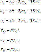
The main physical relationships in the problem of thermoelasticity are the Duhamel-Neumann equations, which have the form (Eq. 1):
 |
(1) |
where σx, σy, σz are the normal stresses, τxy, τxz, τyz are the shear stresses, Ɛx, Ɛy, Ɛz are the linear deformations, γxy, γxz, γyz are the shear deformations, λ = Ev/(1+v)(1-2v), µ = E/2(1+v), K = E/3(1-2v), θ = Ɛx + Ɛy + Ɛz is the volumetric deformation, ƐT = α(T-T 0) is the temperature deformation, α = 10-5 1/°C is the coefficient of linear thermal expansion of concrete, T is the current temperature at point, T 0 is the initial temperature, E is the modulus of elasticity of concrete, v is the Poisson's ratio of concrete.
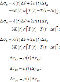
Mechanical characteristics λ, µ and K change in time t, so the relations (1) for the problem under consideration should be written in increments (Eq. 2):
 |
(2) |
In calculations of the thermal stress state for massive monolithic structures during the hardening process, it is generally assumed that the Poisson ratio of concrete ν is constant over time, and only its elastic modulus changes. The scientific hypothesis is that the problem of calculating the thermal stress state of a massive monolithic concrete structure with a time-varying elastic modulus can be reduced to the problem of calculating a structure with a constant elastic modulus E 0, to which an equivalent temperature effect is applied.
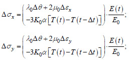
With a constant Poisson's ratio of concrete over time, equalities (2) can be represented as (Eq. 3):
 |
 |
(3) |
where λ = E 0v / (1+v)(1-2v), µ 0 = E 0 / 2(1+v), K 0 = E 0 / 3(1-2v).
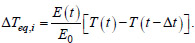
Let us assume that the increments of total deformations ∆Ɛx, ∆Ɛy, ∆Ɛz, ∆γxy, ∆γxz, ∆γ at each point of the structure over time ∆t are proportional to the change in temperature ∆T = [T(t)-T(t-∆t)] at the same point. Then the equivalent change in temperature ∆Teq,i over a period of time ∆t for a structure with a constant elastic modulus over time E 0, causing the same increase in stress as for a structure with a changing modulus of elasticity, can be calculated using the formula (Eq. 4):
 |
(4) |
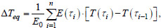
The equivalent change in temperature over the entire time period t can be determined using the formula (Eq. 5):
 |
(5) |
where n is the number of time steps,
 with a uniform time step.
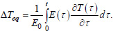
Formula (5) can also be represented as an integral (Eq. 6):
 |
(6) |
The calculation of the equivalent temperature change according to Eq. (6) is performed for each node of the structure after calculating the temperature field and determining the concrete modulus of elasticity at each moment in time.
2.2. Formulation of the Problem for Testing the Method
The proposed approach was tested on the example of a massive monolithic foundation slab 2 m thick, for which experimental data were presented [25], as well as the results of calculations in the DIANA FEA software package. A 0.1 m thick concrete base layer was made under the slab, below which a 10 m thick soil mass was located in the calculation model. The slab was made of concrete with a cement content of 240 kg/m3, cement class CEM III/A 32.5 N. The slab dimensions in plan were 26.5 × 41.5 m.
To determine the temperature field, a program in the MATLAB environment was developed by us that solves a three-dimensional problem of thermal conductivity using the finite element method. The thermophysical characteristics of concrete in the calculation were taken to be equal to: density ρ = 2349 kg/m3, specific heat capacity c = 1 kJ/(kg∙°C), thermal conductivity coefficient λ = 2.67 W/(m∙°C). The thermophysical characteristics of the soil had the following values: density ρ = 2070 kg/m3, specific heat capacity c = 1.039 kJ/(kg∙°C), thermal conductivity coefficient λ = 1.4 W/(m∙°C). The heat transfer coefficient on the upper surface of the slab, as well as on the upper surface of the soil massif, was taken to be equal to hup = 30 W/(m2 ∙ °C). On the side surfaces of the slab, covered by formwork, the heat transfer coefficient was taken to be equal to hside = 8 W/(m2 °C).
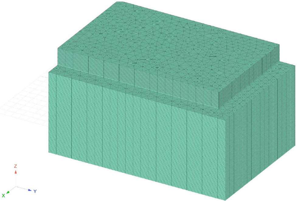
At points of the soil massif, sufficiently distant from the foundation slab, the temperature was taken as given and equal to the initial soil temperature Tbot = 16 °C. The initial temperature of the concrete mixture was taken to be T0 = 24 ° C. For the calculation in MATLAB, finite elements in the form of triangular prisms were used. The dimensions of the triangle's sides at the base of the prism were taken to be 1 m. The foundation slab was divided into 40 finite elements by thickness, and the soil massif was divided into 100 finite elements. Due to the symmetry of the problem, a quarter of the structure was considered. The finite element mesh is shown in Fig. (1).
The specific power of internal heat generation (W/m3) was set based on the work of S.V. Aleksandrovsky [36], by Eq. (7):
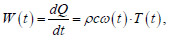 |
(7) |
where
 θ 0 = 20°C is the initial temperature of laboratory adiabatic tests to determine the heat release of concrete, B is the constant determining the rate of heat release,
 is the maximum temperature of the adiabatic process, determined by Eq. (8):
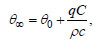 |
(8) |
where q is the maximum amount of heat released by 1 kg of cement in an adiabatic process (J/kg), C is the cement consumption (kg/m3).
The calculation was performed at q = 320 kJ/kg, B = 7 ∙ 10 -4 1/(°C ∙ h).
The heat conductivity equation, taking into account Eq. (8), takes the form (Eq. 9):
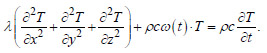 |
(9) |
From Eq. (9), it is evident that heat release at each moment of time depends on temperature. This approach allows us to take into account that with increasing temperature, the rate of cement hydration chemical reaction increases, and the rate of heat release accordingly also increases. In order not to include the multiplier before the temperature in Eq. (9) in the matrix of coefficients in the system of FEM equations, the heat release power at time t was determined by the temperature at the previous step T(t-∆t) . With a small time step, such a technique is acceptable and does not lead to significant errors.
The ambient temperature was taken in accordance with the data of in-situ measurements, which are shown in Fig. (2). When calculating the stress-strain state, the modulus of elasticity of concrete was taken as a function of its equivalent age teq as in work (Eq. 10) [25]:
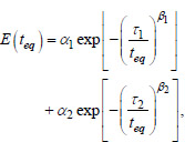 |
(10) |
where α1 = 15 GPa, α2 = 20 GPa, t1= 2 days, τ2= 4 days, β1 = β2 = 1.5.
The equivalent age was determined using Eq. (11):
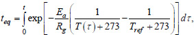 |
(11) |
where Ea is the activation energy, Rg is the universal gas constant, Tref = 20°C.
The ratio of Ea/Rg was taken to be equal to 4630 J/K.
Finite element mesh in MATLAB.
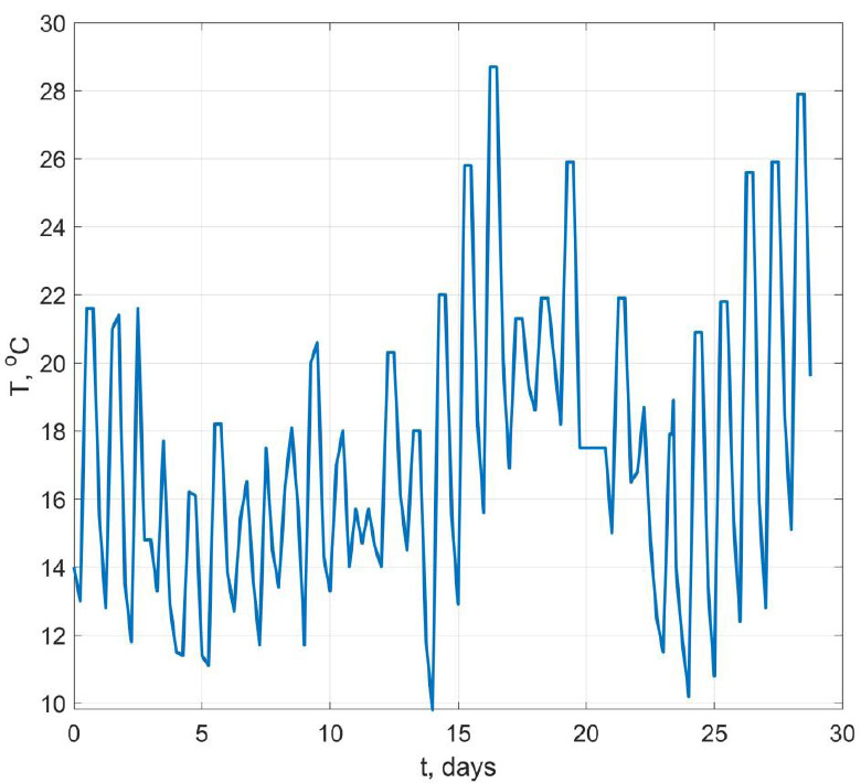
Change in ambient temperature over time.
The soil modulus of elasticity in the stress-strain state calculations was taken to be 30 MPa, and the Poisson's ratio was v = 0.2. After determining the temperature field in MATLAB, the equivalent temperature load on each finite element of the foundation slab was calculated, and then the finite element model was transferred to the Lira-SAPR 2017 software package using a text file in the “.txt” format generated in MATLAB.
The flowchart reflecting the calculation sequence is shown in Fig. (3).
3. RESULTS
Fig. (4) shows a comparison of experimental and calculated temperatures in the center of the foundation slab at a distance of 5 cm from its lower surface and in the middle of the thickness.
The maximum temperature according to the calculation results is 45.3 °C, and according to the experimental results, it is 44.3 °C. Good agreement between the calculation results and the experiment is observed throughout the entire process under study, both in the middle of the thickness and at the lower surface. The coefficient of determination R2 between the experimental and calculated temperatures is 0.92 for the values in the middle of the thickness and 0.96 for the values in the bottom of the slab. Such an agreement was achieved by taking into account the effect of concrete temperature on the rate of heat release. Note that it is impossible to consider this factor using standard FEM complexes such as ANSYS, Abaqus, etc.
Table 1 shows the influence of the finite element mesh size on the maximum temperature. hz in this table is the size of the finite element along the z axis. hxy is the size of the triangle side in the xy plane. From Table 1, it can be seen that the size of the finite element along the z-axis has a more significant effect on the result than the size of the triangle side. This is explained by the fact that in foundation slabs, with the exception of the edges, the temperature distribution is close to one-dimensional: the change occurs only along the z axis. Fig. (5) shows the dependence of the maximum temperature on the number of finite elements across the slab thickness at hxy = 1 m. Finally, when calculating the thermal stresses, the values hz = 0.05 m and hxy = 1 m were adopted.
| hz, m | 0.4 | 0.4 | 0.4 | 0.2 | 0.2 | 0.2 | 0.1 | 0.1 | 0.05 |
| hxy, m | 8 | 4 | 2 | 4 | 2 | 1 | 2 | 1 | 1 |
| Tmax, °C | 46.19 | 46.12 | 46.35 | 45.50 | 45.52 | 45.52 | 45.37 | 45.37 | 45.28 |
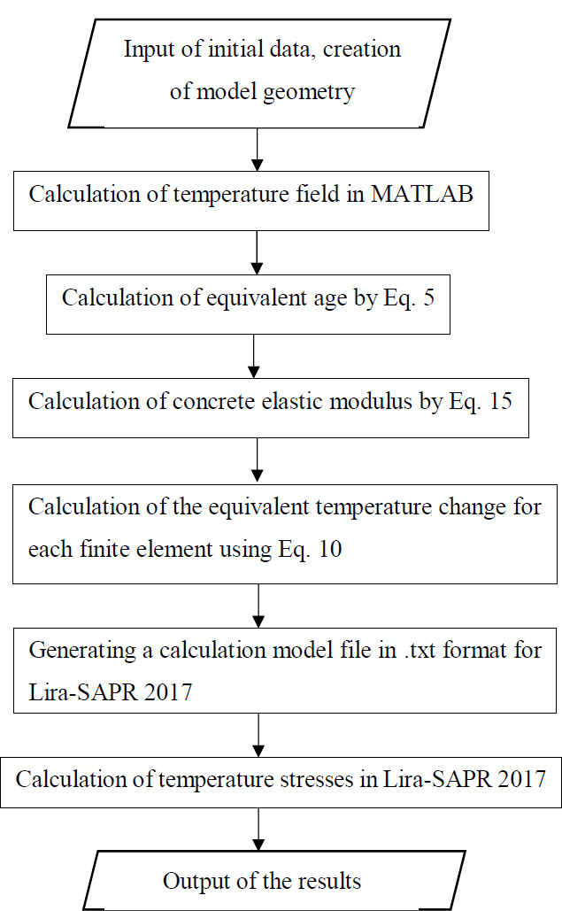
Calculation flowchart.
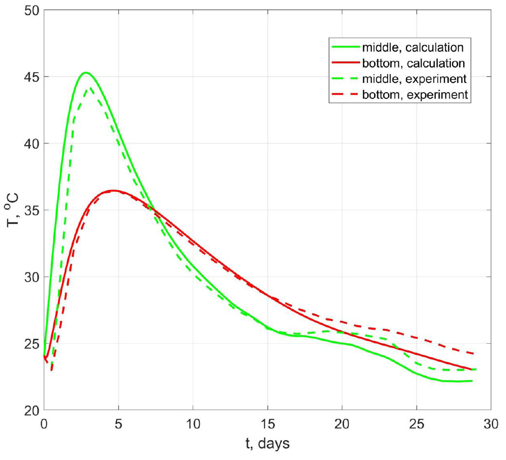
Comparison of experimental and calculated temperatures in the middle of the foundation slab and at the bottom surface.
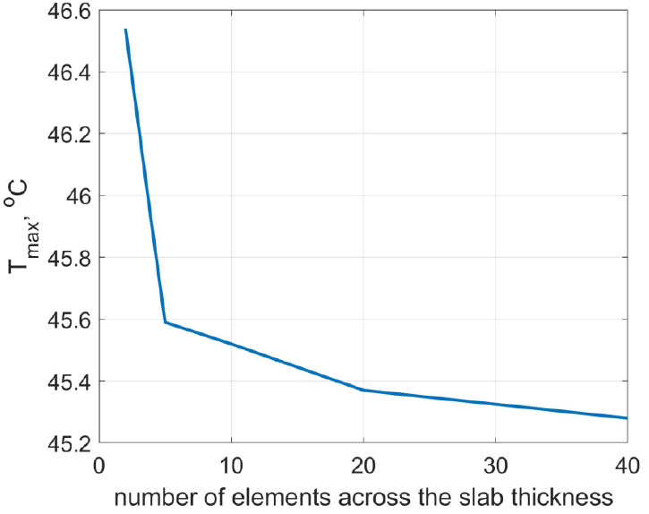
Convergence study.
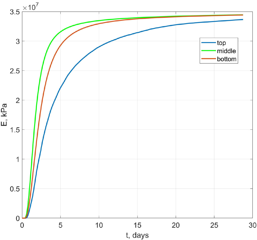
Change in time of the concrete elastic modulus.
Fig. (6) shows graphs of the concrete elastic modulus change in time for the upper surface of the slab, the middle of the thickness, and the lower surface in its center. From these graphs, it is evident that the temperature regime of hardening significantly affects the kinetics of the deformation characteristics.
Fig. (7) shows the change in time of the values ∆Teq for the center of the slab, the middle, and the lower surface at the central point. The calculations were performed at E 0 =2.104 MPa. Most of the curves for the middle and the bottom of the slab are in the zone of negative temperatures, since the cooling of the slab occurs at greater values of the concrete elastic modulus than its heating. A comparison of the calculated stresses σx obtained by our method with the experimental results, as well as the results is shown in Fig. (8) [25]. From Fig. (8), it is evident that the discrepancy between the calculation results by our method and the results given in [25] is insignificant. Good agreement with the experimental data is observed up to 6 days. Further deviation may be associated with the effects of creep and shrinkage, as well as the discrepancy between the used dependence of the change in the elastic modulus of concrete over time and real conditions.
In contrast to the method described in study "Methodology for determining true temperature stresses during the construction of massive monolithic reinforced concrete structures", the approach we propose allows us to determine the true stresses not at a specific point, but at all points of the structure [35]. Fig. (9) shows the stress σx isofields in the middle layer of the slab for the time moment t = 690 h, obtained in the Lira-SAPR 2017 program after transferring the calculation scheme with equivalent loads to it. The planes of symmetry pass along the lower and left side of the plan. From Fig. (9), it is evident that, with the exception of the edges, the stress field is uniform. Local spikes are observed at the edges, caused by changes in the boundary conditions.
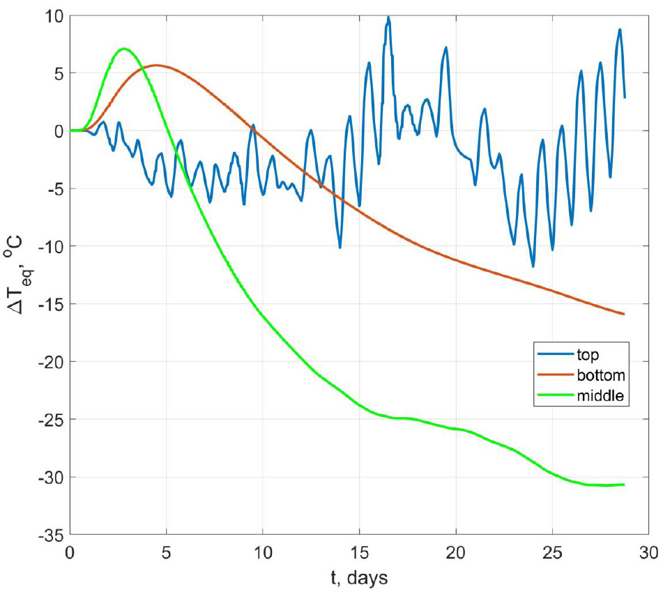
Change in time of the value ∆Teq for the lower surface, middle, and upper surface of the slab.
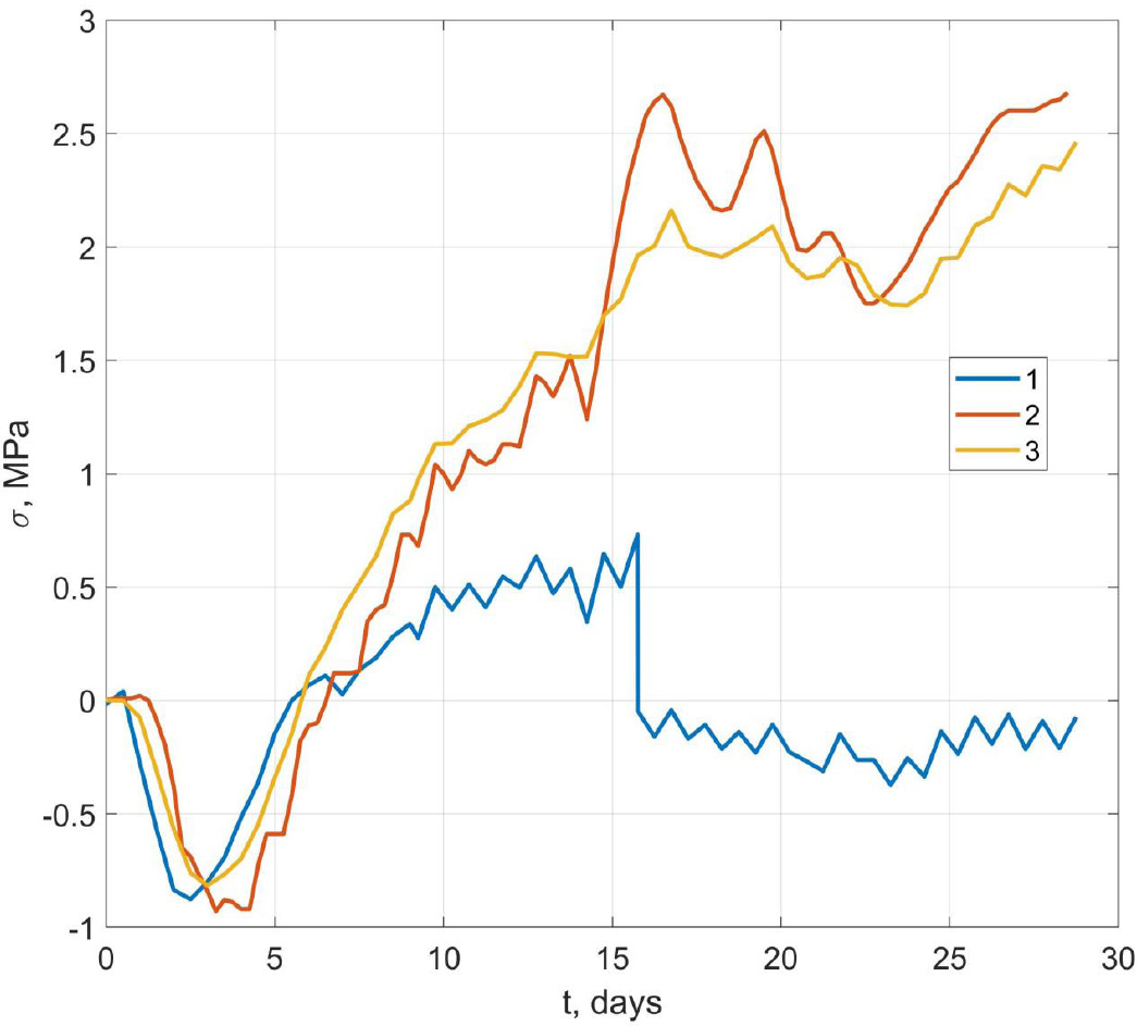
Comparison of the experimental results (line 1) with the calculation results using the proposed method (line 3) and the calculation results given in (line 2) [25].
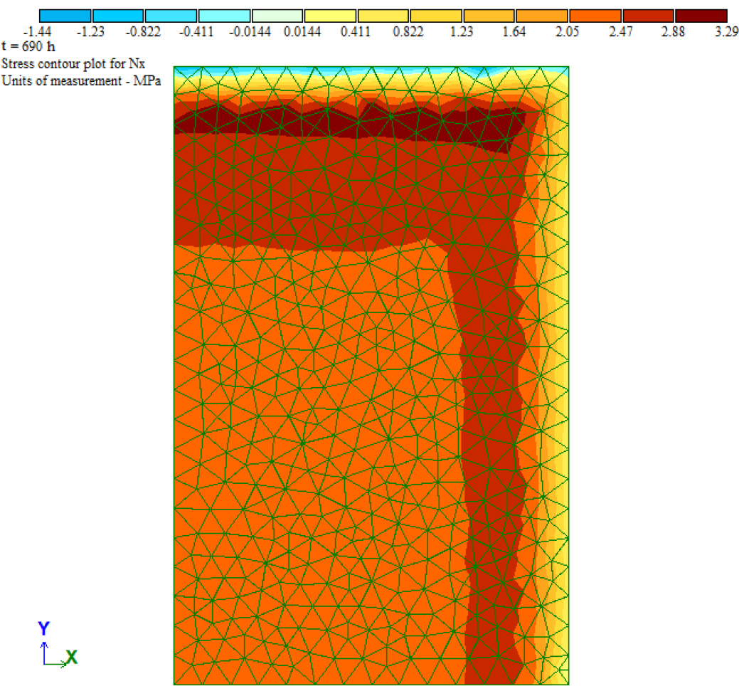
Stress σx isofields in Lira - SAPR 2017 at t = 690 h.
4. DISCUSSION
A number of authors propose expressing temperature stresses through the maximum temperature difference between the center and surface of the structure using formulas of the following type (Eq. 12) [37-41]:
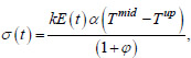 |
(12) |
where k is the deformation limitation coefficient, ϕ is the concrete creep coefficient, Tmid and Tup are, respectively, the temperature at the center and on the surface of the foundation slab.
Fig. (10) shows graphs of the change in time of the actual Tup-Tmid and equivalent
 temperature difference between the center and the upper surface of the structure. It is evident from Fig. (10) that the curve
 by its nature repeats the stress change curves shown in Fig. (8). Thus, when assessing the crack resistance of massive monolithic foundation slabs and walls, the value of not the actual, but the equivalent temperature difference between the center and the surface of the structure should be used.
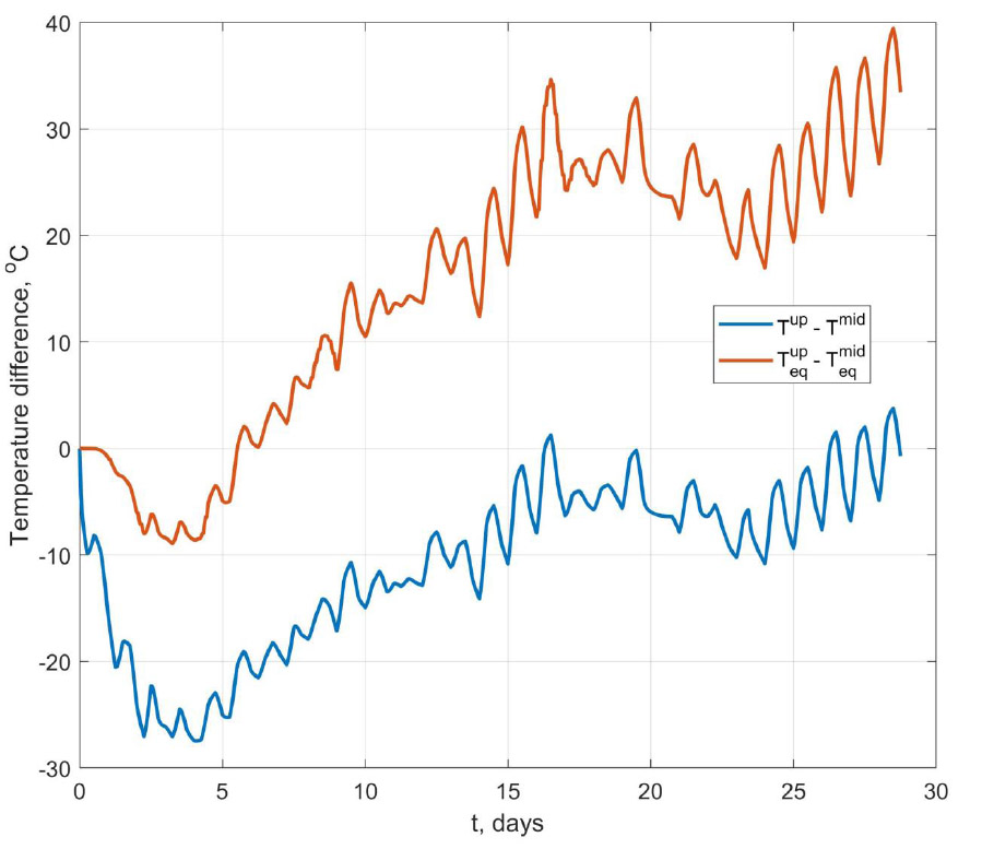
Change in time of the actual and equivalent temperature difference between the center and the surface of the structure.
5. LIMITATIONS
The proposed approach does not yet allow for the creep and shrinkage deformations of concrete to be taken into account. It is also not clear yet how reliable the method will be in the case where the structure is erected on a foundation made of old concrete. In addition, most of the concrete elastic modulus time dependences give reliable results at an age of more than 1 day.
CONCLUSION
The main research findings are as follows:
1. A new effective method was proposed for calculating thermal stresses in hardening mass concrete during construction. The idea of the method is that instead of a structure with a time-varying modulus of elasticity, it is possible to calculate a structure with a constant modulus of elasticity by replacing the actual temperature load (temperature difference) with an equivalent one. This approach allows calculating the thermal stress state of massive monolithic structures during construction using standard finite element programs, which by default cannot take into account changes in the deformation characteristics of concrete over time. The efficiency of the proposed method is due to the fact that it does not require the recalculation of the structure stiffness matrix at each time step. This approach ensures significant savings in computational resources.
2. The proposed approach has been tested by comparison with experimental data and the results of the calculation of a massive foundation slab [25]. The results are in satisfactory agreement with the experimental data. In the first 6 days, when the risk of early crack formation is most significant, the discrepancy with the experiment in terms of maximum stress values does not exceed 5%.
3. It was shown that temperature stresses at each moment in time should be expressed not through the actual, but through the equivalent temperature difference between the center and the surface of the structure.
RECOMMENDATIONS FOR FUTURE RESEARCH
Further studies may be aimed at clarifying the dependencies of changes in the deformation characteristics of concrete in early age, as well as taking into account the effects of creep and shrinkage when determining the equivalent load. The issue of interaction between fresh concrete and the base made of old concrete also requires special attention.
AUTHOR’S CONTRIBUTIONS
The authors confirm contribution to the paper as follows: A.C.: Conceived and designed the study; V.T.: Developed software and conducted analysis; D.T.: Drafted the manuscript. All authors reviewed the results and approved the final version of the manuscript. All authors have read and agreed to the published version of the manuscript.
ABBREVIATION
| FEM | = Most Finite Element Method |
AVAILABILITY OF DATA AND MATERIALS
The data supporting the findings of the article is available within the article.
FUNDING
The study was supported by the grant of the Russian Science Foundation, Russia No. 25-19-00164, https://rscf.ru/project/25-19-00164/.
ACKNOWLEDGEMENTS
The authors would like to acknowledge the administration of Don State Technical University, Russia, for their resources and the Russian Science Foundation for facilitating this research.

