All published articles of this journal are available on ScienceDirect.

Investigation of Steel Frames Equipped with Steel Eccentric Braces and Steel-Concrete Buckling-Restrained Braces Having Moment Link
Abstract
Background:
Different bracing systems of steel Eccentric Braces (EBs) and steel-concrete Buckling-Restrained Braces (BRBs) can be used in steel frames in order to make the frames stronger in resisting lateral loads. These steel frames with EBs or BRBs are generally called Eccentrically Braced Frames (EBFs) or Buckling-Restrained Braced Frames (BRBFs), respectively.
Objective:
This study aims to investigate steel frames with bracing systems of steel EBs and steel-concrete BRBs having moment link.
Methods:
The EBFs and BRBFs are nonlinearly analysed employing the finite element software ABAQUS. Experimental tests of the EBF and BRB are utilised for the validation of their modelling. The modelling is validated by comparing the modelling results with experimental tests results. Then, an EBF and a BRBF are designed having moment link. The extreme earthquake records of Tabas, Chi-Chi, and Northridge are selected for the dynamic analyses of the EBF and BRBF. The validated modelling method is applied to analyse the designed EBF and BRBF under the selected earthquake records.
Results:
The achieved results from the analyses are lateral displacements, base shears, and energy dissipations of the EBF and BRBF and moment link rotations. These results are compared and discussed.
Conclusion:
It is concluded that the hierarchy of the lateral displacements of the analysed EBF and BRBF, having moment link, is related to the Tabas, Chi-Chi, and Northridge records because the lateral displacements of the frames are directly proportional to the peak ground accelerations of the records, and there is the same hierarchy for the records in terms of their peak ground accelerations. Lower lateral displacements are witnessed for the BRBF than the EBF subjected to the Tabas and Chi-Chi records. However, larger lateral displacement is observed for the BRBF than the EBF under the Northridge record. The same procedure as the lateral displacements is also revealed for the effectiveness of the BRBF with regard to its link rotations compared with the EBF. Moreover, the BRBF improves the base shear capacities and energy dissipations of the frame compared with the EBF. Consequently, the BRBF is generally demonstrated to be superior to the EBF from the structural performance point of view. Thus, the BRBF can be used more efficiently in structures subjected to large lateral loads compared with the EBF.
1. INTRODUCTION
Two performance objectives are the basis of the design of steel buildings for earthquake loads. These objectives are the elastic response during minor to moderate earthquakes and collapse prevention during extreme earthquakes. In order to obtain these objectives for buildings under minor to moderate earthquakes, they are designed with enough lateral stiffness to limit large displacements. Also, to meet these objectives for buildings subjected to extreme earthquakes, they are designed with enough ductility to withstand large inelastic displacements and to prevent collapse. This kind of design of buildings is often accomplished by applying ductile braced frame systems. These systems have both great lateral stiffness and ductility.
A bracing element provides high lateral stiffness. An inelastic mechanism which is especially designed to isolate frame damage during overloading offers ductility. Steel frames with steel Eccentric Braces (EBs) or steel-concrete Buckling-Restrained Braces (BRBs), which are respectively called Eccentrically Braced Frames (EBFs) or Buckling-Restrained Braced Frames (BRBFs), are common types of ductile braced frame systems.
The EBFs dissipate energy as stiffened beam segments, called links, which rotate inelastically under extreme earthquake loading. The BRBFs consist of a steel core confined in a concrete-filled steel tube. The lateral forces are axially resisted by the core, while the buckling of the core is prevented by the concrete confinement. Thus, the BRBFs dissipate energy through the axial yielding of the BRB core. BRBs behave equally well in tension and compression. The balanced hysteretic behaviour of the BRBs provides greater ductility than the traditional braces that are limited by poor post-buckling resistance to compressive loads [1].
Links in the EBFs and BRBFs are formed by eccentricities between two braces connections. Very large moment and less shear are developed by the flexural yielding link, moment link, with the link length according to equation (1):
 |
(1) |
where, e, Mp, and Vp are the link length, plastic moment capacity, and plastic shear capacity of the link section, respectively.
Research projects have been conducted on the EBFs [2-14] and BRBFs [15-28] during recent decades. Also, a hybrid monitoring technique, which was on the basis of the capture and analysis of a digital image set, was presented for measuring the deformation field in order to achieve information about crack propagation in structures to monitor their state of health [29]. Whilst, the present study investigates the EBFs and BRBFs with the moment link under three different extreme earthquake loads.
This paper deals with the investigation of the steel EBFs and steel-concrete BRBFs having moment link under the extreme earthquake records of Tabas, Chi-Chi, and Northridge. ABAQUS is employed to perform the nonlinear dynamic analyses of the EBFs and BRBFs. The modelling verification of this study is established by comparison of its results with those of the experimental tests. The verified modelling is then utilised to analyse the designed EBF and BRBF having moment link under the earthquake records. The obtained results from the nonlinear analyses are compared and discussed.
2. MATERIALS AND METHODS
Since the accuracy of modelling the EBF and BRBF is needed to be achieved, the experimental tests of the EBF and BRB are explained and modelled here. After the demonstration of the modelling accuracy, an EBF and a BRBF are designed having moment link. Then, three extreme earthquake records of Tabas, Chi-Chi, and Northridge are selected for further analyses. Finally, the designed EBF and BRBF are analysed while being subjected to these earthquake loads.
2.1. EBF
2.1.1. Experimental Test of EBF
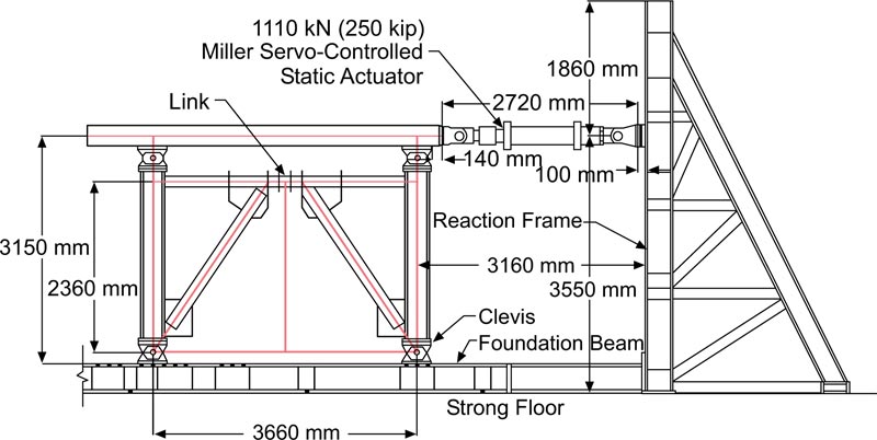
A steel EBF, which was tested experimentally [30], was modelled to establish the verification of the modelling. The EBF had a hollow rectangular cross-section. Fig. (1) shows the setup of the experimental test of the EBF. The overall height and width (L) of the test specimen were 3150 mm and 3660 mm, respectively. A hydraulic actuator was employed to transfer the horizontal force to a loading beam. The beam distributed the load to clevises equally at the top of each column. The guidelines of ATC-24 [31] were followed for the loading protocol. The steel of the link was A572 Gr. 50, having a nominal yield strength of 345 MPa. HSS 178 × 178 × 12.7 (US-7 × 7 × 1/2) and W 310 × 143 (US-12 × 96) were utilised for the braces and columns, respectively. Pinned supports were used for the columns' ends. The moment resisting connections were applied between the beam, columns, and braces.
2.1.2. Modelling EBF and Accuracy of Modelling
In this section, modelling the EBF using the ABAQUS software is explained. ABAQUS is a highly powerful modelling software based on the finite element method and is capable of solving problems from simple linear analysis to the most complex nonlinear modelling. This software consists of a very large set of elements so that any type of geometry can be modelled by these elements. It also has many models of engineering materials that can be utilised in modelling a variety of materials with different properties and behaviours, such as steel and concrete.
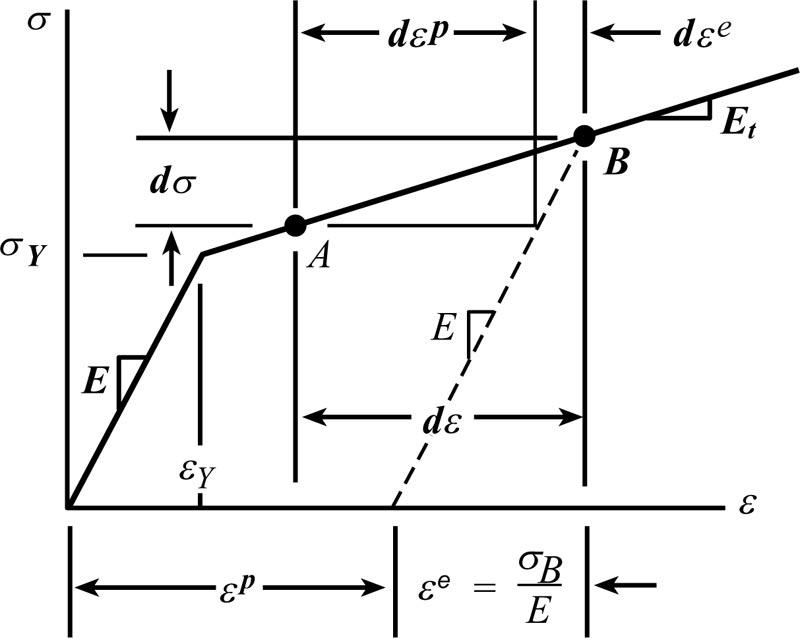
To model the members of the EBF specimen, the 4-node shell element S4R was used. The steel material was modelled, taking into account its features. A bilinear model was considered for the steel, which had kinematic hardening behaviour to take the progressive hardening and softening effects into consideration. The used steel material model is displayed in Fig. (2). σ was the uniaxial stress and ε was its corresponding axial strain. For strains larger than εY, a strain increment dε consisted of an elastic contribution dεe and a plastic contribution dεp.
All the characteristics of the experimentally tested EBF, which were mentioned in section 2.1.1, were considered in the modelling. Since the size of the mesh had considerable effects on the modelling results, different mesh sizes were tried for the model and their results were compared. From the conducted convergence study on the mesh size of the modelling, it was concluded that the mesh size of 50 mm could accomplish accurate results. Thus, this mesh size was adopted for the modelling.
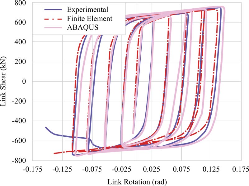
To establish the modelling accuracy, the link shear-link rotation graph was achieved from the modelling result (ABAQUS) in this study to compare it with those of the experimental test and finite element [30]. These comparisons are illustrated in Fig. (3). Considering the existence of a very good agreement between the results in Fig. (3) from their behavioural viewpoint and values, modelling the EBF was verified.
2.1.3. Design of EBF Having Moment Link
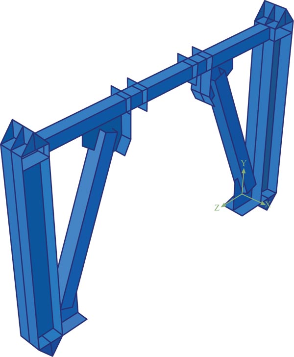
The geometry of the EBF was the same as that in the modelling accuracy, however, the link was designed to have the flexural yielding behaviour following equation (1). Based on the design, the length of the moment link was found to be 120 cm. Fig. (4) indicates the modelled EBF having moment link.
2.2. BRBF
2.2.1. Experimental Test of BRB
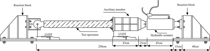
To reveal the accuracy of modelling the BRBF, an experimentally tested BRB [33] was modelled here. In the test, the length of the BRB was 60 cm. The cross-sections of the steel core and steel tube were 80 × 8 mm and 120 × 120 × 3 mm, respectively. The setup of the experimental test of the BRB is presented in Fig. (5). As can be observed from the figure, the setup included a test specimen, a hydraulic actuator, two end reaction blocks, and an auxiliary rigid member for facilitating the specimen fitting. Two LVDTs, as the global displacement instrumentation, were placed at the ends of the specimen. Further, the strain gauges, as the local instrumentation, were installed throughout the specimen. The connections were made using pin. The specimen was tested under the cyclic load based on the recommendations mentioned in FEMA 450 [34]. The yield stresses of the steel core and steel tube were 297.5 MPa and 370 MPa, respectively. The compressive strength of the concrete at 28 days was 30 MPa.
2.2.2. Modelling BRB and Accuracy of Modelling
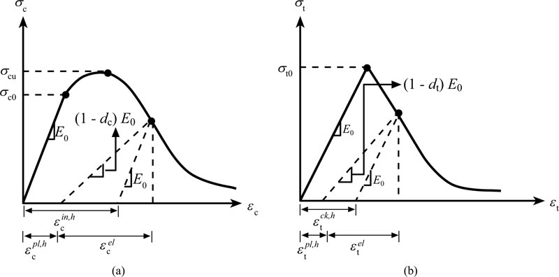
The steel material of the BRB was modelled similar to section 2.1.2. The concrete was modelled using the concrete material damage plasticity model as depicted in Fig. (6). The total strain tensor ε was composed of the elastic part εel and the plastic part εpl. dt and dc were two scalar damage parameters, which were ranged from 0 (undamaged) to 1 (fully damaged). Isotropic hardening parameters were represented by the inelastic compression strain  and the cracking strain
  which were comprised of the plastic hardening strain εpl,h plus the residual strain owing to damages. The damage states in compression and tension were respectively expressed by two hardening parameters
  and
and  which indicated the equivalent plastic strains in compression and tension, respectively. σc, εc, and σcuwere the nominal compressive stress, nominal compressive strain, and ultimate compressive strength of the unconfined cylinder specimen, respectively. 7% to 10% of the ultimate compressive strength σcu is generally taken as tensile strength, σt0 , hence, the maximum value was considered for σt0 as 0.1σcu in the current research. σt was the uniaxial tensile response of the concrete with regard to the concrete model under tension load, while εt was its corresponding strain. E0 was the modulus of elasticity.
The shell element S4R was considered for modelling the steel tube, while the solid element C3D8R was taken into account for modelling the steel core and concrete. All the features of the tested BRB in section 2.2.1 were adopted in the modelling. The suitable mesh size was resulted from the convergence study on the model of the BRB, which accomplished accurate result.
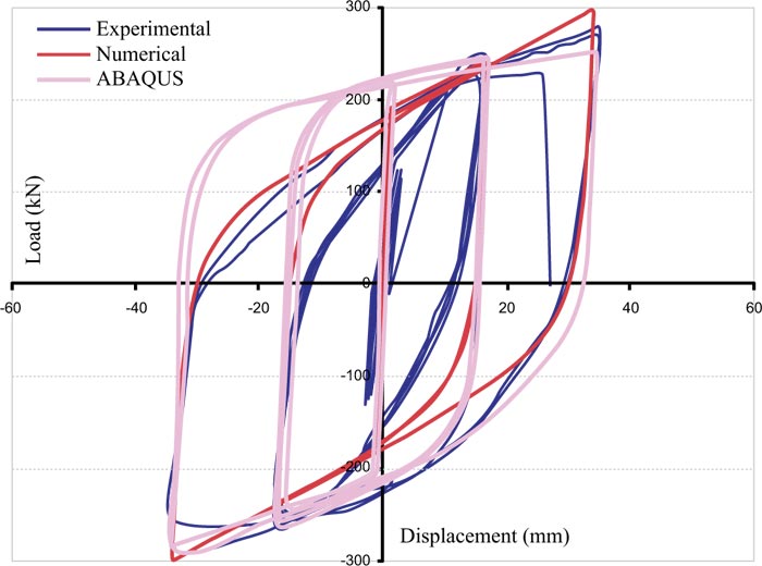
To demonstrate the accuracy of the modelling, the modelling result (ABAQUS) of the current study was compared with the results of the experimental test and numerical analysis [33]. Based on the similar behaviours and close values resulted from the comparison of the curves in Fig. (7), the accuracy of modelling the BRB was uncovered.
2.2.3. Design of BRBF Having Moment Link
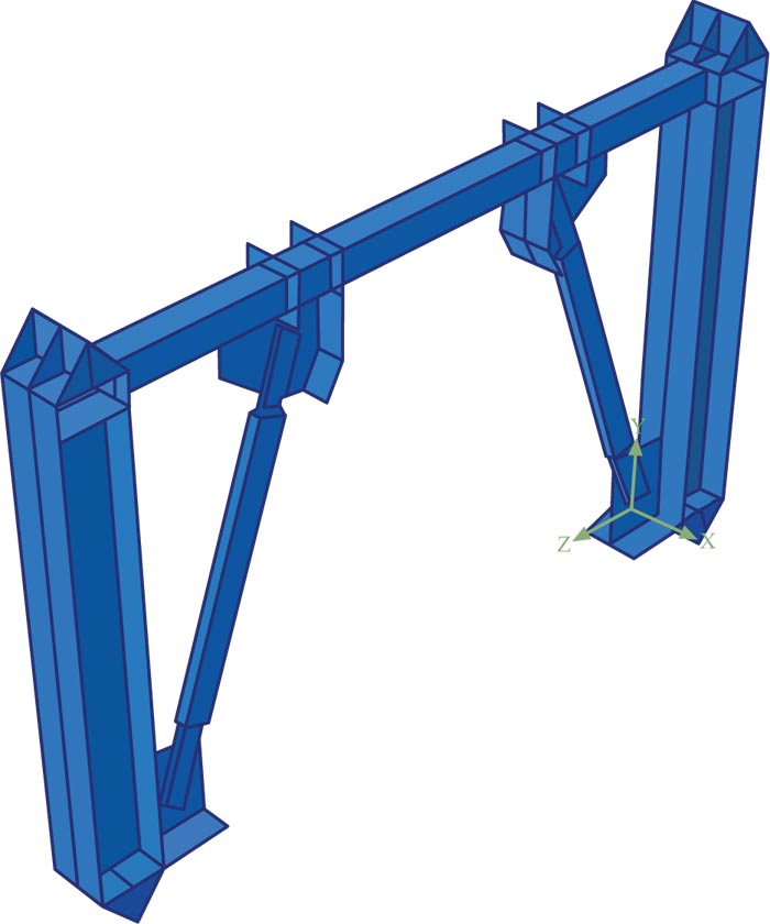
The geometries of the frame and moment link length are like those of the EBF in this study, while the braces are BRB here. Following the verified modelling method, the BRBF with moment link was modelled considering all the specifications in section 2.2.1. The modelled BRBF with moment link is displayed in Fig. (8).
3. EARTHQUAKE RECORDS
Three different extreme earthquake records of Tabas, Chi-Chi, and Northridge were selected to load the modelled EBF and BRBF in their analyses. Characteristics of these records are summarised in Table 1. Mw, PGA, PGV, and PGD, respectively denote the magnitude of the earthquake, peak ground acceleration, peak ground velocity, and peak ground displacement.
4. ANALYSIS OF EBF AND BRBF HAVING MOMENT LINK
The EBF and BRBF with moment link, which were respectively designed in sections 2.1.3 and 2.2.3, were analysed nonlinearly under the earthquake records of Tabas, Chi-Chi, and Northridge. The results obtained from these analyses are presented and discussed in the following.
5. RESULTS AND DISCUSSION
The results are represented as the lateral displacements, base shears, and energy dissipations of the EBF and BRBF, and their moment link rotations below. Also, Table 2 lists the results achieved from the analyses of the EBF and BRBF.
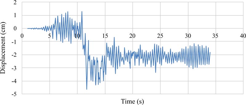
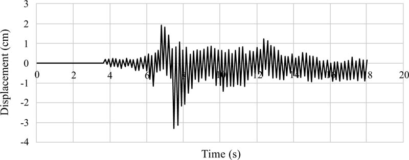
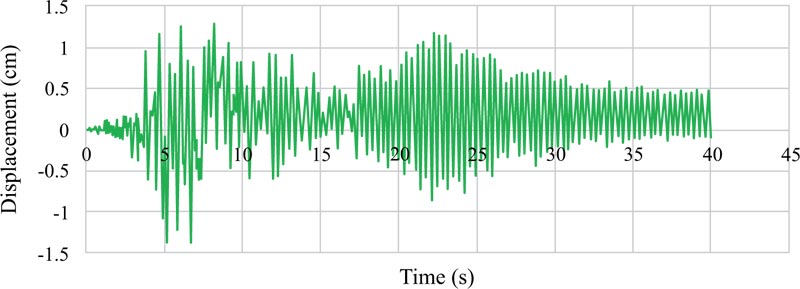
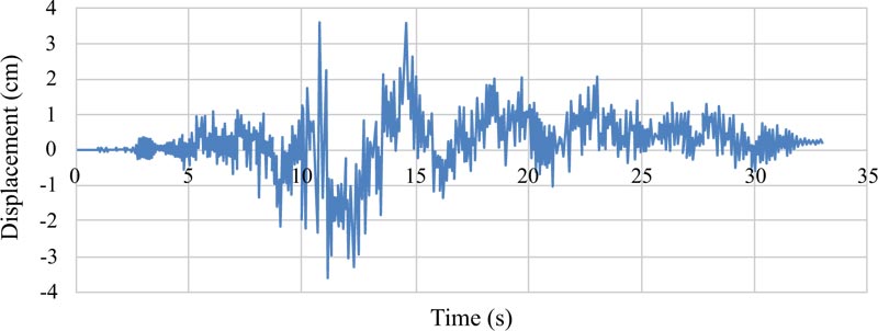
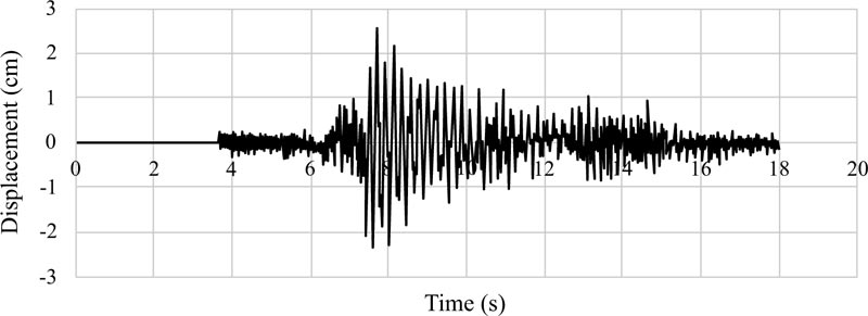
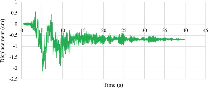
5.1. Lateral Displacements of EBF and BRBF Having Moment Link
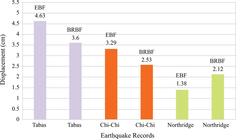
Graphs of the lateral displacements of the EBF and BRBF are shown in Figs. (9-11 and 12-14), respectively. According to Table 1, the hierarchy of the records in terms of the peak ground acceleration was Tabas, Chi-Chi, and Northridge. The same hierarchy could also be observed for the lateral displacements of the EBF and BRBF in the figures because there is a direct relationship between the lateral displacements of the frames and the peak ground accelerations of the records. Also, comparison of the maximum lateral displacements of the EBF and BRBF is illustrated in Fig. (15). Under the Tabas and Chi-Chi records, the BRBF experienced lower lateral displacements than the EBF because the BRBF had greater stiffness than the EBF, which reduced the lateral displacement of the frame and led to the desired conclusion. However, the BRBF under the Northridge record resulted in larger lateral displacement than its corresponding EBF because many other parameters, such as the ratio of the structure frequency to the earthquake frequency, the record duration, and the earthquake energy, can also affect the dynamic response of structures. Therefore, these parameters bring many uncertainties in the prediction of the dynamic performance of the structures.
| Earthquake | Year | Mw (Richter Scale) | PGA (g) | PGV (cm/s) | PGD (cm) |
| Northridge | 1994 | 6.70 | 0.349 | 32.25 | 9.30 |
| Chi-Chi | 1999 | 7.70 | 0.89 | 98 | 15.85 |
| Tabas | 1978 | 7.40 | 0.928 | 111.35 | 91.10 |
| Bracing System | Earthquake | Maximum Lateral Displacement (cm) | Maximum Base Shear (kN) | Maximum Energy Dissipation (kN-cm) | Maximum Link Rotation (rad) |
| EBF | Tabas | 4.63 | 3143 | 46159 | 5.2 |
| Chi-Chi | 3.29 | 2700 | 1847 | 3.7 | |
| Northridge | 1.38 | 2767 | 16719 | 1.5 | |
| BRBF | Tabas | 3.6 | 7719 | 94823 | 4 |
| Chi-Chi | 2.53 | 3587 | 3876 | 2.8 | |
| Northridge | 2.12 | 3721 | 29706 | 4.8 |
One of the most important characteristics of the near-fault earthquakes is the existence of pulses with large amplitudes, especially in the velocity-time history. These pulses apply a lot of energy to the structure during a short period of time, which causes the structure to dissipate this energy with large displacements.
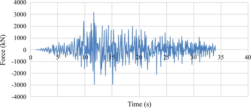
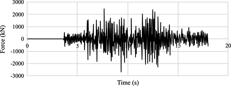
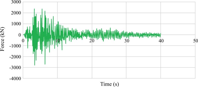
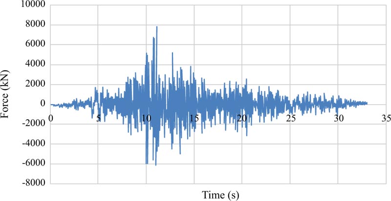
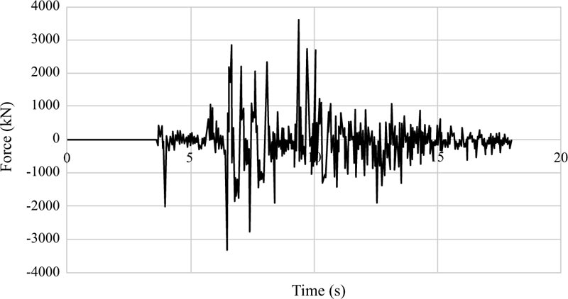
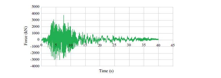
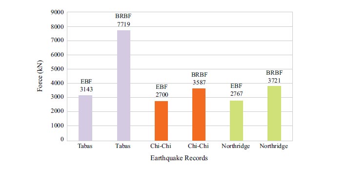
5.2. Base Shears of EBF and BRBF Having Moment Link
Figs. (16-18 and 19-21) depict the base shear graphs of the EBF and BRBF, respectively. Also, Fig. (22) compares their maximum base shears. In accordance with Fig. (22), the maximum base shears of the EBF under Tabas, Chi-Chi, and Northridge records were 3143 kN, 2700 kN, and 2767 kN, which were respectively improved to 7719 kN, 3587 kN, and 3721 kN by using the BRBF under the same records. This issue revealed the effectiveness of utilising the BRBF in increasing the base shear capacity of the frame compared with the EBF since the failure modes of the EBF and BRBF were different in which the EBF failed mainly due to buckling of the braces while the BRBF failed because the steel core of the braces became hinged at the location of the connections. Also, the failure of the BRBF was delayed compared with the EBF. These reasons led to more efficient use of the structural capacity of the BRBF compared with the EBF.
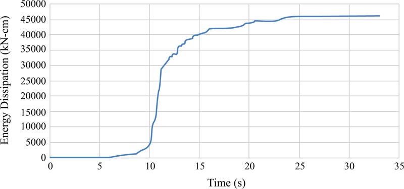
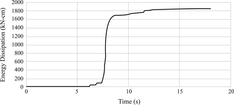
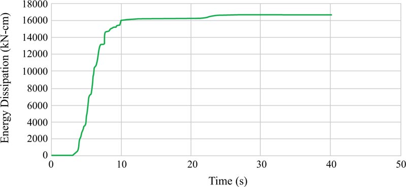
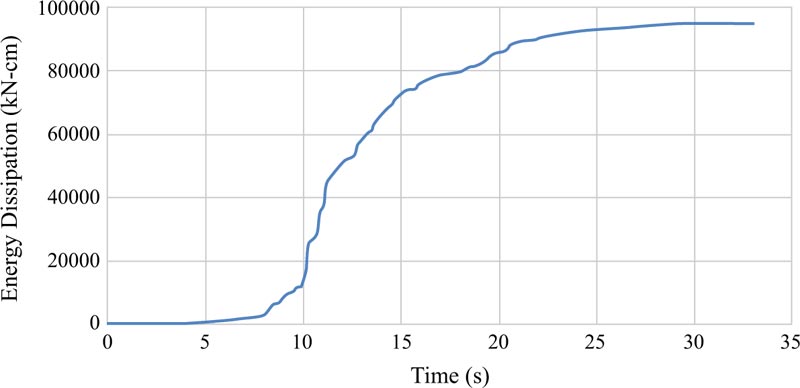
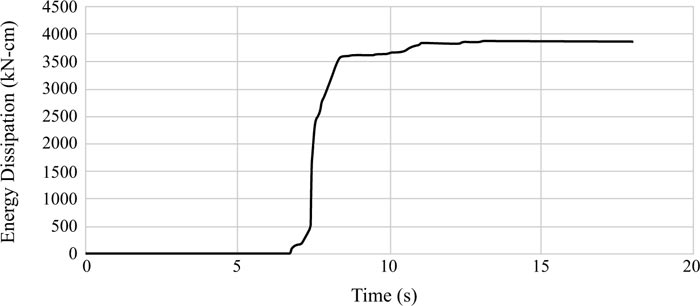
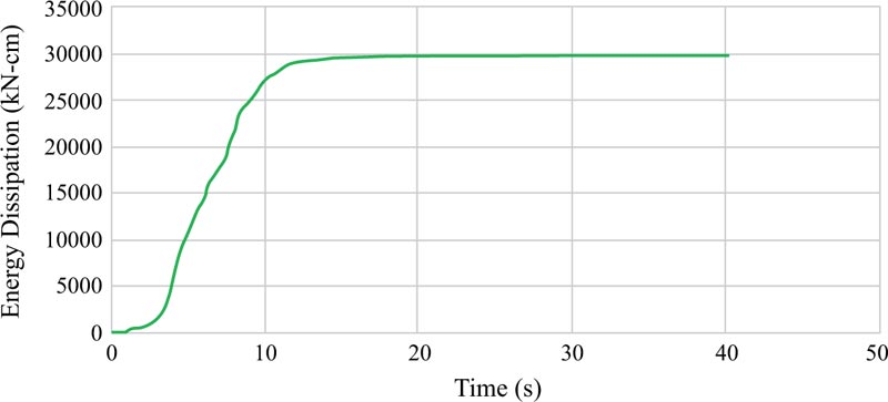
5.3. Energy Dissipations of EBF and BRBF Having Moment Link
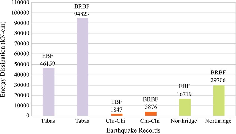
Energy dissipations are other results achieved from the analyses of the EBF and BRBF and their graphs are elaborated in Figs. (23-25 and 26-28), respectively. Fig. (29) clarifies that the maximum energy dissipations of the EBF subjected to the Tabas, Chi-Chi, and Northridge records are 46159 kN-cm, 1847 kN-cm, and 16719 kN-cm, however, the maximum energy dissipations of the BRBF under the same records are 94823 kN-cm, 3876 kN-cm, and 29706 kN-cm, respectively. Comparing these maximum energy dissipations concluded that as the BRBF was used, the energy dissipations of the frame were enhanced compared with the EBF.
5.4. Rotations of Moment Link of EBF and BRBF
The rotations of the moment link of the EBF and BRBF were calculated using equation (2):
 |
(2) |
where, L, e, Δ, and h are the frame span length, link length, frame lateral displacement, and frame height, respectively.
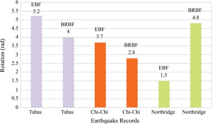
Fig. (30) displays the comparison of the maximum moment link rotations of the EBF and BRBF. The figure obviously expresses that utilising the BRBF generally reduced the link rotations compared with the EBF. The largeness of the link rotations of both EBF and BRBF was respectively related to the Tabas, Chi-Chi, and Northridge earthquake loads. This hierarchy of the rotations was also witnessed for the lateral displacements of the EBF and BRBF in section 5.1 because, according to equation (2), the link rotation and the lateral displacement of the frame has a direct proportion. It is noteworthy that the same uncertainties in the predictions described for the lateral displacements in section 5.1 also existed for the link rotations, in which the BRBF had larger link rotation than the EBF under the Northridge record.
CONCLUSION
Different bracing systems of steel EBs and steel-concrete BRBs were utilised for the steel frames having moment link in this research. The ABAQUS software was employed for the nonlinear finite element analyses of the EBF and BRBF. Experimental tests of EBF and BRB were selected for the validation of modelling. These experimentally tested EBF and BRB were modelled, considering all of their features. Then, these models were analysed nonlinearly and their results were achieved. The accuracy of the models was accomplished by comparing the results of modelling the EBF and BRB with their corresponding experimental tests results. Afterwards, an EBF and a BRBF were also designed having moment link. The verified modelling method was followed to analyse the designed EBF and BRBF under the earthquake records of Tabas, Chi-Chi, and Northridge. The results of the analyses were obtained as the lateral displacement, base shear, energy dissipation, and link rotation of the EBF and BRBF. It was concluded that since there was a direct relationship between the lateral displacements of the frames and the peak ground accelerations of the records, and on the other hand, the hierarchy of the records from the peak ground acceleration point of view was Tabas, Chi-Chi, and Northridge, the same hierarchy was found for the lateral displacements of the EBF and BRBF. The BRBF exhibited lower lateral displacements than the EBF subjected to the Tabas and Chi-Chi records. Whilst, the BRBF experienced larger lateral displacement than the EBF under the Northridge record. The pre-mentioned procedure was found for the link rotations of the BRBF and EBF. The BRBF owned larger base shear capacities than the EBF. In addition, more energy dissipations could be witnessed for the BRBF than the EBF. Therefore, a better structural response was generally achieved for the BRBF than the EBF.
CONSENT FOR PUBLICATION
Not applicable.
AVAILABILITY OF DATA AND MATERIALS
Not applicable.
FUNDING
None.
CONFLICT OF INTEREST
The authors declare no conflict of interest, financial or otherwise.
ACKNOWLEDGEMENTS
Declared none.

