REVIEW ARTICLE
Static Performances of Timber- and Bamboo-Concrete Composite Beams: A Critical Review of Experimental Results
Simret T. Deresa1, Jinjun Xu1, Cristoforo Demartino2, Giovanni Minafò3, *, Gaetano Camarda3
Article Information
Identifiers and Pagination:
Year: 2021Volume: 15
First Page: 17
Last Page: 54
Publisher ID: TOBCTJ-15-17
DOI: 10.2174/1874836802115010017
Article History:
Received Date: 30/7/2020Revision Received Date: 22/10/2020
Acceptance Date: 7/11/2020
Electronic publication date: 31/03/2021
Collection year: 2021

open-access license: This is an open access article distributed under the terms of the Creative Commons Attribution 4.0 International Public License (CC-BY 4.0), a copy of which is available at: https://creativecommons.org/licenses/by/4.0/legalcode. This license permits unrestricted use, distribution, and reproduction in any medium, provided the original author and source are credited.
Abstract
The use of composite beams made with traditional concrete and bio-based materials (such as timber and bamboo) is a valuable solution to reduce the environmental impact of the building sector. Timber-Concrete Composite (TCC) beams have been used for decades in structural applications such as new buildings, refurbishment of old timber structures, and bridges. Recently, different researchers suggested composite beams based on engineered bamboo, commonly named Bamboo-Concrete Composite (BCC) beams. This study presents a systematic comparison of structural performances and connection behavior of TCC and BCC beams under short-term static load. TCCs beams are compared to BCC ones using similar shear connectors. The most important aspects of the two composite systems are compared: mechanical behavior of connectors and structural behaviors of full-scale composite beams (e.g., failure modes, connection stiffness, connection shear strength, ultimate load-carrying capacity, maximum deflection and composite efficiency). This comprehensive review indicates that BCC beams have similar or even better structural performances compared with TCC.
1. INTRODUCTION
The development of the Timber-Concrete Composite (TCC) emerged in Europe after the first and second world wars [1] due to the lack of steel for the reinforcement of concrete. Since then, several studies have been conducted to optimize the use of timber in the building sector. For this reason, TCC has been recognized as a better economical solution than timber, which improves its use in structural applications. The optimized benefit of these two materials in a composite solution can only be accomplished through an effective shear connector linking the concrete to the timber. Extensive researches are done on various connectors to evaluate the strength and stiffness properties of the connections, looking for the best solution to guarantee an efficient composite system. Studies were also extended to different types of timber products, such as lumber as a timber, Laminated Veneer Lumber (LVL), Cross-Laminated Timber (CLT), and Nail Laminated Timber (NLT). However, their use in sustainable construction practice has not been explored yet.
Despite being a major economic sector, the construction industry is causing adverse environmental effects. Nowadays, sustainable construction is becoming a major concern in the building sector. Fighting the adverse environmental effects due to the building sector, requires special attention to the selection of construction materials for ensuring sustainable construction practice. Nowadays, there is growing attention to the application of more eco-friendly materials such as bamboo, especially engineered bamboo, and recycled concrete as a structural building material; that pushes the building sector to better sustainable practices. Xiao et al. [2] developed a new type of engineered bamboo called glubam. Glubam is an environmentally friendly and cost-effective construction material, potentially used in different engineered applications such as vehicular bridges or pedestrian use and residential buildings. Recently, Shan et al. [3] introduced a new type of composite system that is similar to the TCC system called bamboo-concrete composite (BCC) [4].
A wise selection of construction materials is necessary to ensure sustainable construction. Therefore, a reasonable choice of construction material can be made based on structural performance, economic benefits, and sustainability. The aim of this study is to present a critical assessment of the static performances of Bamboo-Concrete Composite (BCC) and TCC beams through systematic and rational comparison of available experimental results. This pioneering comparison study can provide specific information for the future of BCC on large scale applications.
The study is organized as follows. Commonly used shear connectors in BCC and TCC systems are reviewed in Section 2. Section 3 presents a comparison of the mechanical behavior of connection systems used in the BCC and TCC composite systems. Section 4 reports a comparison of the short-term static bending performances of full-BCC and TCC composite beams. Finally, conclusions and future perspectives are drawn in Section 5. This comprehensive review indicates that BCC beams have similar or even better structural performances compared with TCC.
2. SHEAR CONNECTORS IN TIMBER-CONCRETE COMPOSITE STRUCTURES
2.1. Timber-concrete Composite
A TCC beam is a composite system made of a lower timber beam, upper concrete slab and connected with reliable shear connectors. It is designed in such a way that the timber carries the tension while the concrete resists the compression to take benefits from both materials’ property. As structural element, TCC systems are preferred for the following reasons [5, 6]: i) they are light weighed when compared to reinforced concrete and have better efficiency in terms of specific load-carrying capacity (load per unit weight); ii) they have better load-carrying capacity when compared to timber-only structures; iii) they have better sound insulation and fire-resistant performances when compared to reinforced-concrete-only and timber-only structures, respectively; iv) they have cost benefits pertaining to higher construction speed, less concrete formwork and less shoring needed during construction (as part of it is provided by timber elements), requires reduced foundations because of the low self-weight. When compared to reinforced concrete only; v) they improve the thermal mass, helping to reduce energy consumption for air conditioning (heating or cooling).
TCC systems can be built on-demand, depending on different structural applications such as floors, T-beams, and bridge structures. Yeoh et al. [6] highlighted that the TCC system shall have the following essential structural aspects: i) the concrete shall resist the compression and the timber mainly to tension, hence the composite cross-section shall be designed with a neutral axis located near the interlayer of the two materials. This ensures the optimized utilization of the properties of the two materials; (ii) the shear connector should provide the required strength and stiffness, with an effective composite action capable of transferring shear force developed and limit the slip at the interface of the two materials, (iii) in cases where the timber part is composed of individual planks nailed together at the edge, the joint must be strong enough to resist bending and tension induced. These requirements are essential for a composite system that works efficiently as a structural element.
The development of TCC emerged in Europe following the shortage of steel reinforcement for concrete after the first and second world wars [7]. Literature [6, 8] mentioned that Muller et al [9]. patented a system of nails and steel braces connectors for the TCC beam. Later on, in 1939, a patent for steel Z-profiles and I-profiles as a shear connector was registered in Switzerland [7]. Previously TCC system was mainly used in the renovation and strengthening of existing timber structures but in the last half-century, construction of TCC system has been developed in the construction of new bridges and buildings [6, 10].
2.2. Shear Connectors Used in the TCC
Shear connectors are the key elements of a composite system. The primary function of shear connectors is to provide efficient links between the two materials (the flange and the joist). Therefore, the shear connector must provide structural required strength and stiffness, thereby efficiently transferring the shear force and resisting the interlayer slip. Shear connectors are normally placed based on shear force distribution along the beam. They are designed in such a way that densely placed in the shear span and sparsely placed in flexural span along the beam length. Usually, shear connectors in a composite system cannot provide a fully rigid connection. However, the connection system must be designed to be as close to a fully rigid connection. The advantage of having higher efficiency in connection is that it allows a substantial reduction of beam depth and higher span length when compared to a composed system with lower connection efficiency [7].
So far, several shear connectors have been developed and applied in the structural TCC system. The commonly used shear connectors are: mechanical fasteners (nails, bolts, screws, dowels, etc.), notch cut out on the timber beam (used with or without reinforced screws or dowels, horizontal shear connectors, etc.), adhesives-only, continuous steel mesh, and nail plates. Shear connectors are classified as discrete or continuous depending on how they are disposed, or vertical or inclined based on the orientation of installation. They can also be categorized as glued-in or non-glued when used with or without adhesives, respectively, prestressed or non-prestressed [6]. It is worth mentioning that recently there are several newly developed shear connectors discussed subsequently.
Ceccotti et al. [5] summarized the most commonly used shear connectors categorizing them on the basis of their stiffness as presented in Fig. (1). Connection types in groups ‘A’ to ‘C’ allow for interlayer slip between the two materials. In other words, they do not satisfy the assumption that plane sections remain plane after loading, according to the Bernoulli-Euler theory for bending. Group ‘D’ connectors can virtually make a fully rigid connection, while those in group ‘A’ can attain only half of the connection efficiency than group ‘D’.
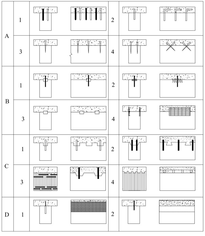 |
Fig. (1). Commonly used timber-concrete connections: (A-1) nails; (A-2) glued reinforced concrete steel bars; (a-3&4) screws; (B-1) split rings; (B-2) toothed plates; (B-3) steel tubes; (B-4) steel punched metal plates; (C-1) round indentations in timber, with fasteners preventing uplift; (C-2) square indentations, ditto; (C-3) cup indentation and prestressed steel bars; (C-4) nailed timber planks deck and steel shear plates slotted through the deeper planks; (D-1) steel lattice glued to timber; (D-2) steel plate glued to timber. Adapted from [5]. |
Despite group 'A' connectors are less rigid, they are inexpensive and easy to fix. Connectors in group ‘B’ are found to be better in terms of strength, stiffness, and ductility when compared to dowel-type connectors [11]. The plausible reason is that connections with tubular-type, particularly the rigid ring connectors, provide higher stiffness, strength, and also leads to shear failure of the timber beam. Generally, nails and screws lead to tensile failure of timber, while shear failure usually appears for a higher load level [11, 12].
Shear connectors in Group C (notch/shear key cut out in the timber and reinforced with screw or anchorages) are found to provide better composite action than those in group B, with higher strength and stiffness. The shear key transmits the shear force providing strong and stiff connections while the anchorage resists the vertical load component [11, 12]. Shear connectors in group D, by far, are known for their best performance in terms of strength and stiffness for TCC system. The design calculation can be easily done using the “transformed” section method that assumes plane sections remain plane after bending.
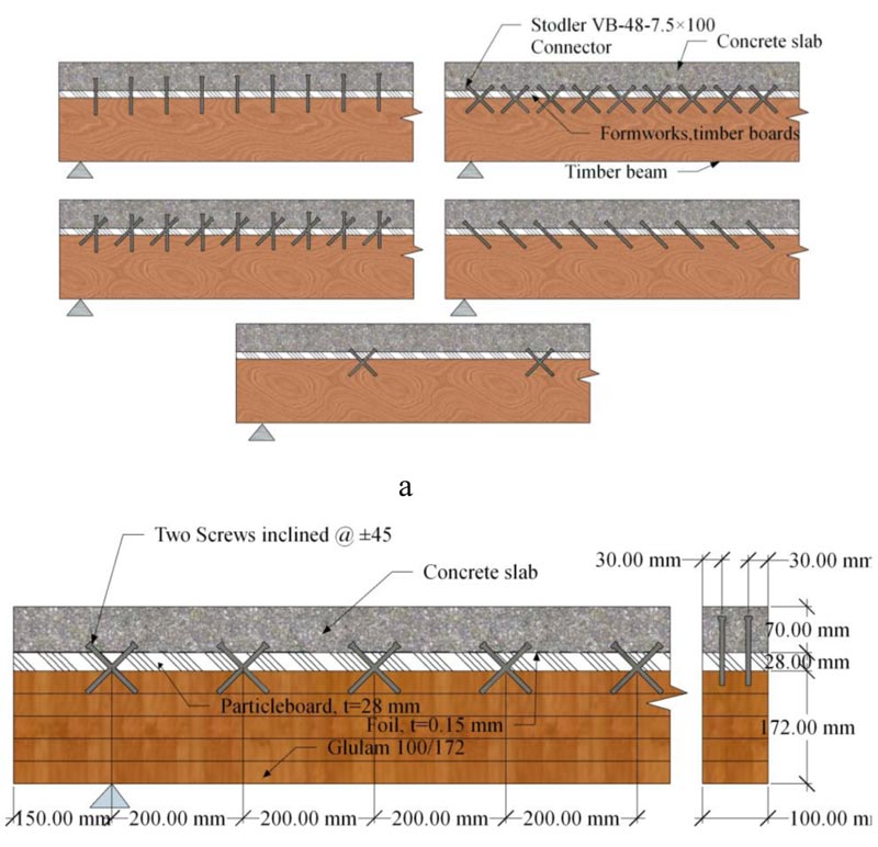 |
Fig. (2). Mechanical fasteners as shear connectors in a TCC system: a) picture adapted from [14]: b) picture adapted from [8]. |
This is because the interlayer slip between the concrete slab and the timber member is negligible. Therefore, either the concrete or the timber section can be changed to the other equivalent one with the same center of gravity. By contrast, connectors in groups A through C forms flexible connections with a relatively larger slip that cannot be disregarded, hence it requires a more complex design approach [5, 11, 12].
2.2.1. Mechanical Fasteners as Shear Connectors
Several studies have been conducted to study the mechanical performance of fasteners such as nails, screws, bolts, and horizontal shear connectors as a shear connector in TCC system. Ahmadi et al. [13] studied the behavior of TCC using high strength nails, screws, and bolts. The fastener length ranges from 100 mm to 150 mm. Fasteners were tested with static short and long-term bending by varying the embedment depth. It was recorded a twice higher ultimate load capacity and 80% reduced mid-span deflection than fully non-rigid connection. The behavior of the TCC system observed was within the acceptable practical limitations defined by building codes [13]. Meierhofer et al. [14] used screw connectors arranged at different orientations, both in straight and in a truss-like arrangement inclined at ±45o, as shown in Fig. (2a), and conducted several tests on the connectors and on the TCC system to evaluate the structural performances. The tests were short-term pullout tests on concrete, wood, and bending tests; and long-term shear and bending tests. The arrangement with the inclined orientation of screws in both directions shows better structural performance.
Van der Linden et al. [8] tested three categories of timber-concrete beams with different types of connections, of which one was screws installed at ±45Øas shown in Fig. (2b), with an interlayer of 28 mm of particleboard. The tests were shear, bending, and creep tests on composite beams; and Monte Carlo simulations of floor systems. They concluded that all connections used satisfied the requirements for serviceability and ultimate limit state.
Gelfi and Giuriani [15] conducted experimental research for stiffening and strengthening wooden floors. The local and global behavior of the composite was examined using stud connections from ordinary smooth steel bars pressed into predrilled holes in the timber beam without resins. In the study, two ways of connecting the concrete and the wood was adopted as shown in Fig. (3a): i) the concrete slab in direct contact with the wood beam using Ø12 mm stud connectors, and ii) interposed plank placed between the concrete slab and the timber beam with Ø16 mm stud is used to connect them. It is concluded that, apart from its simplicity during installations, the connection system has provided effective flexural stiffness and strength. They highlighted that the embedment depth of the stud greater than four-times its diameter does not significantly improve the connection stiffness and strength. Dias et al. [10] conducted a series of shear tests using dowel type of connecters obtained from smooth and profiled steel reinforcement bars. In the test, different types of timber were used: spruce, maritime pine, and chestnut; as well as different classes of concrete: low strength or lightweight, normal strength, and high strength concrete were used to manufacture the composite. Ceccotti et al. [16] conducted a comprehensive experimental investigation on 6 m TCC using glued-in Ø18 mm re-bar as a shear connector. The rebars are inserted into predrilled holes filled with epoxy-resins as shown in Fig. (3b). A preliminary short-term test was done before the long-term tests; the specimens were then subjected to a sustained load for 5 years in an outdoor condition. It was observed that the deflection markedly increased in the first two years, while the slip increased during the whole testing period. They concluded that composite beams in out-door conditions should be considered as 3rd service class according to Eurocode 5 [17].
Benitez et al. [18] experimentally investigated three different types of shear connectors for the design of new timber bridges and the rehabilitation of old bridges, aiming to provide a suitable and economical shear connector which does not require expensive or specialized equipment for the fixture. The connectors were positioned in such a way that it would maximize the degree of composite action. Static and dynamic responses were evaluated for connectors consisting of: i) 20 mm plain mild steel dowel inclined at 60Ø (Fig. 4a): ii) a circular hollow section (CHS) fitted in a groove of the same diameter in conjunction with 150 ×M16 coach screws (Fig. 4b): iii) and finally a universal column section (UC) fastened to timber using four 75 × M16 coach screw (Fig. 4c). They reported that high strength values can be achieved with both the UC and CHS + coach screw types, however, the UC type can provide full-composite action with far better ductility than the CHS + coach screw type. The UC and CHS + coach screw also sustained large forces after 100,000 cycles. He et al. [19] conducted push-out tests on bolted connections to experimentally and theoretically investigate TCC. Ø8 and Ø12 bolt with a length of 120 mm; and Ø16 bolt with a length of 100 mm and 120 mm were used as a shear connector. The result indicated that the mechanical behavior of such connection does not perform linearly even during the early stage of loading. Shear strength and slip modulus are found to be directly proportional to the diameter and square of the diameter, respectively.
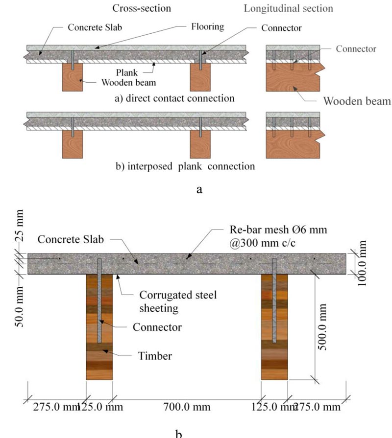 |
Fig. (3). Mechanical fasteners used as shear connector in a TCC system: a) Stud shear connectors for stiffening and strengthening wooden floors [15]: b) Shear connectors, picture adapted from [16]. |
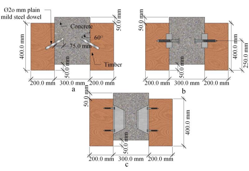 |
Fig. (4). Shear connectors for use in a composite system to construct new or rehabilitate old timber bridges: (a) 20 mm plain mild steel dowel inclined at 60o; (b) circular hollow section; (c) universal column section (adapted from [18]). |
Khorsandnia et al. [20] experimentally investigated strength and stiffness properties of LVL- concrete composite using shear connectors of Ø5 and 100 mm length normal wood screws, VB-4.8–7.5x165 SFS screws of Ø6 and 200 mm length inclined at 45°, and bird-mouth notch reinforced with Ø6 mm and length of 200 mm coach screw. Fig. (5) shows the screw type and connection details.
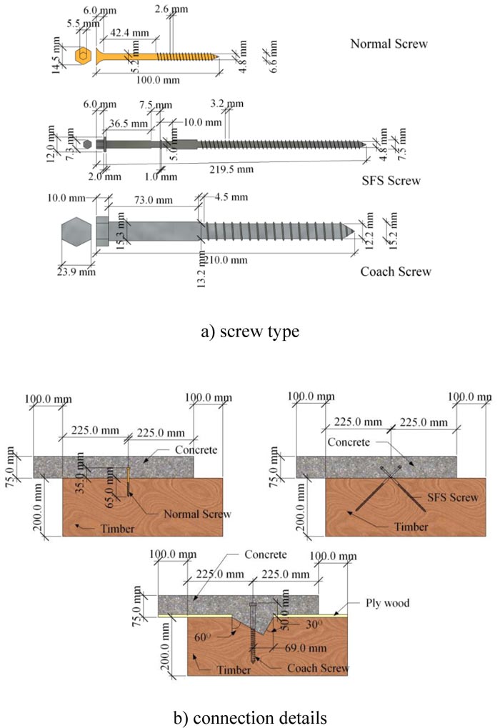 |
Fig. (5). Different types of screws used as a shear connector and connection details studied by [20]. |
2.2.2. Adhesives as Shear Connector
Adhesives have also been used as shear connectors. Brunner et al. [21] conducted bending test using adhesives bonded TCC. The specimens were prepared using adhesive-only to connect the timber beam and the concrete slab. In the test, a wet-to-wet process was adopted in which fresh concrete is poured onto epoxy-based adhesive while the adhesive being wet. This process is problematic because the fresh concrete may displace the wet adhesive. They reported that the test result had met the anticipations. Negrão et al. [22] tested cast-in-situ and prefabricated TCC beams using adhesives-only as a shear connector. The dowel-type connectors were also used for convenient comparisons. They found similarity in terms of strength; while those beams with adhesive-only showed higher stiffness thus less deflection. They also highlighted that the method can be used to both prefabrication and cast-in-situ (wet concrete) techniques of construction with a negligible difference. Eisenhut et al. [23] experimentally investigated the adhesive-bonded TCC system using epoxy resin-only. They reported that a rigid bond can be achieved at the interlayer in prefabricated TCC beams. However, it is also mentioned that the composite effect was adverse in terms of internal stress, temperature, and moisture.
2.2.3. Notched Connection
Van der Linden et al. [8] performed bending tests on composite specimens with notch connections reinforced with dowels and reported satisfactory structural performance of the composite. Gutkowski et al [24, 25]. tested the performance of notched connections in layered TCC floor systems. The notched shear key/anchor interlayer force transfer was reinforced with a steel dowel glued into a predrilled hole in the wood using an adhesive. The load-slip curve behaves predominantly linearly so that the initial tangent and secant approaches to determine the slip modulus did not apply to the anchored notch connection. It was observed that composite action that ranges from medium to high degrees was achieved. Fig. (6a,b) shows the connection details used in Van der Linden et al. [8] and Gutkowski et al [24, 25].
Fragiacomo et al. [26] experimentally studied the long-term behavior of the TCC system with a notched connection in which the specimens were monitored for 133 days under loading. Based on the experimental result, concrete with less shrinkage and camber on the wood deck is required to limit the deflection for serviceability inspection. Fig. (6b) shows the notch type used in the study.
 |
Fig. (6). Notch type shear connector in a TCC system: a) picture adapted from [24, 25]: b) picture adapted from [8]: c) picture adapted from [26]. |
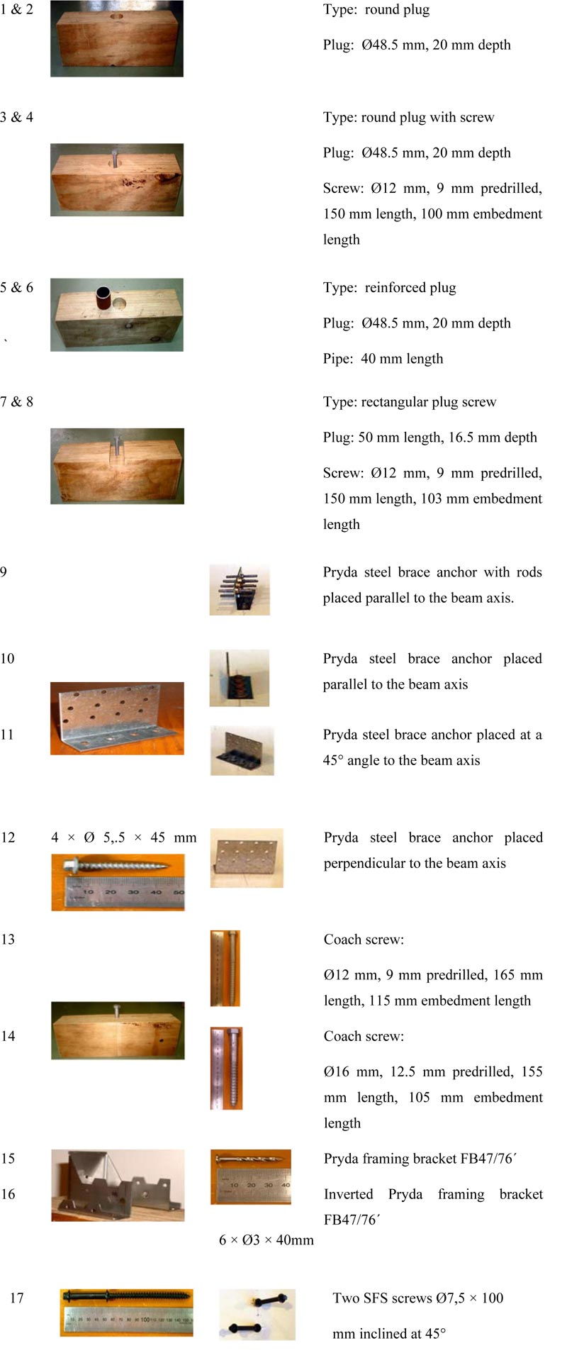 |
Fig. (7). TCC system made of the concrete slab and Laminated Veneer Lumber (LVL) using different shear connectors (picture taken from [27]). |
Deam et al. [27] conducted shear test on TCC system made of the concrete slab and laminated veneer lumber (LVL) using shear connectors that range from notch/plug to simple mechanical connectors as shown in Fig. (7). The study evaluated the strength, stiffness, and post-peak performance of the connectors. Concrete plugs reinforced with screw or steel pipe show high stiffness, strength, and post-peak behavior. The bearing area of the plugs has also influenced the strength and stiffness properties of the composite system. The rectangular plug provided better performance over a smaller round notch. Post-peak behavior could be improved by using larger diameter screws in larger notches. The shear test results were used to design an 8-meter span floor system. The rectangular concrete plug reinforced with a coach screw was shown to be capable of providing adequate composite action when installed equally spaced at 500 mm along the beam.
Yeoh et al. [7, 28, 29] conducted a study on the behavior of semi-prefabricated laminated veneer lumber (LVL)-concrete composite floor system aiming to develop a floor solution suitable for medium to large-span floors in multi-story timber buildings. Shear connectors are mainly composed of notch with rectangular and triangular shape reinforced with coach screw as shown in Fig. (8). In the study, the notch connector was adopted, varying the bearing area and the diameter of the reinforcing screw. It was found that the bearing area and shape of the notch significantly affect the strength and stiffness of the composite. The larger notch with a rectangular shape and larger reinforcing coach screw performed best in terms of strength and stiffness.
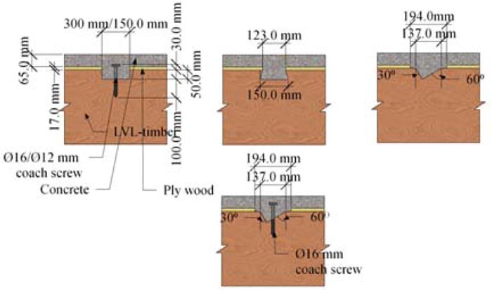 |
Fig. (8). Different types of notched connection in a TCC system (picture adapted from [7, 28, 29]). |
| Description | Picture | Description | Picture |
| SNP One 55 × 55 × 250 mm toothed metal plate, folded at an angle of 900, molded into the slab. |
 |
GSP One 115 mm wide folded steel plate, embedded into the slab for a depth of 50 mm and epoxy-glued into a 70 mm deep slot milled in the glulam beam. |
 |
| SM Continuous steel mesh embedded into the slab for a depth of 50 mm and epoxy-glued into a 50 mm deep slot milled in the glulam beam. |
 |
ST + S + N One Ø20 × 67 mm long steel tube inserted into the concrete slab with one Ø20 × 160 mm hexagon head coach screw and one notch cut from the glulam beam. |
 |
| SST + S One Ø20 × 47 mm long steel tube inserted into the concrete slab with one Ø20 × 120 mm hexagon head coach screw. |
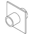 |
GDF One Ø20 × 120 mm dowel with flanges embedded into the concrete slab for a depth of 50 mm and epoxy-glued into a 70 mm deep hole drilled in the glulam beam. |
 |
| SP + N Two folded steel plates embedded into the slab for a depth of 50 mm and nailed to both sides of the glulam beam with 8 Ø4.5 × 75 mm annular ringed shank nails. |
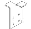 |
- | - |
Lukaszewska et al. [30, 31] evaluated the performance of seven different types of shear connectors in which three of them were newly developed for prefabricated TCC beams (see Fig. 9). The shear connectors were first embedded into a prefabricated concrete slab to enable “dry-dry” construction. The study indicated that it is possible to produce TCC structures as fully prefabricated elements, with concrete slabs manufactured off-site and assembled on-site on timber beams. Reduced construction cost, high speed of construction, and less effect of concrete shrinkage are the main aspects of the system compared to the cast-in-situ concrete. The authors concluded that relying on mechanical performance observed and simplicity of the applicability, SST + S and SP + N type connections were found to be the most favorable connectors for prefabricated timber–concrete composite systems, while some of the new shear connectors introduced (i.e. SST + S, SP + N, ST + S + N) as shown in Fig. (9) can acceptably perform and are comparatively cheap.
Djoubissie et al. [32] experimentally investigated the mechanical behavior of TCC system using threaded reinforcing bars as shear connectors, as shown in Fig. (10). Push-out tests conducted on rectangular and triangular-shaped notch reinforced with and without the threaded bars are also investigated and the performances of each tested shear connectors are then compared. It is reported that connections with screw and steel bar alone showed ductile behavior, while the notch showed brittle behavior. Moreover, connections with only steel bars showed the lowest stiffness.
Boccadoro et al. [33] conducted a bending test on a TCC system made of European beech (Fagus sylvatica) laminated veneer lumber (LVL) and concrete composite floor system using notch connection. It was seen that a design approach proposed by the author can be used to design beech LVL-concrete composite slabs with notched connections to guarantee a ductile failure mode and behavior that can easily be dealt with.
2.2.4. Metal Plate as Shear Connectors
Toratti and Kevarinmäki [34] designed two cast-in-situ and prefabricated TCC floor system using nail-plates as a shear connector. The floors were examined under vibrations and deflections due to walking and then loaded to failure. Van der Linden et al. [8] and Jorge et al. [35]. Yeoh et al. [7, 28, 29] have also studied composite system with toothed continuous steel mesh where they pointed out that such connectors had the advantage of labor cost-effective (Fig. 11).
Clouston et al. [12] used a new type of shear connector that is continuous steel mesh where half part is glued in a slot in the wood beam while the other half embedded in the concrete as shown in Fig. (12a). The composed system was tested for shear and bending. The experimental results showed that such connectors provide the highest strength, stiffness, and consistency, as well as the highest ductility. The bending test result also showed almost a fully-rigid composite action. Bathon et al. [36] studied the response of the WCC-building system constructed from fully prefabricated modular TCC under high wind speed up to 250 mph (400 km/h). The modular element usable in floors, walls, and roofs is a wood-concrete composite with a glued-in metal plate as a shear connector, as shown in Fig. (12b). It was found that, compared to contemporary timber or concrete buildings, the WCC-elements are more sustainable and economical.
| Type | Description | Type | Description |
 |
Rectangular notch with a length of 100 mm and a depth of 40 mm in the timber element |  |
Threaded steel connector (Ø12 mm) screwed at an angle to grain of 90Ø |
 |
Triangular notch with a depth of 40 mm in the timber element |  |
Triangular notch combined with a threaded steel connector (Ø12 mm) screwed at an angle to grain of 120Ø |
 |
Threaded steel connector (Ø10 mm) screwed at an angle to grain of 120Ø |  |
Triangular notch combined with a threaded steel connector (Ø12 mm) screwed at an angle to grain of 90Ø |
 |
Threaded steel connector (Ø12 mm) screwed at an angle to grain of 120Ø |  |
Lag screw of 10 mm diameter screwed at an angle to grain of 90Ø |
 |
Threaded steel connector (Ø10 mm) screwed at an angle to grain of 90Ø | - | - |
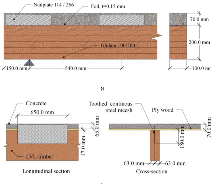 |
Fig. (11). Toothed continuous steel mesh used as a shear connector: a) picture adapted from [8]: b) picture adapted from [7, 28, 29]. |
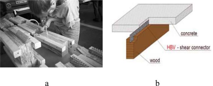 |
Fig. (12). Continuous steel mesh used as a shear connector: a) continuous steel mesh (Picture taken from [12]): b) glued-in metal plate [36]. |
Otero-Chans et al. [37] investigated the TCC system with a discrete connection using perforated steel plates glued in timber with epoxy adhesive. The connection system was also tested with reinforcing steel with different configurations (longitudinally and transversely), as shown in Fig. (13). The experimental results demonstrated that the TCC system with these connections is strong, stiff, and could bring to a ductile type of failure.
 |
Fig. (13). Glued-in perforated steel plates as shear connector (picture taken from [37]). |
2.2.5. Innovative Types of Shear Connectors Used in Composite System
Fragiacomo et al. [38] studied short and long-term behavior of TCC system using “Tecnaria” stud connector shown in Fig. (14a). In the tests, normal and light-weight concrete were used to manufacture the concrete slab. They performed short-term push-out, collapse, long-term collapse, and creep tests concluding that the connection provides substantial strength and stiffness. Fernandez-Cabo et al. [39] conducted a short-term shear test on timber–concrete composite using HSB© (Habitat System Beton) shear plate connector, which is manufactured using aluminum alloy (Fig. 14b), Ø6 mm and 160 mm long helicoidally threaded nail was used to preassemble the connectors, so the strength and stiffness capacity of the connector were determined. They concluded that provisions of Eurocode-5 (EC-5/1) for shear plate connectors are not directly applicable for the design of the HSB©.
Crocetti et al. [40] tested a new type of prefabricated TCC floor system made of fiber-reinforced concrete (FRC) and modified wood aiming to achieve good stiffness and a high degree of prefabrication. Shear anchor-keys of furfurylated wood and inclined steel tubes together with a screw were used as shear connectors in the investigation, as shown in Fig. (15). The result demonstrated that the anticipated connection systems showed reasonably high performance with a very high degree of composite action, even near failure load.
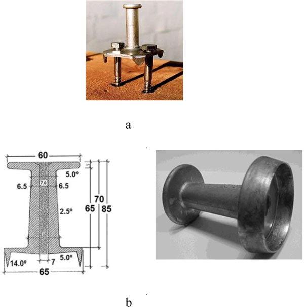 |
Fig. (14). Innovative types of shear connectors used in composite system: a) picture taken from [38]: b) picture taken from [39]. |
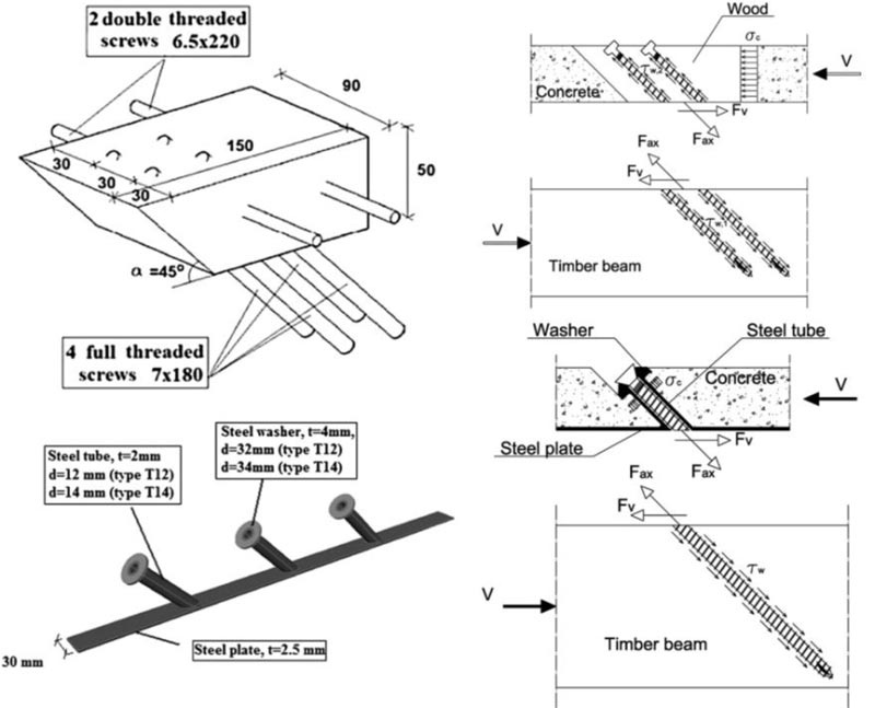 |
Fig. (15). Innovative types of shear connectors used in a TCC system: picture taken from [40]. |
Auclair et al. [41] introduced a new shear connector aiming to improve the ductility of a composite without a significant effect on the stiffness. The connector consists of a composite cylinder made of ultra-high performance fiber-reinforced concrete (UHPFRC) shell with a cylindrical steel core. Fig. (16) shows the composite connector used in Auclair et al. [41]. In the study, connection and composite systems were tested using push-out and bending tests, respectively. The result showed that the connection stiffness is mainly affected by the concrete shell diameter (Dc); while the steel cylinder, Ds, affects the strength, revealing an inverse relationship. Therefore, an optimized solution for the strength and stiffness property of the composite can be obtained by varying the diameter of the concrete shell and steel core.
2.3. Different Types of Timber Beams Used in TCC System
So far, different forms of timber have been used as a timber beam in the TCC system, aiming to enhance the timber beam performance in a composite system. Quang Mai et al. [42] conducted static and dynamic tests on five full-scale hybrids cross-laminated timber (CLT)–concrete composite floor. The cross-laminated timber (CLT) consists of five layers of laminate, 30mm each, making a total of 150 mm thickness CLT timber beam. Structural adhesives were used to bond each laminate, and also shear connectors of Ø10 mm coach screw and Ø7.5 mm SFS with a length of 180mm and 145mm, respectively, were used at different orientations (i.e. ± 45Ø and 90Ø). The result demonstrated that the CLT–concrete floor composite system had excellent structural performance in terms of strength capacity. Fig. (17a) shows the specimen tested details. Derikvand et al. [43] experimentally investigated the bending capacity of nail laminated timber concrete composite (NLTC) system made of nail laminated timber (NLT) and concrete Slab, as shown in Fig. (17b) under short term bending test using Ø7.4 mm and 145 mm long SFS screw inclined at 45Ø as shear connectors. The composite system demonstrated sufficient short-term bending performance to be used in the construction of higher-value structural floor products.
 |
Fig. (16). A new type of shear connector used in a TCC system (picture adapted from [41]). |
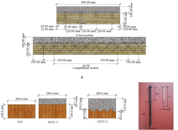 |
Fig. (17). a) CLT-concrete composite (picture adapted from [42]): b) NLT-concrete composite (picture adapted from [43]). |
2.4. Effect of Concrete Properties
The effect of concrete properties on the performances of TCC systems has been investigated by numerous researchers. Holschemacher et al. [44] conducted a push-out test using steel-fiber-reinforced concrete and timber composite using ordinary wood screws as shear connector aiming to rehabilitate an existing timber beam. With such concrete, a reduced slab thickness can be used with the required structural performance since steel fibers do not require concrete cover as compared to the conventional steel reinforcements for the potential upgrade of timber frame buildings, Koh et al. [45] conducted a push-out test on lightweight foamed concrete and Malaysian hardwood composite connected using different types of nails. They suggested higher grade light-weight concrete to fully exploit the efficiency of the connection. Grantham et al. [46] used light-weight concrete to form a TCC. An existing timber floor was upgraded to a TCC system using inclined SFS VB-48-7.5x100 mm as shear connectors and light-weight concrete incorporating recycled sewage sludge for the coarse aggregate. The system was subjected to a full-scale long-term and collapse test. The result demonstrated that the light-weight concrete revealed large shrinkage and creep, but favorable lower self-weight and high strength. Kieslich et al. [47] conducted bending tests on TCC system by combining innovative concrete properties for the concrete slab to experimentally investigate the influence of concrete properties on the stiffness of the composite. The combined concrete properties adopted were light-weight, self-compacting, and fiber reinforcements. These properties could help to minimize the dead load, cost related to compaction and reinforcing steel and to realize cost-effective and resource gentle TCC. Shariati et al. [48] conducted push-out tests on TCC with channel shear connector where the concrete slab is made of normal and light-weight aggregate concrete. It was found that the shear capacity of the composite with lightweight aggregate concrete is lower when compared to normal. Martins et al. [49] used (i) dowels, (ii) inclined cross screws and (iii) glued-in-bars as shear connectors to study the mechanical behavior of TCC system with a light-weight concrete slab made of partially replacing the cork with fine and coarse aggregates. The result highlighted that cork in concrete tends to decrease the mechanical behavior of the connection, which can be improved using connectors with a larger diameter.
Schanack et al. [50] conducted shear and bending tests to experimentally investigate the influence of concrete cracking on connector stiffness in TCC, using a half-inch diameter coach screw as shear connector. This study revealed that concrete cracking also results in a connector slip modulus reduction of up to 70%. FEM analysis also confirmed the same by giving safe predictions of the test result when the slip modulus is decreased by 60%, if concrete cracking is observed.
3. MECHANICAL PROPERTIES OF CONNECTORS
3.1. Bamboo-concrete Composite
Shan et al. [3] developed a new type of composite system called glubam-concrete composite or bamboo-concrete composite (BCC). The new composite system comprises bamboo beam replacing the timber joist of the conventional TCC. Shear connectors that are proven to provide a strong and stiff connection with high degree of composite action in a comparatively well-developed TCC, were utilized in the new composite system. Fiber structure, manufacturing process and mechanical performance of the glubam beam were also taken into account in the selection of shear connectors in the bamboo-concrete composite.
Glubam beam is used to manufacture the bamboo-concrete composite replacing the timber beam in the companion TCC. Glubam beam, an engineered bamboo, is made of laminating glubam sheets. Table 1 presents the mechanical properties of glubam used in the study. A glubam sheet is typically orthotropic material where fibers (bamboo strips) are arranged in the longitudinal and transverse directions with a ratio of 4:1. About 15 bamboo curtains (or less) of each 2 mm thick are used to manufacture glubam sheet. Each glubam sheet is then laminated one after the other to produce the glubam beam, until the required beam thickness is achieved. The mechanical properties of this product are quite reasonable for structural application with comparable or better performance as compared to other glue-laminated bamboo products or timber. So far, glubam has been used as a structural element in many structural applications, such as constructing buildings and bridge structures [3, 51]. The concrete for the flange in the BCC system is made of standard concrete with cubic compressive strength of 36.0 MPa.
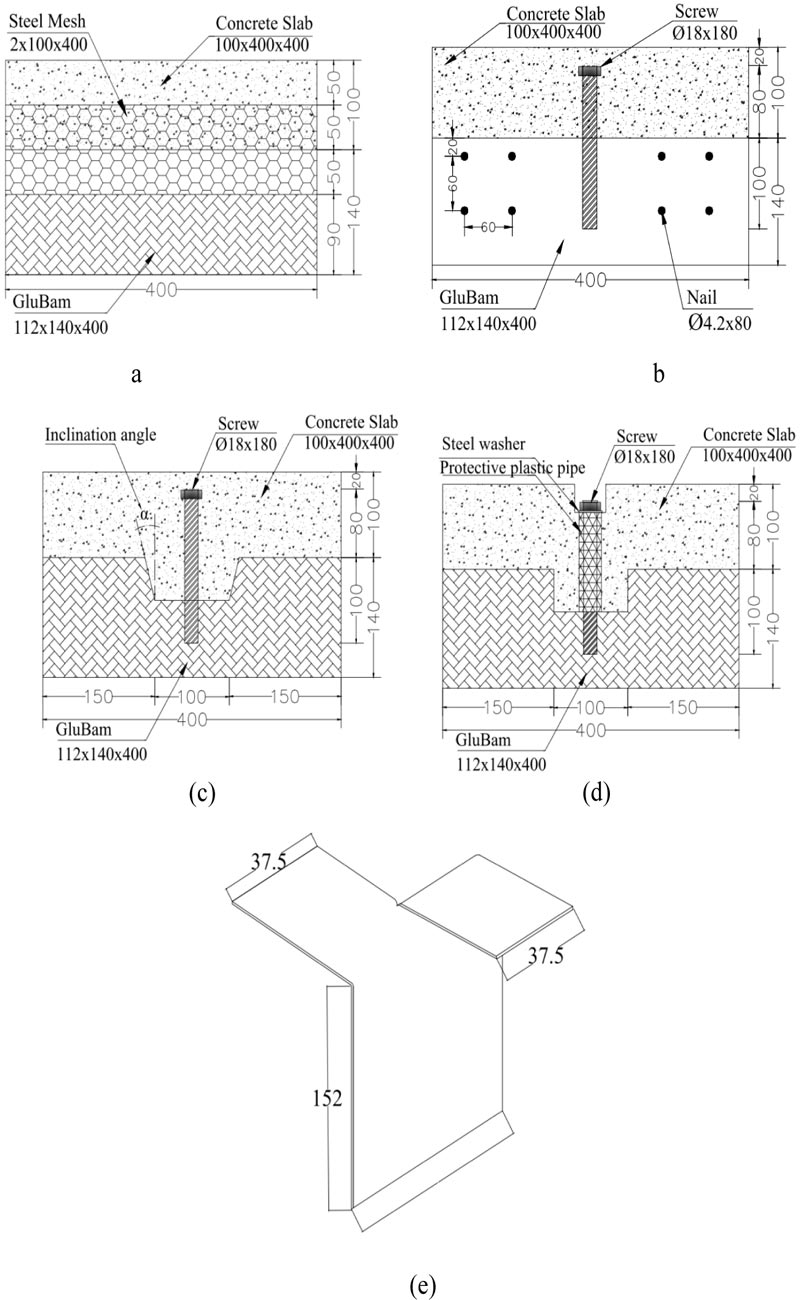
Shan et al. [3] selected continuous steel mesh (SM), notched connector (NC), screw connector (SC), and steel plate (SP) and pre-tightening notched connector (PNC) as shear connector in the new composite. All the connectors were glued in, using structural two-component epoxy adhesive. The steel mesh used was 2 mm x 400 mm (thickness x length). Connections details used in [3] are shown in Fig. (18).
| In-plane Longitudinal Compressive Strength (MPa) | Perpendicular to Plane Compressive Strength (MPa) | In-plane Longitudinal Tensile Strength (MPa) | Bending Strength (MPa) | Density (kg=m3) | Elastic Modulus (MPa) |
|---|---|---|---|---|---|
| 54 | 68 | 80 | 94 | 880 | 9,400 |
3.2. Timber-concrete Composite
Numerous researches have been conducted to study the mechanical properties of connections in TCC using various types of shear connectors. Among these TCC systems, some recent ones are considered herein to compare the local and global failure behavior. For convenient comparison, studies are selected based on the type of shear connectors used. Therefore, test results of TCC having similar connection types to that of the bamboo-concrete composites are considered. It is eminent to contemplate here that though the selected TCCs are with similar connection type to the bamboo-concrete composite, it does not necessarily mean that these connectors are identical (i.e., the shear connectors are similar, however, some of the connector’s features such as: diameter, length and installation orientation of screws; length and depth of the notch, and properties related to the size of shear connectors used in the bamboo-concrete composite -might not necessarily be the same and equal to those used in the TCC system). Nevertheless, these dissimilarities are not that significant to affect the comparative, since the impact of each characteristic of shear connectors on the composite performance, can be addressed through the studies done to identify how such parameters affect the performances of composites. It should also be noted that specimens chosen herein for comparison may not necessarily have the same or similar cross-sectional property (shape and size), some are rectangular while others are T-shape. Thus, this comparison might not be exhaustive in terms of performance, but it is supposed to provide a comparative-based knowledge of the mechanical and structural performances of this new type of composite with BCC, as parallel to those studies on the TCC system.
Accordingly, TCC systems investigated by Gutkowski et al. [25], Clouston et al. [52], Deam et al. [27], Yeoh et al. [29], Lukaszewska et al. [30], Khorsandnia et al. [20] and Djoubissie et al. [32] are considered herein for the comparison of mechanical properties of the connection.
3.3. Specimen Details of BCC and TCC
Table 2 reports the connection type, component size of the specimens (size of timber/bamboo beam and the concrete slab) that forms cross-sectional details of the composite, and material properties of test specimens in each study. For the notch connection (NC), for instance, 50d x 150l NC-15-Ø16 denotes notch connection with notch depth, d=50mm, notch length, l=150mm, angle of inclination of the notch cut of 150 and screw/dowel of diameter 16 mm that is used along with the notch to reinforce the notch connection. Lukaszewska et al. [30] used a coach screw of Ø 20 ×160 mm (analogous to diameter × length) inserted into Ø20 × 67 mm steel tube along with the notch to connect the concrete slab and the timber beam in which the steel tube is totally inserted in the concrete slab.
For the screw connection (SC), Deam et al. [27] used coach screws of Ø12 ×165 mm and Ø16 ×155 mm (analogous to diameter × length) with embedment lengths of 115 mm and 105 mm, respectively, and two SFS screws Ø7.5 × 100 mm inclined at ±45Ø. Lukaszewska et al. [30] used a hexagon head coach screw of Ø20 ×120 mm along with an Ø20 ×47 mm steel tube that is inserted into the concrete. The steel tube is totally embedded in the concrete, while the connection between the concrete and the timber beam is maintained by the coach screw. Khorsandnia et al. [20] used a normal wood screw of Ø5 × 100 mm with an embedment length of 65 mm and SFS screw of series is VB-4.8–7.5x165 with Ø6 × 200 mm installed inclined at ± 45Ø. Lag screw of Ø10 × 152 mm with embedment length of 115 mm is among shear connectors used in Djoubissie et al.’s [28] study.
| Author | Connector Type | Connector Description | Timber | Concrete |
L [mm] |
||||
|---|---|---|---|---|---|---|---|---|---|
|
t [mm] |
h [mm] |
Et [MPa] | w [mm] |
d [mm] |
fc [MPa] | ||||
| Gutkowski et al. [25] | NC | 25d x102l NC-15-Ø12 | 38.00 | 89.00 | 1250.00 | 38.00 | 64.00 | 24.00 | 305.00 |
| NC | 31d x127l NC-15-Ø12 | 38.00 | 89.00 | 1250.00 | 38.00 | 64.00 | 24.00 | 305.00 | |
| NC | 38d x152l NC-15-Ø12 | 38.00 | 89.00 | 1250.00 | 38.00 | 64.00 | 24.00 | 305.00 | |
| NC | 25d x102l NC-15-Ø12 | 86.00 | 89.00 | 1210.00 | 89.00 | 64.00 | 24.00 | 305.00 | |
| NC | 31d x127l NC-15-Ø12 | 86.00 | 89.00 | 1210.00 | 89.00 | 64.00 | 24.00 | 305.00 | |
| NC | 38d x152l NC-15-Ø12 | 86.00 | 89.00 | 1210.00 | 89.00 | 64.00 | 24.00 | 305.00 | |
| Clouston et al. [52] | SM | SM | 80.00 | 140.00 | 11500.00 | 400.00 | 80.00 | 55.00 | 400.00 |
| Dean et al. [27] | NC | 16.5d x50l NC-0-Ø12 | 105.00 | 138.00 | 13200.00 | 360.00 | 70.00 | 30.40 | 433.00 |
| NC | 16.5d x50l NC-0-Ø12 | 105.00 | 138.00 | 13200.00 | 360.00 | 70.00 | 30.40 | 433.00 | |
| SC | Ø16 screw | 105.00 | 138.00 | 13200.00 | 360.00 | 70.00 | 30.40 | 433.00 | |
| SC | Ø12 screw | 105.00 | 138.00 | 13200.00 | 360.00 | 70.00 | 30.40 | 433.00 | |
| Yeoh et al. [29] | NC | 50d x150l NC-00-Ø16 | 63.00 | 400.00 | 11300.00 | 400.00 | 65.00 | 30.00 | 750.00 |
| NC | 50d x50l NC-00-Ø16 | 63.00 | 400.00 | 11300.00 | 400.00 | 65.00 | 30.00 | 750.00 | |
| NC | 25d x150l NC-00-Ø16 | 63.00 | 400.00 | 11300.00 | 400.00 | 65.00 | 30.00 | 750.00 | |
| NC | 50d x150l NC-00- Ø00 | 63.00 | 400.00 | 11300.00 | 400.00 | 65.00 | 30.00 | 750.00 | |
| NC | 50d x50l NC-00-Ø12 | 63.00 | 400.00 | 11300.00 | 400.00 | 65.00 | 30.00 | 750.00 | |
| NC | 50d x150l NC-00-Ø16 | 63.00 | 400.00 | 11300.00 | 400.00 | 65.00 | 30.00 | 750.00 | |
| Lukaszewska et al. [30] | SM | SM | 115.00 | 135.00 | 10700.00 | 400.00 | 60.00 | 25.00 | 400.00 |
| SC | SST + S Ø20 | 115.00 | 135.00 | 10700.00 | 400.00 | 60.00 | 25.00 | 400.00 | |
| SP | SP + N | 115.00 | 135.00 | 10700.00 | 400.00 | 60.00 | 25.00 | 400.00 | |
| SP | GSP | 115.00 | 135.00 | 10700.00 | 400.00 | 60.00 | 25.00 | 400.00 | |
| NC | ST + S + 25d x 100l NC-15- Ø20 | 115.00 | 135.00 | 10700.00 | 400.00 | 60.00 | 25.00 | 400.00 | |
| Khorsandnia et al. [20] | SC | Ø5 Normal screw | 45.00 | 200.00 | 11300.00 | 300.00 | 75.00 | 36.60 | 550.00 |
| SC | Ø6 SFS-± 45Ø | 45.00 | 200.00 | 11300.00 | 300.00 | 75.00 | 36.60 | 550.00 | |
| NC | BM NØ16 | 45.00 | 200.00 | 11300.00 | 300.00 | 65.00 | 36.60 | 550.00 | |
| Djoubissie et al. [32] | SC | Ø10 screw | 65.00 | 160.00 | 12155.00 | 300.00 | 50.00 | 25.10 | 350.00 |
| Shan et al. [3] | NC | 50d x100l NC-0-Ø18 | 112.00 | 140.00 | 9400.00 | 400.00 | 100.00 | 36.00 | 400.00 |
| NC | 50d x100l NC-15-Ø18 | 112.00 | 140.00 | 9400.00 | 400.00 | 100.00 | 36.00 | 400.00 | |
| SC | Ø18*180 screw | 112.00 | 140.00 | 9400.00 | 400.00 | 100.00 | 36.00 | 400.00 | |
| SM | SM | 112.00 | 140.00 | 9400.00 | 400.00 | 100.00 | 36.00 | 400.00 | |
| SP | SP | 112.00 | 140.00 | 9400.00 | 400.00 | 100.00 | 36.00 | 400.00 | |
| PNC | 25d x102l NCØ13 | 112.00 | 140.00 | 9400.00 | 400.00 | 100.00 | 36.00 | 400.00 | |
The continuous steel mesh (SM) used in Shan et al.’s [47] study is a similar type to that used by Clouston et al. [52] and Lukaszewska et al. [30] in terms of size and the way it is installed in the concrete slab and timber beam (embedment depth into the glubam/timber beam and the concrete slab).
The folded steel plate (SP) used in Lukaszewska et al.’s [26] study is 115 mm wide, connecting the timber and concrete with an embedment depth of 50 mm and 70 mm in the concrete slab and glulam beam, respectively. The folded steel plate used in the BCC system has a width of 75 mm while the embedment depth being the same as the TCC.
3.4. Shear Tests
The performance of the connection in both composites (BCC and TCC) is assessed through push-out tests to evaluate the strength and stiffness properties. The load-slip curve is, therefore, an essential output of the test to evaluate the connection strength and stiffness. Different test set-up could be used to perform the push-out test, as the asymmetrical or one side push-out test and the symmetrical push-out test. In the symmetrical test, the timber beam is connected to two concrete slabs in an ‘H’ shape. The asymmetrical test (one side push-out test), may overestimate connection strength and stiffness when compared to the symmetrical push-out test, due to the intrinsic eccentricity in the asymmetrical test configuration. This creates a force-couple that enhances the mechanical properties of the connection due to the friction [30].
Strength and stiffness resulting from the push-out test are used to design connections in a composite system at serviceability (SLS) and ultimate (ULS) limit states. The connection secant slip modulus of K0.4, K0.6 and K0.8 determined at 40%, 60% and 80% of the estimated maximum shear force are used to estimate the average collapse strength for verification of the serviceability and ultimate limit state in the design of composites, respectively. Therefore, a proper understanding of the overall load-slip behavior and the failure phenomenon of the push-out test is very crucial to understand the structural behavior in a composite system under loading. In the following, the failure mode, maximum shear strength and the stiffness of the BCC system, are compared to the above-mentioned companion TCCs. In all studies mentioned herein, the maximum shear force (Fmax) is considered as the peak load applied during the test or the load corresponding to a relative slip of 15 mm.
3.4.1. Comparison of Failure Modes and Force-slip Behavior
Many researchers demonstrated that the load-slip response of composite connections is pronounced nonlinear. The extent of nonlinearity and the overall behavior vary depending on the connection type used, and at the same time, it depends on the material properties of each component of the composed system. Dias et al. [10] presented a typical load-slip curve for various types of connection for the TCC system. It can be seen from Fig. (18) that the most nonlinear behavior is revealed in the dowel type fasteners (mechanical fasteners including screws, bolts, steel bars, etc.) while the glued type connection exhibits less non-linear behaviors. Such nonlinear behavior also appeared to be a typical behavior in the load-slip curves to all connections used in the BCC system studded by Shan et al. [3].
Shan et al. [3] mentioned that in the BCC system with screw shear connector a typical elasto-plastic load-slip behavior, characterized by a large plastic phase after a certain slip value, was observed. This is certainly a typical load-slip behavior of a TCC system with dowel type of connection, as shown in Fig. (19). GluBam beam cracking at slip value of 15 mm, and a formation of plastic hinge on the screw at failure of the specimen is also noticed. Fig. (20) shows the final failure of the specimens in each study (picture taken from the respective literature). Deam et al. [27] reported the formation of a plastic hinge in both screws (i.e. Ø12 and Ø16). For specimens with larger screw diameter, it is mentioned that the LVL beam split in the left and right side of the screw in the longitudinal direction. Lukaszewska et al. [30] reported only the formation of the plastic hinge on the screw with no observable damage in both the LVL beam and concrete slab. The failure of the TCC reported in Khorsandnia et al. [20] can be generally attributed to the failure of both the connector and crushing of LVL beam. For the SFS screw, the failure is similar to the one reported in other studies, where fracture of the LVL being the reason for the global failure with the formation of plastic hinge on the screw. For the normal screw, the connection system appears to be poor in terms of strength, and the global failure of the composite is particularly attributed to the local failure of the connection following the fracture of LVL beam.
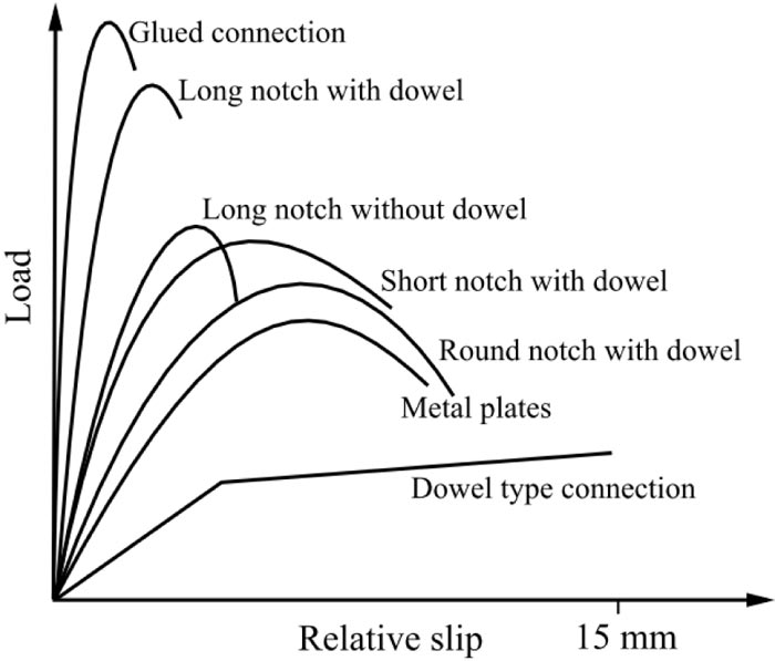 |
Fig. (19). Typical load slip behavior of connection system (adapted from Dias et al. [10] and Yeoh et al. [6]). |
 |
Fig. (20). Failure mode of screw connection system. |
In a well-designed composite system, local failure in the connection system is less probable since the connection is designed in such a way that it is stiff and strong enough to resist the required load. In such a case, the main concern will be the material characteristics in terms of load-bearing capacity and extent of damages. As can be seen from Fig. (20) below, the failure reported in all studies of the TCC system, but Lukaszewska et al. [30], is mainly attributed to the failure of the LVL joist, and similarly, failure of the glubam for the BCC system. It is noteworthy to consider that, apart from the material type used, the stiffness and strength property of a composite system, with screw connection, vary depending on various factors such as the screw diameter, screw orientation and the embedment depth. In almost all the above-mentioned studies of the composite system, the concrete fracture contribution to the global failure is found to be insignificant, however, Lukaszewska et al. [30] reported concrete slab failure as the primary reason for the global failure of composite system. The concrete slab mentioned in the study of Lukaszewska et al. [30] is prefabricated concrete with a strength class of C-20/25, which is lower strength grade when compared to other studies reported herein (Table 2).
For the composite system with notch shear connector, the formation of an inclined crack of concrete inside the notch and delamination cracking of glubam sheet, under partial compression at the base of the notch, was identified as the main reason for the global failure of composite specimens in all the BCC system regardless of the angle of inclination of the notch cut, and post-tensioning of the reinforcing coach screw. For the TCC system, Lukaszewska et al. [30] reported concrete fracture in the notch as a result of the combination of shear at the base of the notch and tension at the interface of the timber beam and the concrete slab. This is attributed to the strut and tie mechanism in the notch due to the eccentric bearing force at the timber-to-concrete interface [30]. LVL beam cracking along the plane that extends from the base of the notch is also revealed. A similar failure phenomenon was described by Yeoh et al. [29] and Gutkowski et al. [25] for such connection, particularly for rectangular notches. Fig. (21) illustrate concrete damage inside the notch and the global failure phenomenon of specimens with the notch connection for the BCC and TCC system as reported in the literature. It can be seen that the concrete damage in the notch is essentially similar. However, the inclined crack is slightly larger for the BCC, while the overall concrete fracture is larger in the TCC system. The damage extent in the LVL and glubam beams (cracking at the base of the notch) as well is somehow different.
Fig. (22) illustrates the failure mode with continuous steel mesh connector (SM) type of shear connector in BCC and TCC system. As reported in cited litratures and seen in the Figure, the failure phenomenon is observed to be different in all cases. In the BCC system, it is reported that the composite specimens exhibited linear behavior up to half the peak load. The failure is particularly attributed to the splitting of the glubam due to the delamination cracking of the glubam longitudinally along the punching direction of the steel mesh connector. In the TCC system, Lukaszewska et al. [30] explained that linearity was revealed almost till the peak load. The failure was mainly due to the brittle failure of concrete followed by the yielding and tearing of the steel mesh. On the other hand, Clouston et al. [52] stated that the failure is exclusively attributable to the yielding and then rupture of the steel mesh, with no noticeable failure in both the concrete slab and timber beam.
As stated earlier, the primary objective of this study is to characterize the mechanical and structural behavior of glubam-concrete as compared to the TCC, though not robust. Therefore, the interest herein essentially lies in identifying the basic feature of the global and local failure phenomenon of these composites in which basic differences are supposed to be highlighted in terms of the connector, concrete and the glubam/timber beam. To this end, it is apparent that the failure phenomenon of glubam-concrete composite with the continuous steel mesh shear connector appears to be poles apart from that observed in the timber-concert composite. Therefore, the difference in the failure phenomenon of the two composite systems, as far as the continuous steel mesh connector is concerned, can be concluded: i) In the BCC system, the delamination cracking of the glubam beam is somehow pronounced in the punching direction longitudinally. By contrast, no damage is reported in the LVL beam of the TCC system. This could probably be due to the glubam used in the BCC system having weak delamination cracking resistance capacity. This property is related to the adhesion capacity of the adhesive used to manufacture the glubam and can be improved by applying structural adhesives which could give better adhesion in laminating the glubam sheet. The failure of the shear connector was the reason for the global failure of the TCC system reported in Clouston et al. [52], while the concrete failure followed by the rapture of the connector is the reason for the failure in Lukaszewska et al. [30]. It is recalled that the concrete strength class is comparatively lower [30].
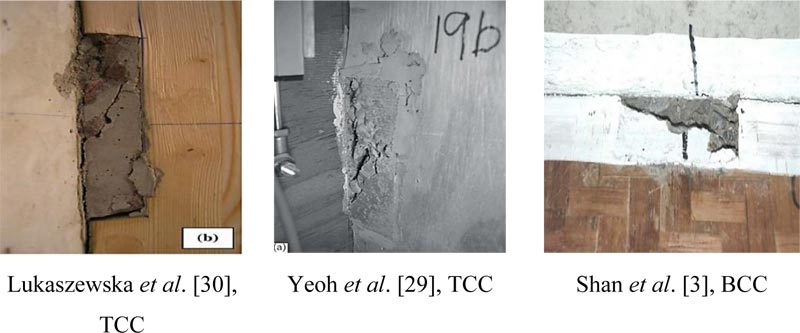 |
Fig. (21). Failure mode of Notch connection. |
 |
Fig. (22). Failure mode of continuous steel mesh connection. |
The other type of shear connector used in the BCC system is a folded Steel Plate (SP). This connection in the glubam-concrete composite revealed an elasto-plastic behavior. Near the peak load, the connector slightly rotated as a result of the local compression failure of the glubam beam. The delamination cracking and splitting of the glubam beam in the longitudinal direction was observed and identified as the reason for the global failure of the composite. A similar rotation phenomenon of the connector is also reported in Lukaszewska et al. [30] for the TCC system where the connector rotated leading to cracking of the concrete slab.
Fig. (23) shows the failure mode of specimens with folded steel plate types of shear connectors in both the TCC and BCC system. As can be seen in Fig. (23), in the glubam-concrete composite, the failure, once again, is primarily attributed to the delamination cracking of the glubam beam. Yet, the concrete slab cracking is seen to be comparatively higher for this type of connection than composites with other types of connection in the BCC system. Conversely, it is reported that the concrete fracture is the main reason for the failure of the TCC system in Lukaszewska et al. [30]. Once again recalling that in this study fracture of concrete slab has been reported as the prime cause for the failure of the composite system in all connection types used.
3.4.2. Comparison of Shear Capacity and Stiffness
Fig. (24) presents the normalized shear strength comparison of the BCC and the TCC system. In this comparison, the shear strength (Fmax) of each composite is divided by the corresponding total cross-sectional area (the sum of the cross-sectional area of concrete and timber/glubam). Then this distributed pressure over the cross-section is normalized. For this purpose, the ratio of the area of the glubam/timber to the total area of the corresponding composites is determined. Then the ratio of cross-sectional area of glubam beam of the BCC (the ratio of the cross-sectional area the glubam beam to the total cross-sectional area of the glubam-concrete composite) is taken as a reference to determine the relative equivalent area of the timber in the TCC. In this way, a relative value of the timber cross-section to the glubam cross-section is determined. This value is used to determine the normalized shear strength by dividing the distributed shear force by this value. This is an effort to minimize the strength capacity difference due to the size effect of the specimen. Therefore, it could give the load-carrying capacity of the glubam to the equivalent area of the timber beam. The difference, therefore, somehow will be mainly attributed to the material property.
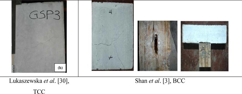 |
Fig. (23). Failure mode of folded metal plate connection. |
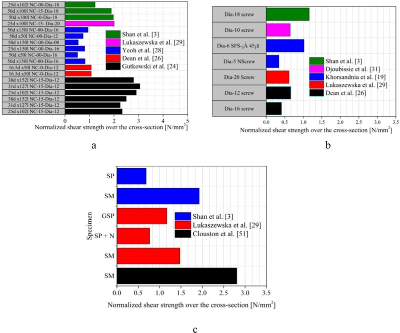 |
Fig. (24). Normalized shear strength on the face of the cross-section: a) Notched connection: b) Screw connection: c) Steel Plate connection (SP) and continuous steel mesh connection (SM). |
Table 3 presents stiffness, the maximum shear capacity, the computed cross-sectional properties and the normalized shear capacity of the BCC and TCC system. As can be seen from the Table 3, the continuous steel mesh and the notch series exhibited the higher stiffness in both the timber–concrete and glubam-concrete composite. For the TCC system, the continuous steel mesh connector exhibited the highest stiffness value, while the notch exhibited the highest in the BCC system. Likewise, the steel plate connection exhibits the lowest stiffness in the glubam-concrete composite, while the screw shows the lowest stiffness in the TCC.
Fig. (24) shows that the continuous steel mesh and notch connections showed the highest shear resistance in the timber-concrete and glubam-concrete composites. While the screw and the steel plate connection showed the least strength. However, there are some differences in the connection behavior among these two composites, for instance, the strength capacity of the continuous steel mesh for TCC system reported in Lukaszewska et al. [30] indicates 27% lower shear resistance than the notch connection, while it appeared that both connections exhibit almost equal strength capacity in the glubam-concrete composite except for the pre-tightened notch connection. The screw connection revealed the lowest strength capacity in the TCC system, whereas the steel plate connection being the lowest in the BCC. The comparatively lower stiffness and strength values of the continuous steel mesh and steel plate in the BCC than the TCC system could be due to the lower delamination cracking resistance of the glubam beam along with the nature of such connectors, and how these connectors are installed potentially triggers delamination cracking of the glubam beam.
As can be seen in Fig. (24) and Table 3, it can be generalized that the strength and stiffness properties of the glubam-concrete composite are either or even better than the TCC. It is noteworthy to consider that some aspects of the connector could be attributed to the shear strength capacity variation of the composite; for instance, a composite with larger notch length, larger screw diameter, or larger embedment depth of screw, will have higher shear strength and better stiffness even within the same type of composite system.
3.4.3. Comparison of Stiffness Degradation
As mentioned earlier, secant slip modulus K0.4, K0.6 and K0.8 refer to stiffness at serviceability, ultimate and near collapse loads, respectively. These values are mainly used to determine the load-carrying capacity of the composite in the design of the composite structure at the corresponding limit states. Fig. (25) illustrates the stiffness degradation of the BCC and TCC system for the connection used in the composites. In the Figure, the secant slip modulus at the ultimate and near collapse load are presented relative to the secant slip modulus at the serviceability limit state. The degradation level indicates the extent of stability of the stiffness of the composite system until the failure of the composite. This shows how the connection system in the composite loses its stiffness upon increasing the load. As can be seen in Fig. (25), the stability varies for various connections, however, it is noticeable that generally, the BCC has better stability in terms of stiffness degradation when compared to the TCC.
| Author | Connection Type | Shear Connector Description | K0.4 [KN/mm] | K0.6 [KN/mm] | K0.8 [KN/mm] | Fmax [KN] |
At [mm2] |
Ac [mm2] |
Asum [mm2] |
F/Asum [KN/mm2] |
Nt or Nb |
Nr = Nt/Nb | Normalized Shear Capacity [N/mm2] |
|---|---|---|---|---|---|---|---|---|---|---|---|---|---|
| a | b | c | d=b + c |
e= f / d |
f = b / d |
g |
h= e / g |
||||||
| Gutkowski et al. [25] | NC | 25d x102l NC-15-Ø12 | N/A | 21.10 | N/A | 84.00 | 10146.00 | 7296.00 | 17442.00 | 4.82 | 0.58 | 2.07 | 2.33 |
| NC | 31d x127l NC-15-Ø12 | N/A | 27.80 | N/A | 81.00 | 10146.00 | 7296.00 | 17442.00 | 4.64 | 0.58 | 2.07 | 2.25 | |
| NC | 38d x152l NC-15-Ø12 | N/A | 28.20 | N/A | 90.00 | 10146.00 | 7296.00 | 17442.00 | 5.16 | 0.58 | 2.07 | 2.50 | |
| NC | 25d x102l NC-15-Ø12 | N/A | 20.30 | N/A | 79.00 | 7654.00 | 5696.00 | 13350.00 | 5.92 | 0.57 | 2.04 | 2.91 | |
| NC | 31d x127l NC-15-Ø12 | N/A | 24.60 | N/A | 83.00 | 7654.00 | 5696.00 | 13350.00 | 6.22 | 0.57 | 2.04 | 3.05 | |
| NC | 38d x152l NC-15-Ø12 | N/A | 21.80 | N/A | 76.00 | 7654.00 | 5696.00 | 13350.00 | 5.69 | 0.57 | 2.04 | 2.80 | |
| Clouston et al. [52] | SM | SM | N/A | 415.46 | N/A | 111.62 | 11200.00 | 32000.00 | 43200.00 | 2.58 | 0.26 | 0.92 | 2.81 |
| Dean et al. [27] | NC | 16.5d x50l NC-0-Ø12 | 297.00 | 197.30 | 148.50 | 54.90 | 14490.00 | 25200.00 | 39690.00 | 1.38 | 0.37 | 1.30 | 1.07 |
| NC | 16.5d x50l NC-0-Ø12 | 297.00 | 197.30 | 148.50 | 54.90 | 14490.00 | 25200.00 | 39690.00 | 1.38 | 0.37 | 1.30 | 1.07 | |
| SC | Ø16 screw | 195.50 | 2.90 | 1.70 | 21.50 | 14490.00 | 25200.00 | 39690.00 | 0.54 | 0.37 | 1.30 | 0.42 | |
| SC | Ø12 screw | 88.30 | 21.40 | 2.70 | 34.20 | 14490.00 | 25200.00 | 39690.00 | 0.86 | 0.37 | 1.30 | 0.66 | |
| Yeoh et al. [29] | NC | 50d x150l NC-00-Ø16 | 80.20 | 75.40 | 61.70 | 73.00 | 25200.00 | 78000.00 | 103200.00 | 0.71 | 0.24 | 0.87 | 0.82 |
| NC | 50d x50l NC-00-Ø16 | 38.20 | 34.50 | 27.50 | 46.00 | 25200.00 | 78000.00 | 103200.00 | 0.45 | 0.24 | 0.87 | 0.51 | |
| NC | 25d x150l NC-00-Ø16 | 112.80 | 102.20 | 76.10 | 71.80 | 25200.00 | 78000.00 | 103200.00 | 0.70 | 0.24 | 0.87 | 0.80 | |
| NC | 50d x150l NC-00- Ø00 | 104.70 | 59.30 | 41.30 | 48.30 | 25200.00 | 78000.00 | 103200.00 | 0.47 | 0.24 | 0.87 | 0.54 | |
| NC | 50d x50l NC-00-Ø12 | 77.90 | 74.50 | 62.30 | 66.00 | 25200.00 | 78000.00 | 103200.00 | 0.64 | 0.24 | 0.87 | 0.74 | |
| NC | 50d x150l NC-00-Ø16 | 211.20 | 145.00 | 95.50 | 84.20 | 25200.00 | 78000.00 | 103200.00 | 0.82 | 0.24 | 0.87 | 0.94 | |
| Lukaszewska et al. [30] | SM | SM | 483.8 | 449.4 | 396.0 | 81.20 | 15525.00 | 24000.00 | 39525.00 | 2.05 | 0.39 | 1.39 | 1.47 |
| SC | SST + S Ø20 | 5.90 | 6.80 | 6.40 | 33.90 | 15525.00 | 24000.00 | 39525.00 | 0.86 | 0.39 | 1.39 | 0.61 | |
| SP | SP + N | 258.80 | 113.10 | 68.30 | 42.30 | 15525.00 | 24000.00 | 39525.00 | 1.07 | 0.39 | 1.39 | 0.77 | |
| SP | GSP | 248.50 | 183.40 | 130.90 | 64.40 | 15525.00 | 24000.00 | 39525.00 | 1.63 | 0.39 | 1.39 | 1.17 | |
| NC | 25d x 100l NC-15-Ø20 | 235.70 | 234.40 | 178.00 | 110.60 | 15525.00 | 24000.00 | 39525.00 | 2.80 | 0.39 | 1.39 | 2.01 | |
| Khorsandnia et al. [20] | SC | Ø5 Normal screw | 45.00 | 7.10 | 2.20 | 10.90 | 9000.00 | 22500.00 | 31500.00 | 0.35 | 0.29 | 1.01 | 0.34 |
| SC | Ø6 SFS-± 45Ø | 54.90 | 34.40 | 24.40 | 32.60 | 9000.00 | 22500.00 | 31500.00 | 1.03 | 0.29 | 1.01 | 1.02 | |
| NC | BM NØ16 | 36.90 | 35.10 | 31.60 | 59.50 | 9000.00 | 19500.00 | 28500.00 | 2.09 | 0.32 | 1.12 | 1.86 | |
| Djoubissie et al. [32] | SC | Ø10 screw | 2.04 | 1.91 | N/A | 23.90 | 10400.00 | 15000.00 | 25400.00 | 0.94 | 0.41 | 1.45 | 0.65 |
| Shan et al. [3] | NC | 50d x100l NC-0-Ø18 | 113.80 | 93.40 | 79.70 | 109.70 | 15680.00 | 40000.00 | 55680.00 | 1.97 | 0.28 | 1.00 | 1.97 |
| NC | 50d x100l NC-15-Ø18 | 107.80 | 91.10 | 80.20 | 105.20 | 15680.00 | 40000.00 | 55680.00 | 1.89 | 0.28 | 1.00 | 1.89 | |
| SC | Ø18 screw | 53.80 | 35.30 | 6.60 | 64.50 | 15680.00 | 40000.00 | 55680.00 | 1.16 | 0.28 | 1.00 | 1.16 | |
| SM | SM | 81.40 | 73.20 | 64.70 | 107.20 | 15680.00 | 40000.00 | 55680.00 | 1.93 | 0.28 | 1.00 | 1.93 | |
| SP | SP | 55.50 | 44.20 | 40.70 | 38.00 | 15680.00 | 40000.00 | 55680.00 | 0.68 | 0.28 | 1.00 | 0.68 | |
| PNC | 25d x102l NCØ13 | 75.30 | 70.30 | 67.80 | 68.20 | 15680.00 | 40000.00 | 55680.00 | 1.22 | 0.28 | 1.00 | 1.22 | |
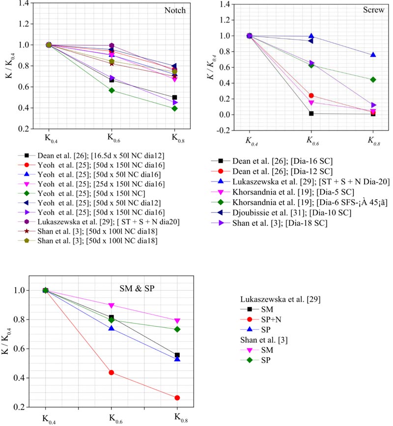 |
Fig. (25). Stiffness degradation. |
4. BENDING PERFORMANCES
The analysis of a composite system is essentially based on the linear elastic behavior (i.e., model from Eurocode 5), non-linear behavior including elastic non-linear, plastic deformation, and long-term behavior at last. The effective bending stiffness (EIeff), determined through the slip modulus, and the strength determined through ultimate load-carrying capacity are parameters that the linear elastic model employs to define all the stresses and deformation in the composite system [10, 53]. The effective bending stiffness (EIeff) of a composite system is, therefore, a function of the slip modulus and material properties such as the elastic modulus (E) of the joist and the flange (concrete slab, and timber or bamboo beam), and the moment of inertia (I) (i.e. cross-sectional properties).
As far as the elastic model is concerned, it is true that the slip modulus remains the base to determine the effective bending stiffness (EIeff) and composite efficiency. Higher slip modulus provides higher bending stiffness (EIeff) and higher composite efficiency. The slip modulus, on the other hand, is a function of the material bonding property. The strength property of shear connectors is important to transfer shear force; however, it does not directly affect the stress distribution nor the deformation as the design is supposed to guarantee the necessary strength. If the strength requirements are not satisfied, the failure of the composite system could be directly due to the failure of the connectors. Therefore, consider the strength property of shear connectors would be as significant as the slip modulus.
Concluding, the properties of materials that constitute the composite are important factors that influence the elastic linear behavior and the structural performance of a composite. This requires the comparative study of structural performances of the two composites (the TCC and BCC) systems, so that better alternative solution can be found to realize sustainable construction practice, particularly to the composite system.
4.1. BCC Beams
Two series of full-scale bending tests on bamboo-based composite were performed by Shan et al. [54] and Deresa et al. [4]. Shan et al. [54] conducted bending test on 8000 mm bamboo-concrete composite (BCC) using 112 mm × 380 mm (width × depth) glubam beam (glubam from thin bamboo strips) and 900 × 100 mm (width × depth) concrete using various shear connectors. Similarly, Deresa et al. [4] conducted a bending test on a 3600 mm long composite beam made of glubam (from thick bamboo strips) and recycled aggregate concrete (RAC) slab. The bamboo-recycled aggregate concrete composite (BRACC) or glubam-recycled aggregate concrete composite (GRACC) is composed of a glubam joist of 60 mm × 300 mm (width × depth) and recycled aggregate concrete flange of 1000 mm × 100 mm (width × depth) connected using screw and notch shear connectors. The RAC slab is manufactured with 30% recycled aggregate (RA) replacing the natural aggregate (NA). This percentage was chosen based on research findings from literature on the effect of recycled aggregate for structural applications. Accordingly, up to 30% replacement of RA does not significantly affect the compressive strength and structural performances of concrete.
4.2. TCC Beams
Yeoh et al. [28] conducted a full-scale bending test on eleven timber concrete composite beam specimens of 800 mm and 10000 mm long made of laminated veneer lumber (LVL) timber beam and concrete slab, using several types of shear connectors. In the study, various parameters were considered. Notch connections reinforced with screws, varying the length and shape of notch, and continuous steel mesh was used as shear connector. Construction and concrete type were also tested parameters. For convenient comparison, test results of the LVL-concrete composites of those with similar shear connectors and those specimens with closer property to the BCC are selected herein for comparison.
Fig. (26) shows cross-section of the composite and connection details adopted in Yeoh et al [28]. The LVL joist has a 63 mm width and 400 mm height while the concrete slab is 600 mm wide and 65 mm depth with 17 mm plywood under the concrete slab. The notch length in LVL-concrete composites is 150 mm and 300 mm.
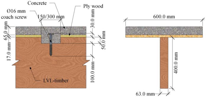 |
Fig. (26). Cross-section and connection details. After Yeoh et al [28]. |
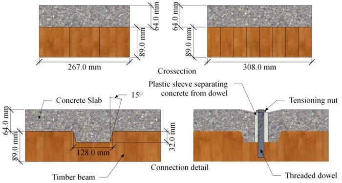 |
Fig. (27). Cross-section and connection details. After Gutkowski et al [24]. |
Van der Linden et al. [8] conducted a bending test on TCC beams of each 5700 mm long constructed from glulam as timber beam and concrete slab made of concrete grade C-25. Three types of shear connectors were used including notch reinforced with dowels of Ø20 mm and screw arranged inclined at ± 45Ø. The timber beam was 100 mm tick and 200mm deep, while the concrete slab was 70 mm thick and 600 mm wide.
Gutkowski et al [24]. conducted bending test on layered TCC of rectangular cross-section using notch shear connector reinforced with dowels. The bending test specimens had a span of 3510 mm with two types of cross-sectional configurations: i) concrete slab size of 305 mm × 64mm, and timber beam size of 305 mm × 89 mm: ii) concrete slab size of 267 mm × 64 mm, and timber beam size of 267 mm × 89 mm. Fig. (27) shows cross-sectional configuration and connection details adopted in Gutkowski et al [24].
Lukaszewska et al. [11, 31] conducted a full scale bending test on 4800 mm long TCC using several types of shear connectors among which, SST+SC, is one. The screw arrangement in the test specimen with this type of shear connector is close to those of the BCC beams with the screw connection. The SST+SC shear connector consists of Ø20 mm hexagon-head lag screws with a length of 160 mm screwed into steel tubes that is inserted into the concrete slab to connect the slab to the timber beam (glulam) with the steel tube fixed totally in the concrete slab. The shear connectors are spaced at 250 mm and 500 mm c/c. Fig. (28) shows the cross-sectional details of the specimens tested: ‘M’ shaped made of concrete slab size of 60 mm × 1600 mm (depth × width) and three 90 mm × 270 mm (depth × width) glulam joists spaced at 600 mm c/c.
Quang Ma, et al. [42] conducted a full scale bending test on cross-laminated timber-concrete (CLT) composite using different types of shear connectors. Five specimens of rectangular cross-section with size of 900 mm ×6000 mm (width × length) with 150 mm depth of timber and 100 mm depth of concrete topping were tested. Shear connectors of Ø10 mm coach screw and Ø7.5 mm SFS with length of 180 mm and 145mm were used at different orientations (i.e., ± 45Ø and 90Ø). Fig. (29) shows the longitudinal view of the screw arrangement.
 |
Fig. (28). Cross-section of specimen tested in Lukaszewska et al. [31]. |
 |
Fig. (29). Connection details used in Quang Ma, et al. [42]. |
Derikvand et al. [43] experimentally investigated the bending capacity of TCC system made of nail laminated timber (NLT) and concrete under short-term bending test using Ø7.4 mm and 145 mm long SFS screw inclined at 45Ø as shear connector. The composite beams are prepared in two different arrangements of the NLT as shown in Fig. (30) below.
Table 4 presents summary of connection and cross-sectional details of the composite specimens. For instance, in the column ‘Shear Connector description’, 32dx128l NCØ16 (4) indicates a notch of depth 32 mm, length 128 mm reinforced with a dowel of Ø16 mm and the total number of the notch in the tested beam is 4. Similarly, for the screw connection, the diameter, type, orientation and spacing of screws are specified. While, in the column ‘connector’, ‘NC’-represents the notch and ‘SC’-represents the screw connector each followed by specimen number and the first letter of the author’s name. Furthermore, t-signifies timber thickness, h-height of timber; d-depth of concrete, w-width of concrete slab, E-elastic modulus of (timber/glubam and concrete) and fc the compressive strength of concrete.
It is worth mentioning that different properties of the connections such as the notch length, the cut depth, the cut inclination, and screw diameter, screw length and screw orientation do have impacts on the structural performance of the composite system. However, the focus of this study is not to evaluate how these features of the connector affect the structural performance, but to give an insight of the structural performance of bamboo-concrete composite as compared to the well-known TCC system.
| Connector | Shear Connector description | Cross-sectional detail of the composite | ||||||
|---|---|---|---|---|---|---|---|---|
| Timber | Concrete | |||||||
| t [mm] | h [mm] | Et [MPa] | w [mm] | h [mm] | Ec [MPa] | fc [MPa] | ||
| Timber-concrete, Van der Linden et al. [8] | ||||||||
| SC-1-V | Screw | 100.00 | 200.00 | N/A | 600.00 | 70.00 | 25000.00 | 25.00 |
| NC-1-V | 30dx70l NCØ20 (18) | 100.00 | 200.00 | N/A | 600.00 | 70.00 | 25000.00 | 25.00 |
| Timber-concrete, Gutkowski et al. [24] | ||||||||
| NC-1-G | 32dx128l NCØ16 (4) | 267.00 | 89.00 | 1210.00 | 267.00 | 64.00 | 26700.00 | 24.00 |
| NC-2-G | 32dx128l NCØ16 (4) | 305.00 | 89.00 | 1250.00 | 305.00 | 64.00 | 26700.00 | 24.00 |
| LVL-composite, Yeoh et al. [42] | ||||||||
| NC-1-Y | 25d x150l NCØ16 (6) | 63.00 | 400.00 | 11340.00 | 600.00 | 65.00 | 33400.00 | 49.6 |
| NC-2-Y | 25d x150l NCØ16 (6) | 63.00 | 400.00 | 11340.00 | 600.00 | 65.00 | 33400.00 | 49.6 |
| NC-2-Y | 25d x150l NCØ16 (10) | 63.00 | 400.00 | 11340.00 | 600.00 | 65.00 | 33400.00 | 49.6 |
| NC-3-Y | 50d x 300l NCØ16 (6) | 63.00 | 400.00 | 11340.00 | 600.00 | 65.00 | 33400.00 | 42.6 |
| NC-4-Y | 50d x 300l NCØ16 (6) | 63.00 | 400.00 | 11340.00 | 600.00 | 65.00 | 33400.00 | 41.5 |
| LVL-composite, Lukaszewska et al. [31] | ||||||||
| SC-1-L | SST+S (250mm) | 90.00 | 270.00 | 10700.00 | 1600.00 | 60.00 | 34525.00 | 44.60 |
| SC-2-L | SST+S (500mm) | 90.00 | 270.00 | 10700.00 | 1600.00 | 60.00 | 34525.00 | 48.20 |
| CLT-concrete composite Quang Ma, et al. [42] | ||||||||
| CLT | CLT-only | 600.00 | 150.00 | 12000.00 | - | - | - | - |
| SC-1-Q | B-± 45Ø -s (150mm) | 600.00 | 150.00 | 12000.00 | 600.00 | 100.00 | 27029.00 | 27.29 |
| SC-2-Q | SFS- 90Ø -s(150mm) | 600.00 | 150.00 | 12000.00 | 600.00 | 100.00 | 27029.00 | 27.29 |
| SC-3-Q | SFS-± 45Ø -s(150mm) | 600.00 | 150.00 | 12000.00 | 600.00 | 100.00 | 27029.00 | 27.29 |
| SC-4-Q | SFS-± 45Ø -s(300mm) | 600.00 | 150.00 | 12000.00 | 600.00 | 100.00 | 27029.00 | 27.29 |
| NLTC Derikvand et al. [43] | ||||||||
| NLT-1 | NLT | 280.00 | 140.00 | 10800.00 | - | - | - | - |
| SC-1-D | Ø7.5 SFS-± 45Ø-s (200mm) | 280.00 | 140.00 | 10800.00 | 280.00 | 60.00 | 28351.40 | 32.00 |
| SC-2-D | Ø7.5 SFS-± 45Ø-s (200mm) | 280.00 | 140.00 | 10800.00 | 280.00 | 60.00 | 28351.40 | 32.00 |
| SC-3-D | Ø7.5 SFS-± 45Ø-s (200mm) | 280.00 | 140.00 | 10800.00 | 280.00 | 60.00 | 28351.40 | 32.00 |
| NLT-2 | NLT | 280.00 | 140.00 | 11300.00 | - | - | - | |
| SC-4-D | Ø7.5 SFS-± 45Ø-s (200mm) | 280.00 | 90.00 | 11300.00 | 280.00 | 110.00 | 28351.40 | 32.00 |
| SC-5-D | Ø7.5 SFS-± 45Ø-s (200mm) | 280.00 | 90.00 | 11300.00 | 280.00 | 110.00 | 28351.40 | 32.00 |
| SC-6-D | Ø7.5 SFS-± 45Ø-s (200mm) | 280.00 | 90.00 | 11300.00 | 280.00 | 110.00 | 28351.40 | 32.00 |
| Bamboo-concrete composite, Shan et al. [54] | ||||||||
| SC-1-S | Ø18 Screw (100mm) | 112.00 | 380.00 | 9400.00 | 900.00 | 100.00 | 29000.00 | 30.00 |
| SC-2-S | Ø18 Screw (100mm) | 112.00 | 380.00 | 9400.00 | 900.00 | 100.00 | 29000.00 | 30.00 |
| NC-1-S | 50d x 100l NCØ18 (12) | 112.00 | 380.00 | 9400.00 | 900.00 | 100.00 | 29000.00 | 30.00 |
| NC-2-S | 50d x 100l NCØ18 (16) | 112.00 | 380.00 | 9400.00 | 900.00 | 100.00 | 29000.00 | 30.00 |
| NC-3-S | 50d x 200l NCØ18 (8) | 112.00 | 380.00 | 9400.00 | 900.00 | 100.00 | 29000.00 | 30.00 |
| NC-4-S | 50d x 200l NCØ18 (12) | 112.00 | 380.00 | 9400.00 | 900.00 | 100.00 | 29000.00 | 30.00 |
| BRAC composite, Deresa et al. [4]. | ||||||||
| NC-1-D | 50d x 100l NCØ18 (13) | 60.00 | 300.00 | 10400.00 | 1000.00 | 100.00 | 30314.33 | 40.00 |
| SC-1-D | Ø18 Screw (100mm) | 60.00 | 300.00 | 10400.00 | 1000.00 | 100.00 | 30314.33 | 40.00 |
| GLB | Glubam-only | 60.00 | 300.00 | 10400.00 | - | - | - | - |
 |
Fig. (30). Cross-section of specimen tested in Derikvand et al. [43]. |
4.3. Material Used to Manufacture the TCC and BCC System
The concrete used in all the studies can be classified as normal concrete with medium strength class. Yeoh et al [28]. used LVL as timber joist with mean Young’s modulus (Et) of 11340 MPa, bending strength (fb) of 46.84 MPa and tensile strength (ft) of 33.38 MP and weights around 8 KN. Gutkowski et al. [24] used a timber beam from ‘Spruce Pine-Fir specie’ which is reported as surface-green and of ‘Standard and Better’ grade. The concrete slab is with an average compressive strength of 24 MPa and an average unit weight of 22,660 KN/mm3. Lukaszewska et al. [31] used a glulam of strength class GL32 with Young’s modulus of (Et) 10,700 MPa and bending strength of (fb) 47.9 MPa; and mean density of 457.9 Kg/m3. Self-compacting concrete (SCC) with strength class of C20/25, and mean density of 2,331.9 Kg/m3 was used to manufacture prefabricated concrete slab. Note that Yeoh et al [28]. and Lukaszewska et al [31]. used prefab-concrete slab in their TCC systems. Quang Ma et al. [42] used a cross-laminated timber beam which is made of a cross-laminated five lamina of each 30 mm thick, forming a timber beam of total thickness 150 mm. The CLT used were with the mean Young’s modulus (Et) 12000 MPa, bending strength (fb) of 12.4 MPa and tensile strength (ft) 8.2 MPa. The laminae are bonded with structural adhesive to strongly bond the timber layer. The average compressive strength of the concrete slab was 27.29 MPa. Derikvand et al. [43] used nail-laminated timber (NLT) which is an engineered mass laminated timber product. It is prepared from two types of wood plantations obtained from low grade, eucalyptus nitens (NLT-1) and eucalyptus globulus (NLT- 2). The former is with a mean Young’s modulus (Et) of 10,800 MPa and the later with 11,300MPa, having weight that ranges 7.5-9KN. Normal concrete with compressive strength of 32 MPa was used to manufacture the concrete slab.
Table 5 presents the material properties of Bamboo-Concrete composites as obtained from material tests of the glubam. The presented material property descriptions in the timber-concrete and bamboo-concrete composites indicate that materials used to manufacture both composites have comparable mechanical properties except that the bending and tensile strength properties of glubam and timber. These two properties are special welfares that the glubam offers to the Bamboo-concrete composite.
4.4. Comparison of Bending Test Results
4.4.1. Comparison of the Failure Mode
Similarly, Deresa et al. [4] reported that the final failure of BRAC composite beams with the notch shear connector is exclusively characterized as flexural tensile failure of the glubam. The failure phenomenon observed can be explained that the glubam beam failed in tensile fracture and the bamboo strips pulled-off. Also, shearing off the glubam due to delamination cracking that extended from the base of the last notch to one end was also observed. By contrast, Shan et al. [54] reported that the global failure of the BCC is attributed to the connection failure for specimens with the notch series with inclined cracking of concrete and plasticization of screw in the notch. As can be seen from Fig. (31) concrete crushing inside the notch due to shear has occurred in both composite systems. However, the extent of the concrete damage is somehow larger in the TCC system. It should be noted that the connection system in the BRACC is designed in such a way that it has to provide sufficient strength so that there should be no connection failure during the collapse test. Indeed, the failure observed indicated that the required condition was met. The notch adopted in the BRAC composite is cut inclined at 150 from the vertical. The inclination angle is supposed to provide an advantage to avoid the stress concentration of a right angle at the base of the notch and proper placement of concrete during casting of the slab [24].
Fig. (31) presents pictures showing the failure mode of the timber-concrete and BCC composites. Yeoh et al [28]. reported two types of failure mode for the notch connection: i) for under-designed connection, composite beams showed connection failure due to shear or crushing of concrete with plasticization of the coach screw in the notch: ii) for the well-designed connection, the global failure of the composite system is essentially attributed to tensile failure of the LVL joist in the constant bending zone. Gutkowski et al [24]. reported failure mode that can entirely characterize as the initial flexural tensile failure of the timber beam in the span with the maximum moment region. The study findings presented herein indicate that the global failure of the TCC system with a sufficiently designed notch shear connector (reinforced with either screw or dowels) is essentially attributed to the tensile fracture of the timber joist in the span between the two loading points.
Van der Linden et al. [8] reported similar failure modes for the composites with both the notch and screw connectors. Firstly, concrete cracks are observed in the maximum tension zone with further widening and development of additional cracks upon increasing the load. Secondly, a gap between the timber beam and concrete slab occurred at a location near the support, at one end. The gap increased as the load increased. After this, for the notch connection, the timber beam split at the notch near the last connector at one end. Shear block failure of the concrete in the notch is also noticed which is described as a failure similar to that of the ring and shear-plate connection in timber to timber connections. Finally, the global failure of the composite beams, with both the screw and notch shear connectors, is governed by the tensile failure of the timber beam. Similarly, the failure phenomena of TCC system presented by Lukaszewska et al. [31] with screw connection also characterized as a typical tensile fracture of the timber joist. Lukaszewska et al. [31] highlighted that no apparent damage was observed on the screw, but the wood around the connector showed minor signs of embedment failure. Quang Ma, et al. [42] reported a combined tensile and shearing type of failure. The tensile failure occurs at the lower part on the first layer of the timber while shearing happened at the interface of the laminate at the maximum moment zone. As the load increased, shearing due to delamination at the interface of each layer subsequently progressed to the next transverse layer. It is mentioned that there was no significant failure observed in the concrete slab except a few hairline cracks in the maximum moment zone. Derikvand et al. [43] also reported a tensile failure of the timber beam leading to the global failure of composite beams.
| Glubam | In-plane Longitudinal Compressive Strength (MPa) | Perpendicular to Plane Compressive Strength (MPa) | In-plane Longitudinal Tensile Strength (MPa) | Bending Strength (MPa) | Density (kg/ m3) | Elastic Modulus (MPa) |
|---|---|---|---|---|---|---|
| Shan et al. [54] | 54 | 68 | 80 | 94 | 880 | 9,400 |
| Deresa et al [4]. | 24 | 73 | 85 | 108.9 | 900 | 10400 |
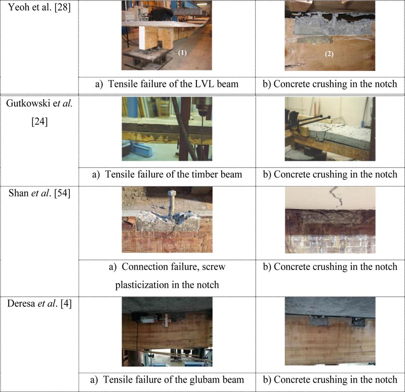 |
Fig. (31). Failure pattern of the composite beams. |
On the other hand, the BCC beams with screw shear connectors showed a different failure mode compared with the TCC system. The global failure observed in both the BCC and BRAC composites with screw connection is somehow similar and can, exclusively, be characterized as a sheared type of failure due to the delamination cracking of the bamboo strips in the glubam sheet. Fig. (32) shows some representative samples of the failure mode of TCC reported in the cited literature and bamboo-concrete composite beams with a screw shear connector.
4.4.2. Effect of Concrete Characteristics
The global failure of a composite system may occur for the failure of the concrete slab. For instance, Gutkowski et al [24]. indicated that one of the beams failed due to the upward buckling of the concrete slab which separated it from the timber beam and then led to concrete crushing. The upward buckling of the concrete slab is also observed in one of the test specimens in the BRACC composite with the notch connection, but there was no severe crushing in the concrete slab. The concrete slab slightly buckled to upward as the load approached the peak. This phenomenon happened in the BRACC spacemen with the notch connection, but it was not that significant to be the reason for the beam’s failure. A similar case was also reported in Van der Linden et al. [8] and Derikvand et al. [43] tests, but mentioned that it was not the reason for the global failure of the TCC system.
 |
Fig. (32). Failure of the composites with screw connections. |
There was no substantial damage on the RAC slab which could create global failure in glubam-RAC composite until the maximum load is reached. In fact, cracks initiated as the load increased. The commonly observed damage was hairline cracks dominantly formed in the maximum moment zone, and inclined concrete crack inside the notches. Inclined cracks of the concrete are dominantly seen in notches that are located in the shear span. Yeoh et al. [28] mentioned that concrete strength can meaningfully affect the shear strength of the connection and hence the load-carrying capacity of composite beams. The result obtained from the bending test of bamboo-RAC composites, however, evidenced that the employment of the recycled aggregate concrete in the composite beam is not affecting the performance of the composite. Rather the load-carrying capacities (which will be discussed in subsequent sections) of BRAC composites were found to be comparable or perhaps better than the TCC system manufactured with normal concrete as almost all the global failures in both composites were attributed to the failure of the joist (glubam/timber).
4.4.3. Comparison of Load-bearing Capacity
As mentioned earlier, structural performances of the composite system are a function of material properties of the joist and the flange, stiffness of the connection and geometry of the composite, etc. The structural performances of BCCs and TCCs summarized in the abovementioned literature cannot be directly compared. However, an effort is made to have a rational comparison of the basic structural performances such as the load-carrying capacity, degree of composite action and the maximum mid-span deflection.
The comparison of the load-carrying capacity is done in two ways. In a first way, the overall load-carrying capacities of the TCC and the BCC at collapse and SLS load levels are compared, as obtained from the test. For a convenient comparison, the experimental and analytical maximum loads in KN are converted to 'w' in KN/m using bending moment equivalent equation,
 and then to ‘W’ in KN/m2 by dividing 'w' by the width of the slab. While the SLS load levels are converted to ‘w’ in KN/m using equivalent bending deflection criterion, 5wL4/384EI = Pa(3L2 -4a2)/24EI, where a is the shear span in a four point bending, and then to ‘W’ in KN/m2 by dividing 'w' by the width of the slab. This helps to allow, somehow, reasonable comparisons of the load composites.
In a second way, the specific load-carrying capacity (SLC) of each composite system is compared. SLC is the load-carrying capacity of the composite per unit of the self-weight of the composite. For this purpose, the collapse load (2Pc) is divided by the total weight of the composite (i.e., weight of the glubam/ timber + weight of concrete). Note that in the design of structures, apart from the load-carrying capacity, a careful selection of material for different structural applications can be made on the basis of the specific load-carrying capacity [43]. Therefore, SLC provides a more intelligent comparison among the composites and also among each specimen. SLC is given by [43]:
 |
(1) |
Where, SLC is the specific load-carrying capacity (N/N); 2Pc is the collapse load (N) and, G denotes the weight of the composite specimen tested (N). The weight of specimens is obtained directly from literature or calculated from the densities of each material (glubam/timber and concrete). For the timber, Yeoh et al. [28] and Lukaszewska et al. [31] have provided the weight and density, respectively, while the densities of timber (Spruce-Pine-Fir) in Gutkowski et al [24]. and the CLT in Quang Ma, et al. [42] were taken from [55] and [56], respectively. Similarly, the density of concrete is obtained directly from the literature if provided, as in the case [24, 31], or predicted from the compressive strength of the concrete using [57]:
 |
(2) |
where ρ is the density of the concrete in Kg/m3 and fc is the compressive strength in MPa. The model used to predict the density of the concrete slab is normally used for the normal concrete, and it is directly applied to predict the density of the recycled concrete slabs used in [4]. Recycled aggregate concrete has a slightly lower density when compared to the normal concrete for the same concrete grade.
Table 6 presents experimental and analytical load levels at collapse and serviceability limit states taken from the corresponding literature mentioned thereon the table, the converted collapse and SLS loads, W, in KN/m2, and the specific load-carrying capacity, SLC, in N/N. Fig. (33) presents comparisons of the experimental and analytical (to those reported in the literature) of maximum load capacities (collapse load) and load level at serviceability limit states of the TCC and bamboo-based composite system with notch connection.
| Connection | Connection Description | Exp. Collapse Load 2Pc [KN] | Anal. Max. Load 2P [KN] | Exp. Collapse Load Wc [KN/m2] | Anal. Max. Load Wu [KN/m2] | Exp. SLS 2P [KN] | Anal. SLS 2P [KN] | Exp. SLS W [KN/m2] | Anal. SLS W [KN/m2] | SLC [N/N] |
|---|---|---|---|---|---|---|---|---|---|---|
| Timber-concrete, Gutkowski et al. [24] | ||||||||||
| NC-1-G | 32dx128l NCØ16 | 29.5 | N/A | 41.97 | N/A | N/A | N/A | N/A | N/A | 16.61 |
| NC-2-G | 32dx128l NCØ16 | 29.8 | N/A | 37.11 | N/A | N/A | N/A | N/A | N/A | 14.69 |
| LVL-composite, Yeoh et al. [42] | ||||||||||
| NC-1-Y | 25d x150l NCØ16 | 87.3 | 49.68 | 25.19 | 13.8 | 41.2 | 41.2 | 12.15 | 12.15 | 10.19 |
| NC-2-Y | 25d x150l NCØ16 | 75.3 | 49.68 | 21.73 | 13.8 | 41.2 | 41.2 | 12.15 | 12.15 | 8.79 |
| NC-3-Y | 25d x150l NCØ16 | 105 | 67.8 | 30.30 | 18.83 | 52.12 | 47.9 | 15.38 | 14.13 | 12.26 |
| NC-4-Y | 50d x 300l NCØ16 | 80.8 | 81.6 | 23.32 | 22.67 | 49.3 | 45.08 | 14.54 | 13.30 | 9.64 |
| NC-5-Y | 50d x 300l NCØ16 | 79.6 | 45.9 | 18.24 | 10.2 | 30.15 | 23.24 | 7.06 | 5.44 | 7.77 |
| LVL-concrete, Lukaszewska et al. [31] | ||||||||||
| SC-1-L | Ø20 Screw (250mm) | 308.2 | 138.06 | 57.85 | 23.97 | 92.04 | N/A | 16.33 | N/A | 25.44 |
| SC-2-L | Ø20 Screw (500mm) | 295.9 | 132.5 | 55.54 | 23 | 88.3 | N/A | 15.67 | N/A | 24.43 |
| CLT-concrete, Quang Ma, et al. [42] | ||||||||||
| CLT | CLT-only | 61.22 | N/A | 23.46 | N/A | 24.4 | N/A | 9.24 | N/A | |
| SC-1-Q | Ø10B-± 45Ø | 247.32 | N/A | 94.76 | N/A | 98.6 | N/A | 37.33 | N/A | 21.74 |
| SC-2-Q | Ø7.5 SFS-± 45Ø | 234.79 | N/A | 89.96 | N/A | 93.44 | N/A | 35.38 | N/A | 20.64 |
| SC-3-Q | Ø7.5 SFS-± 45Ø | 152.12 | N/A | 58.28 | N/A | 60.24 | N/A | 22.81 | N/A | 13.37 |
| SC-4-Q | Ø7.5 SFS-90Ø | 170.45 | N/A | 65.31 | N/A | 68.22 | N/A | 25.83 | N/A | 14.99 |
| NLTC, Derikvand et al. [43] | ||||||||||
| NLT-1 | - | 60.25 | N/A | 86.94 | N/A | 11.68 | N/A | 17.23 | N/A | |
| SC-1-D | Ø7.5 SFS-± 45Ø | 89.68 | N/A | 129.41 | N/A | 43.3 | N/A | 63.87 | N/A | 69.13 |
| SC-2-D | Ø7.5 SFS-± 45Ø | 69.63 | N/A | 82.89 | N/A | 19.02 | N/A | 23.15 | N/A | 38.51 |
| SC-3-D | Ø7.5 SFS-± 45Ø | 81.32 | N/A | 117.34 | N/A | 39.43 | N/A | 58.16 | N/A | 62.69 |
| NLT-2 | - | 68.56 | N/A | 98.93 | N/A | 11.85 | N/A | 17.48 | N/A | |
| SC-4-D | Ø7.5 SFS-± 45Ø | 81.99 | N/A | 118.31 | N/A | 46.64 | N/A | 68.8 | N/A | 34.47 |
| SC-5-D | Ø7.5 SFS-± 45Ø | 58.5 | N/A | 69.64 | N/A | 18.6 | N/A | 22.63 | N/A | 17.65 |
| SC-6-D | Ø7.5 SFS-± 45Ø | 75.08 | N/A | 108.34 | N/A | 42.33 | N/A | 62.44 | N/A | 31.57 |
| BCC, Shan et al. [54] | ||||||||||
| SC-1-S | Ø18 Screw (100mm) | 128.6 | 185.18 | 24.43 | 35.17 | 49.2 | 65.928 | 9.55 | 12.80 | 6.54 |
| SC-2-S | Ø18 Screw (100mm) | 166.4 | 206.34 | 31.60 | 39.19 | 56.5 | 68.93 | 10.97 | 13.38 | 8.46 |
| NC-1-S | 50d x 100l NCØ18 (12) | 107.6 | 204.44 | 20.44 | 38.83 | 51 | 64.77 | 9.90 | 12.58 | 5.47 |
| NC-2-S | 50d x 100l NCØ18 (16) | 123.3 | 197.28 | 23.42 | 37.47 | 55 | 66.55 | 10.68 | 12.92 | 6.27 |
| NC-3-S | 50d x 200l NCØ18 (8) | 121.3 | 205.00 | 23.04 | 38.94 | 55.4 | 65.926 | 10.76 | 12.80 | 6.17 |
| NC-4-S | 50d x 200l NCØ18 (12) | 148.1 | 205.86 | 28.13 | 39.10 | 58 | 68.44 | 11.26 | 13.29 | 7.53 |
| BRACC, Deresa et al. [4] | ||||||||||
| NC-1-D | 50d x 100l NC-1-Ø18 | 180 | 234.31 | 72.73 | 94.67 | 105 | 138.52 | 43.37 | 57.41 | 17.66 |
| SC-1-D | Ø18 SC-1 | 186.9 | 238.71 | 75.52 | 96.45 | 110 | 141.17 | 45.43 | 58.52 | 19.75 |
| GLB | Glubam-only | 72.86 | 89.2 | 490.64 | 600.67 | 18 | 20.63 | 123.91 | 142.02 | 327.75 |
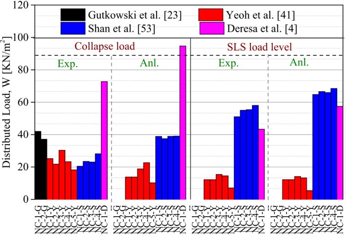 |
Fig. (33). Comparison of the experimental and analytical load of TCC and bamboo-based composite system with notch shear connector. |
In Fig. (33) the analytical loads were predicted such that all the inequalities in the short-term for the ULS are satisfied using the γ-method with connection secant slip modulus, K0.6. In the analysis, strength values of the glubam/timber, concrete and connection were used. As can be seen in Fig. (33), for the notch, the experimental collapse load of the TCC reported by Yeoh et al. [28] and the BCC reported by Shan et al. [54] is almost comparable. Note that the specimens have almost equal span and comparable correctional property. However, it is not possible to compare the collapse load of BRACC reported by Deresa et al. [4] to the TCC system as there is a significant difference in the span of the tested beams. The ‘γ-method’ of prediction of the load capacities in short-term ULS underestimates the actual load capacities of the TCC in Yeoh et al. [28]. On the other hand, the ‘γ-method’ overestimates the actual load-carrying capacity of the bamboo-based composites as the experimentally obtained load capacities are lower than the predicted value.
The experimental and analytical SLS load levels of the TCC and bamboo-based composites are load levels corresponding to the deflection limit of l/300, which is set in Eurocode 5. The effective bending stiffness, (EI) eff, obtained from the γ-method with connection secant slip modulus of K0.4, and mean Young’s moduli of materials (i.e. concrete and LVL/glubam) is used to predict the analytical short-term SLS load level such that the abovementioned deflection limit was satisfied. The experimental load levels being the experimentally obtained load level corresponding to the specified deflection limit.
The γ-method provided a conservative prediction of short-term SLS load levels in Yeoh et al [28]. By contrast, the method overestimated SLS load levels for bamboo-based composite. The reason for this overestimation stems from the fact that glubam members exhibit relatively higher deformation under bending due to the inherent flexibility of bamboo. As can be seen from Fig. (33), it is evident that BCC load capacities are about twice larger TCC.
Fig. (34) presents the comparison of experimental collapse and SLS load levels of composite beams with screw shear connectors. For this connection, the comparison of the load capacities for the bamboo-based and the TCC is made to the experimental test results as the analytical SLS and ULS load levels could not be fully obtained from the literature. Note that in Derikvand et al. [43] and GRAC composite beams, the SLS load levels are considered to be the load level corresponding to the deflection limit of l/300. While Lukaszewska et al. [31] and Quang Ma, et al. [42] the experimental SLS load levels were considered to be 30% and 40% of the maximum experimental load levels, respectively. As clearly seen from Fig. (34), the load-carrying capacity of the bamboo-based, particularly the BRAC one, is comparatively lower than the TCC system.
The analytical predictions show an overestimation of the experimental results of the bamboo-based composite. It is worth to mention that some limitations could exist due to insufficient test data used for structural design purposes. The effective bending stiffness used to estimate the stress at the limit states is based on the approximate solution of the differential equation for beams with partial composite action. It also assumes that the load-slip curves for the connection stiffness are linear though it is pronounced non-linear. Overall, problems associated with the model can better be addressed using artificial intelligence and machine learning techniques [58-62].
A rational comparison of the two composites and even among each specimen can be made using the specific load-carrying capacity. The SLC can be higher as a result of higher load-carrying capacity or due to lower weight. For various structural applications, a relatively lower weight but higher load-carrying capacity is preferable. A composite with lower SLC as a consequence of higher weight is problematic because it can cause extreme reaction forces in structural elements such as columns and support beams that are supposed to carry a combination of different loads including the permanent loads that are a result of the self-weight of the structural elements over them [43]. Therefore, from this point of view, it can be clearly seen from Fig. (35) that bamboo-based composite has a comparable load-carrying capacity to the TCC system and can fairly replace the TCC in many structural applications as a sustainable and economical construction material.
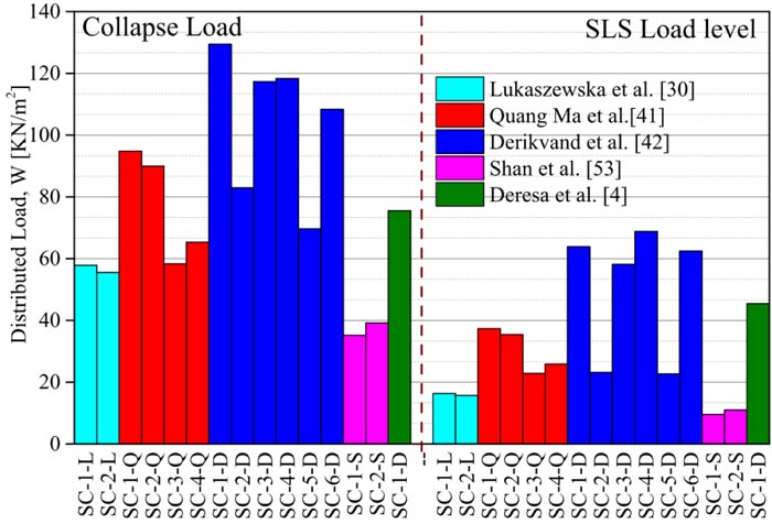 |
Fig. (34). Comparison of Experimental collapse load and SLS load levels of TCC and BCC system with screw shear connector. |
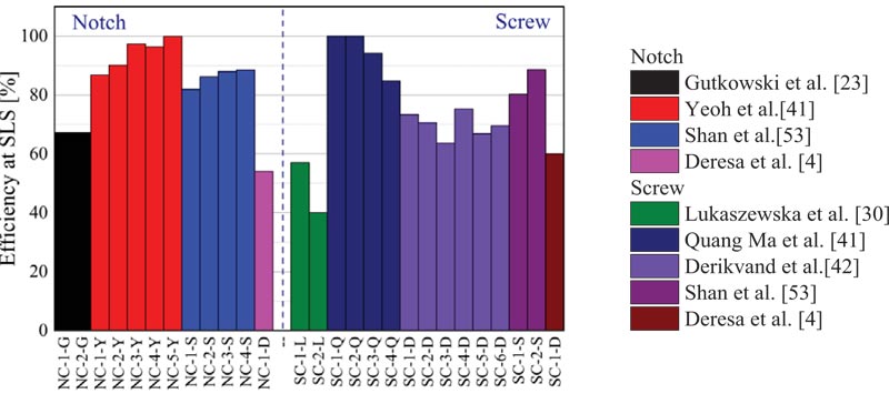 |
Fig. (35). SLC of TCC and the BCC. |
4.4.4. Comparison of Composite Action and Maximum Deflection
The degree of composite action in a composite system indicates how strong and stiff a connection is compared to the fully-rigid one. A high-degree of composite action may be achieved through increasing the number of shear connectors used or using larger diameter connectors. However, this may result in a system that might be uneconomical. Therefore, an optimized solution between the structural requirements and cost should be found.
Table 7 and Fig. (36) present the degree of composite action for the two composites. Yeoh et al. [28] and Quang Ma, et al. [42] reported a higher degree of composite action in the TCC system, which is almost near the fully-rigid one. Shan et al. [54] reported a fairly high composite efficiency. The level of composite action in the TCC system obtained by Lukaszewska et al [31]. was the least. Gutkowski et al [24]. and Derikvand et al. [43] reported somehow moderate efficiency which is comparable to BRACC reported by [4]. Concluding that the degree of composite action obtained in the BCC at SLS load levels can be considered as good as the TCC system investigated by the aforementioned researchers.
| Connection | Connection description | Composite efficiency at SLS (%) | leff [mm] | Δ at SLS, l/300 [mm] | Exp. Δmax [mm] | Δmax/ (l/300) Ratio [%] | ||
|---|---|---|---|---|---|---|---|---|
| Exp. | Anal. | Ratio Exp. /Anal. | ||||||
| Timber-concrete Gutkowski et al. [24] | ||||||||
| NC-1-G | 32dx128l NCØ16 | 67.2 | N/A | N/A | 3510 | N/A | N/A | N/A |
| LVL-composite Yeoh et al. [42] | ||||||||
| NC-1-Y | 25d x150l NCØ16 | 86.8 | 96.8 | 0.9 | 7700 | 25.67 | 64.1 | 40.04 |
| NC-2-Y | 25d x150l NCØ16 | 90.1 | 96.5 | 0.93 | 7700 | 25.67 | 63.2 | 40.61 |
| NC-3-Y | 25d x150l NCØ16 | 97.3 | 97.8 | 0.99 | 7700 | 25.67 | 63.1 | 40.68 |
| NC-4-Y | 50d x 300l NCØ16 | 96.3 | 98.4 | 0.98 | 7700 | 25.67 | 48.1 | 53.36 |
| NC-5-Y | 50d x 300l NCØ16 | 99.9 | 98.8 | 1.01 | 9700 | 32.33 | 93.8 | 34.47 |
| Timber-concrete Lukaszewska et al. [31] | ||||||||
| SC-1-L | Ø20 SC-1 | 57 | N/A | N/A | 4440 | 14.8 | 54.53 | 27.14 |
| SC-2-L | Ø20 SC-2 | 40 | N/A | N/A | 4440 | 14.8 | 60.93 | 24.29 |
| CLT-concrete composite Quang Ma, et al. [42] | ||||||||
| CLT | CLT | - | - | - | 5800 | 19.33 | 100.26 | 19.28 |
| SC-1-Q | Ø10B-± 45Ø | 100 | N/A | N/A | 5800 | 19.33 | 74.77 | 25.86 |
| SC-2-Q | Ø7.5 SFS-± 45Ø | 100 | N/A | N/A | 5800 | 19.33 | 79.28 | 24.39 |
| SC-3-Q | Ø7.5 SFS-± 45Ø | 94.19 | N/A | N/A | 5800 | 19.33 | 63.86 | 30.27 |
| SC-4-Q | Ø7.5 SFS-90Ø | 84.72 | N/A | N/A | 5800 | 19.33 | 110.53 | 17.49 |
| NLTC Derikvand et al. [43] | ||||||||
| NLT-1 | NLT | - | - | - | 3300 | 11 | N/A | N/A |
| SC-1-D | Ø7.5 SFS-± 45Ø | 73.38 | N/A | N/A | 3300 | 11 | N/A | N/A |
| SC-2-D | Ø7.5 SFS-± 45Ø | 70.56 | N/A | N/A | 4600 | 15.33 | N/A | N/A |
| SC-3-D | Ø7.5 SFS-± 45Ø | 63.57 | N/A | N/A | 3300 | 11 | N/A | N/A |
| NLT-2 | NLT | - | - | - | 3300 | 11 | N/A | N/A |
| SC-4-D | Ø7.5 SFS-± 45Ø | 75.22 | N/A | N/A | 3300 | 11 | N/A | N/A |
| SC-5-D | Ø7.5 SFS-± 45Ø | 66.81 | N/A | N/A | 4600 | 15.33 | N/A | N/A |
| SC-6-D | Ø7.5 SFS-± 45Ø | 69.5 | N/A | N/A | 3300 | 11 | N/A | N/A |
| BCC, Shan et al. [54] | ||||||||
| SC-1-S | Ø18 Screw (100mm) | 80.2 | 92.23 | 0.87 | 7800 | 26 | 114.6 | 4.41 |
| SC-2-S | Ø18 Screw (100mm) | 88.6 | 97.46 | 0.91 | 7800 | 26 | 109.9 | 4.23 |
| NC-1-S | 50d x 100l NCØ18 (12) | 81.9 | 94.185 | 0.87 | 7800 | 26 | 95.7 | 3.68 |
| NC-2-S | 50d x 100l NCØ18 (16) | 86.2 | 93.096 | 0.93 | 7800 | 26 | 84.7 | 3.26 |
| NC-3-S | 50d x 200l NCØ18 (8) | 87.9 | 94.932 | 0.93 | 7800 | 26 | 85.9 | 3.30 |
| NC-4-S | 50d x 200l NCØ18 (12) | 88.5 | 96.465 | 0.92 | 7800 | 26 | 81.3 | 3.13 |
| BRAC composite, Deresa et al. [4] | ||||||||
| NC-1-D | 50d x 100l NC-1-Ø18 | 54 | 49.5 | 0.89 | 3300 | 11 | 24.57 | 44.77 |
| SC-1-D | Ø18 SC-1 | 60 | 56 | 0.92 | 3300 | 11 | 24.08 | 45.68 |
| GLB | Glubam-only | - | - | - | 3300 | 11 | 63.22 | 17.4 |
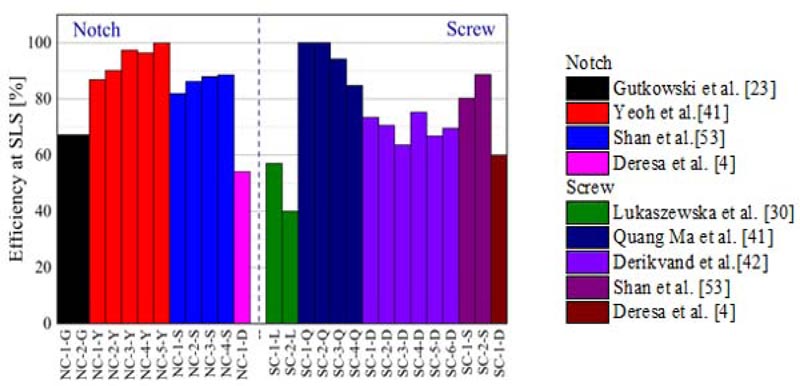 |
Fig. (36). Comparison of composite efficiency at SLS load level. |
The maximum deflection of the BCC is also compared to the TCC system. Table 7 presents the ratio of the maximum deflection to the deflection limit at SLS of the composites. A higher value of this ratio indicates a relatively lower bending capacity of the composite; however, the comparison for this property can be done for specimens with equal span. Accordingly, The result reported by Yeoh et al. [28] for the TCC, and Shan et al. [54] for the BCC indicates that the bamboo-based composite has higher bending capacity than the TCC.
CONCLUSION
This paper presented a rational comparison of the mechanical properties of connections and bending performances of TCC to the BCC system based on the experimental results available in the literature. In the comparison, only experimental results of TCC and BCC system with similar types of shear connectors are considered. Based on the comparison, the following conclusions can be drawn:
Mechanical properties of connections:
- The failure modes of TCC and BCC systems with screw and all types of the notch shear connectors are essentially similar. BCC with the continuous steel mesh and folded steel plate shear connector exhibited different failure phenomena from the TCC system. In BCC, the delamination cracking of the glubam beam is deemed to be the main reason for the failure of specimens with these types of shear connectors.
- The strength and stiffness properties of the bamboo-concrete composite are either fairly comparable or even better than the TCC. Generally, BCC has better stability in terms of stiffness degradation when compared to the TCC.
Bending performance of the composite system:
- The failure mode for a specimen with a notch shear connector can be exclusively attributed to the tensile failure of the joist for both the TCC and BCC system given that the connection system is well-designed. By contrast, BCC with a screw shear connecter exhibited different types of failure mode from the TCC system with an exclusively sheared type of failure due to the delamination cracking of the bamboo strips in the glubam sheet. The use of recycled aggregate in the concrete slab has shown no effect in the failure mode of the composite as the failure of all composite in the BRAC composite is attributed to the failure of the glubam beam.
- The ultimate load-carrying capacity of the bamboo-based composite can be considered as comparable to the TCC systems. However, the SLC of BCC seems to be slightly lower. But it needs further study because limited researches are available on the BCC. The γ-method over-estimates the load-carrying capacities of the BCC systems at SLS load levels as compared to the TCC.
- The BCC showed a comparable composite efficiency as compared to TCC systems with better bending capacity.
Finally, this comprehensive review indicates that BCC beams have similar or even better structural performances compared with TCC. The future application of BCC beams to large scale should be explored by developing more research and fabrications techniques.
CONSENT FOR PUBLICATION
Not applicable.
FUNDING
None.
CONFLICT OF INTEREST
The authors declare no conflict of interest, financial or otherwise.
ACKNOWLEDGEMENTS
Declared none.


