All published articles of this journal are available on ScienceDirect.

BIM Structural Project Applied in A Case Study: Interoperability Analyses, Reinforcement Detailing Drawings and Quantity Take-off
Abstract
Background:
The Building Information Modelling (BIM) methodology has been acquiring, worldwide, a growing acceptance in all sectors of the Construction industry, and the study intends to contribute to its implementation within the structural design. The fundamental concept of BIM is based on the generation of a centralized virtual model with all information concerning different specialties. This is supported in efficient interoperability, but within the structural design, this aspect is difficult to achieve completely, as currently, the interoperability of this system is still inefficient.
Introduction:
This study intends to analyze the degree of interoperability verified in the development of all the processes (modelling, transposition, structural analyses and reinforcement detailing) involved in a structural design using BIM tools.
Methods:
A structural project concerning a study case was performed in order to identify benefits and limitations, based on the consistency analysis of the transposed data between systems, Revit and Robot, in all steps required in a BIM process. This text describes the stages of modelling, checking the suitability of the analytical model, its transference to the analysis tool in order to proceed with the structural calculations and detailing drawings and, finally, the transfer of drawings to the main BIM model.
Results:
The limitations verified in the last stage were partially surpassed with complementary work enabling the automatic transfer of drawings and quantities of materials. In addition, the study explores new capacities of BIM, namely, the extraction of information allowing the presentation of specific drawings and maps of the geometry of the reinforcement rods.
Conclusion:
This study identifies a working strategy that leads to an appropriate use of BIM software contributing to the optimization of labor in a structural office.
1. INTRODUCTION
The Building Information Modelling (BIM) methodology involves as a basic concept the generation of a digital model, a three-dimensional (3D) representation of the building [1]. The BIM model is created and updated throughout the development of the project, and elaborated using the available support tools. The information generated in the process is centralized in a single virtual model, which allows an internal organization of data according to hierarchical levels, suitable for a directed retrieval of data by specialty, element or material. After defining the different components of the project of a building or infrastructure, BIM tools easily access the model database, allowing the manipulation of the information required in the execution of diverse types of activities, usually elaborated over the project documentation, such as graphic representation, quantification of materials and budgeting [2] or construction planning [3]. The BIM methodology, based on the centralization of information and the advanced technology tools available, allows the team involved in the project to collaborate under the same platform. This capacity leads to the reduction of errors and conflicts in processes where data transfer is required between steps, resulting in cost savings involved in the different phases of the life cycle of a building, from design to maintenance [4].
The information contained in the model is introduced in the form of parametric objects representative of construction components, in which the parameters basically involve the geometric perspective, but also the characterization of their behavior through the values of mechanical properties associated with the applied materials. In the context of the structural design, the parametric objects used to model a structural solution for a building correspond essentially to slabs, pillars, beams and foundations. And the properties necessary to perform the structural analyses are related to concrete and steel, such as modulus of elasticity, Poisson coefficient and volume weight.
Using BIM modelling tools, the structural engineer must first generate a parametric model, and then he must transpose it to a BIM structural calculation software in order to validate the established structural frame and to produce the correspondent graphic documentation. The concept of centralizing all data in a BIM model requires that the structural model is first transposed from the modelling system to the analysis tool and then from this tool to the modelling software. These transfer processes require a heightened level of interoperability capacity of the tools. After the structural analyses are processed, the detailed information concerning the calculation result, including the reinforcements detailing, must be fully transferred to the initial BIM model, completing the initial structural model. The major problem normally verified in the development of a BIM structural project is the inefficient interoperability identified in this final step.
Currently, the tools available do not yet incorporate a sufficiently efficient level of interoperability, which provides correct data identification between steps, without inconsistencies, omissions or data errors. This investigation aims to detect the limitations that arise in each step of the transposition of models between systems and to analyze which solutions or strategies are most appropriate to minimize the frequent inaccuracies inherent in the BIM process [5].
Along with the benefits that have been recognized in relation to BIM implementation in the construction industry, its adoption within the companies, enterprises and project offices requires an effort in technology investment and in training. In addition, significant re-organizational changes related to the internal cultural adaptation concerning work modes, data transfer processes between phases and communication with partners are also required [6].
At the University of Lisbon, several Masters theses were concluded concerning BIM applied in the structural design; Serra [7] used the advancing infrastructure of Bentley and has made an in-depth analysis of the consistencies of the analytical models before and after transposition; Azevedo [8] focused on the transposition of the Revit model to the SAP structural system, performing two-way data flow; Novais [9] studied the interoperability of the Revit and Robot systems, with the focus on the application of loads and its correct transfer between tools; Oliveira [10] referred also to the Revit and Robot systems, detected and tried to resolve the problems mainly concerning the transposition of reinforcements; Farinha [11] explored the Graphisoft and CSI companies, in particular, using the ArchiCAD and ETABS tools, demonstrating inefficient interoperability. Rodrigues [12] described the main difficulties in terms of interoperability that still remain in the analysis process, also using the Revit and Robot systems. It is recognized that the limitations of interoperability are associated with the BIM systems, and mainly concern the two-way data flow processes required throughout the elaboration of a complete structural project [13-15].
The mentioned academic researches were the main bases of the Master thesis elaborated by Borges [16], in order to add new achievements, also developed in the same University. The present text highlights the most relevant components and achievements concerning the research. The study involving BIM structures context is mainly focused on an important innovative, practical direction, concerning the reinforcement detailing drawings and the quantity take-off of materials in a structural project.
BIM, applied to structural engineering, provides an outstanding opportunity for structural engineers to adopt a collaborative strategy, as it provides technical advantages, such as improved communication with clients and the whole team by speeding up the process of making changes and delivering final products more proficiently [13]. Adopting BIM in structural engineering allows the improvement of efficiency through modelling as it increases the quality of work using parametric change management and improves design flexibility by better accommodating design alternatives and supporting more effective collaboration.
Handling 3D BIM tools makes it easy to analyse multiple alternative options and arrive at a better design in less time as work is supported by digital drawings. The rich data model created in each project allows engineers to quickly test the variability and structural integrity of different options [14]. So, BIM processes can prevent costly and time-consuming errors. These are the most evident benefits but the problem of the interoperability still causes some resistance by collaborators involved in the structural design.
The present study analyses the degree of interoperability in two integrated software programs, the Revit (Autodesk), as the modelling system, and the Robot (Autodesk) with direct access from Revit, as a structural calculation tool. As both belong to the same computer enterprise, the Autodesk, the data is transferred throughout all steps in its native format. This study, based on one building case, explores the modelling and analysis processes regarding the interoperability problems verified in stages where data transfer takes place [16]:
- In Revit, a structural solution is modelled and the correctness of the respective analytical frame is checked;
- The analytical model is transposed from Revit to Robot and its geometric consistency is verified;
- In Robot, the structural analysis is performed and the reinforcement drawings are defined;
- In order to centralize all information in the first model, the reinforcement rods obtained from the calculation are transferred from Robot to Revit, and the correctness of the data is checked;
- In Revit, the model is complemented and distinct types of drawings and maps are automatically obtained.
In all these steps, the diagnostic of the interoperability efficiency is verified with the objective of listing the tasks that should be made in one or other software, with the guarantee of correctness. The main objective of the work is to support the specification of a useful guide for structural engineers. For that, a structural problems background retrieved from the bibliography is first made, followed by the modelling process of the building being studied and its transposition in order to perform the structural analysis. After that, the results, in the form of 3D models, diagrams, reports and drawings, are considered for transfer to the main or federated model. The identification of the problems, difficulties, gaps, misunderstandings and omissions, is carefully reported, and the most relevant remarks are presented as conclusions. The study demonstrates that, despite the limitations identified throughout the process, essentially related to the problem of interoperability, the methodology has clear advantages in the development of the design of structures under BIM-based platforms.
2. METHODS
2.1. Modelling the Study Case
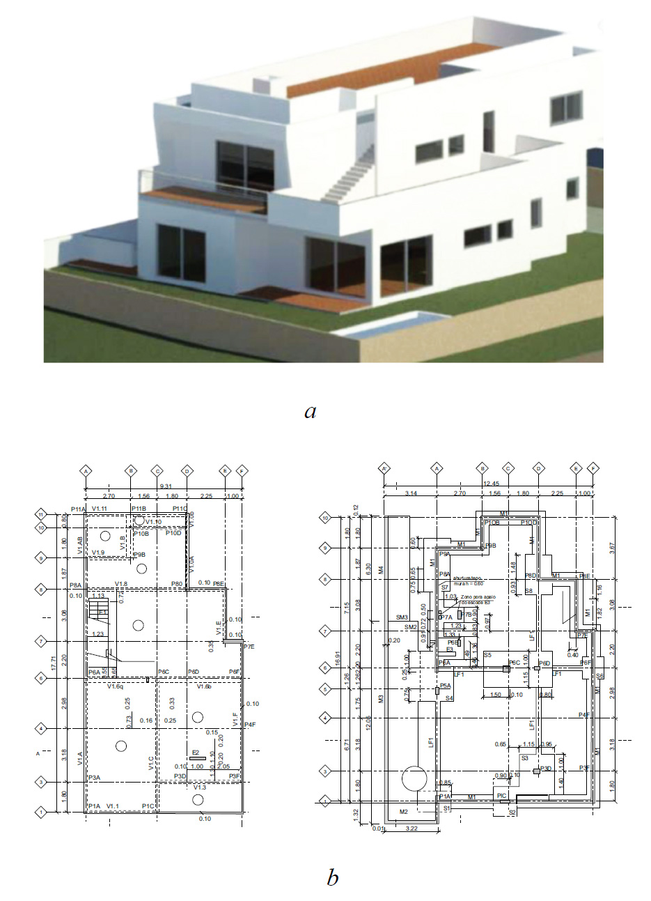
The case study selected for the development of a project of structures in a BIM environment is a single-family house located in Algarve, Portugal (Fig. 1).
The graphic representation of the established structural solution isprovided in the form of digital drawings, and a written report is also provided referring to the calculation method and the initial dimensioning made. The drawn elements, consisting of plants of the structural foundation and the floors, offer the necessary information for the generation of the BIM model representative of the structure.
2.1.1. Structural Solution
Based on the drawings of the structures of the project, the BIM model was generated using the Revit (Autodesk) software. The villa, with 2 raised floors and a basement, requires the initial establishment of 4 modelling levels for the structure (Fig. 2): foundation, floor 0, floor 1 and roof. The structural solution is formed in reinforced concrete.
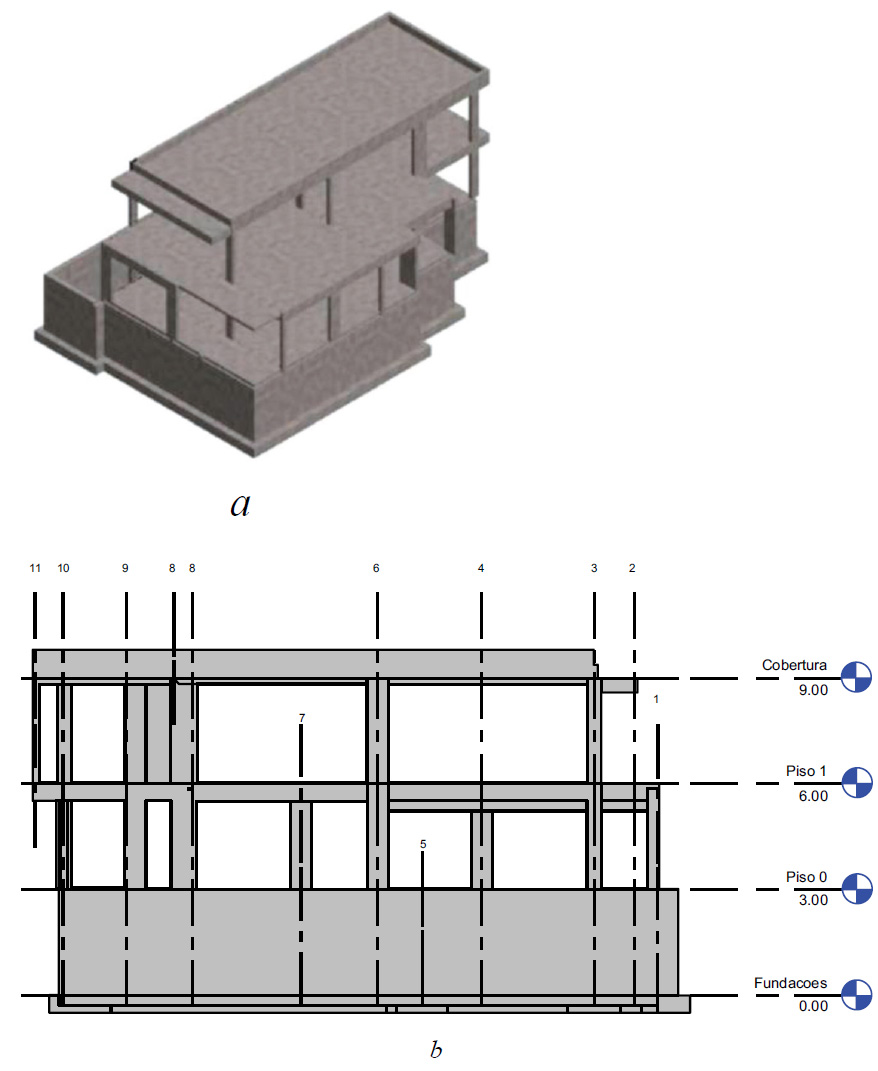
In the generation of the model, the parametric objects used are columns, resistant walls, beams and slabs (Fig. 3), associated with mechanical properties of the materials to be applied, i.e. concrete and steel (Table 1).
| Material | Properties | Material | Properties | ||
|---|---|---|---|---|---|
| Concrete C30/37 | fck(MPa) | 30,0 | A500 NR SD | fyk(MPa) | 500 |
| fcd(MPa) | 20,0 | fyd(MPa) | 435 | ||
| fctm(MPa) | 2,9 | Es(GPa) | 200 | ||
| Ecm(GPa) | 33,0 | 2,18x10⁻³ | |||
| Yc(kN/m3) | 24,0 | >7,5 | |||
| Yc(kN/m3) | 30,0 | ||||
Concrete: fck - Characteristic compressive strength of concrete; fcd - Maximum strength of compressed concrete; fctm - Mean tensile strength of concrete; Ecm - Modulus of elasticity of concrete; Yc - Young's modulus of concrete.
Steel: fyk - Characteristic yield strength of passive reinforcements; fyd - Design strength of steel; Es - Modulus of elasticity of steel; and - relative strain; Ys - Young's modulus of steel.
- The concrete slab presents a solution composed of beams and a unique thickness of 0.16m on all panels of both floors;
- On floor-1, support peripheral walls are arranged, and in the middle, pillars with continuity to the upper levels are considered;
- The foundation is straightforward and consists of running elements placed under the peripheral support walls, and isolated foundations under the pillars positioned in the central zone, interconnected by foundation beams.
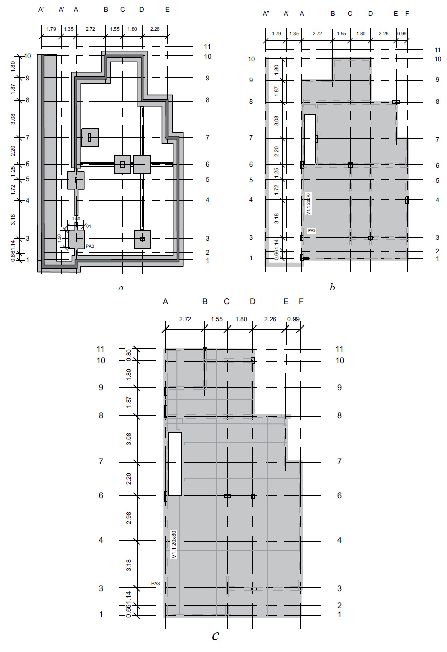
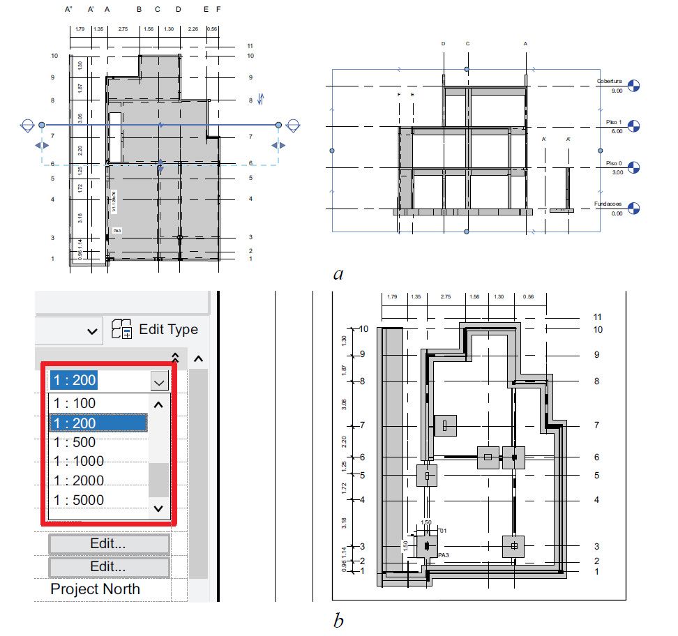
The model generation process is supported by a grid of alignments defined directly over the imported drawings in dwg format (Fig. 4a). The modeling begins with the insertion of all the structural elements, referring to columns, followed by walls, beams (Fig. 4b), slabs, and finally, the foundations (Fig. 4c).
The software used provides libraries of parametric objects concerning structures, each type of element being selected and adapted to the dimensions of the sections (Table 2) and thicknesses desired and associated with the respective material, with a correct assignment of its mechanical properties.
An element, belonging to a structural family, contains the information necessary for its analytical discretization. A beam is discretized according to its axis (Fig. 4a), being associated with the area of its cross-section and inertia, characteristics necessary in the structural analyses process.
| Family | Concrete-Rectangular | Load |
|---|---|---|
| Type: | V20x30 | Duplicate |
| Rename | ||
| Type Parameters | ||
| Structural | ||
| Section Shape | ||
| Dimensions | ||
| b | 200 | |
| h | 500 |
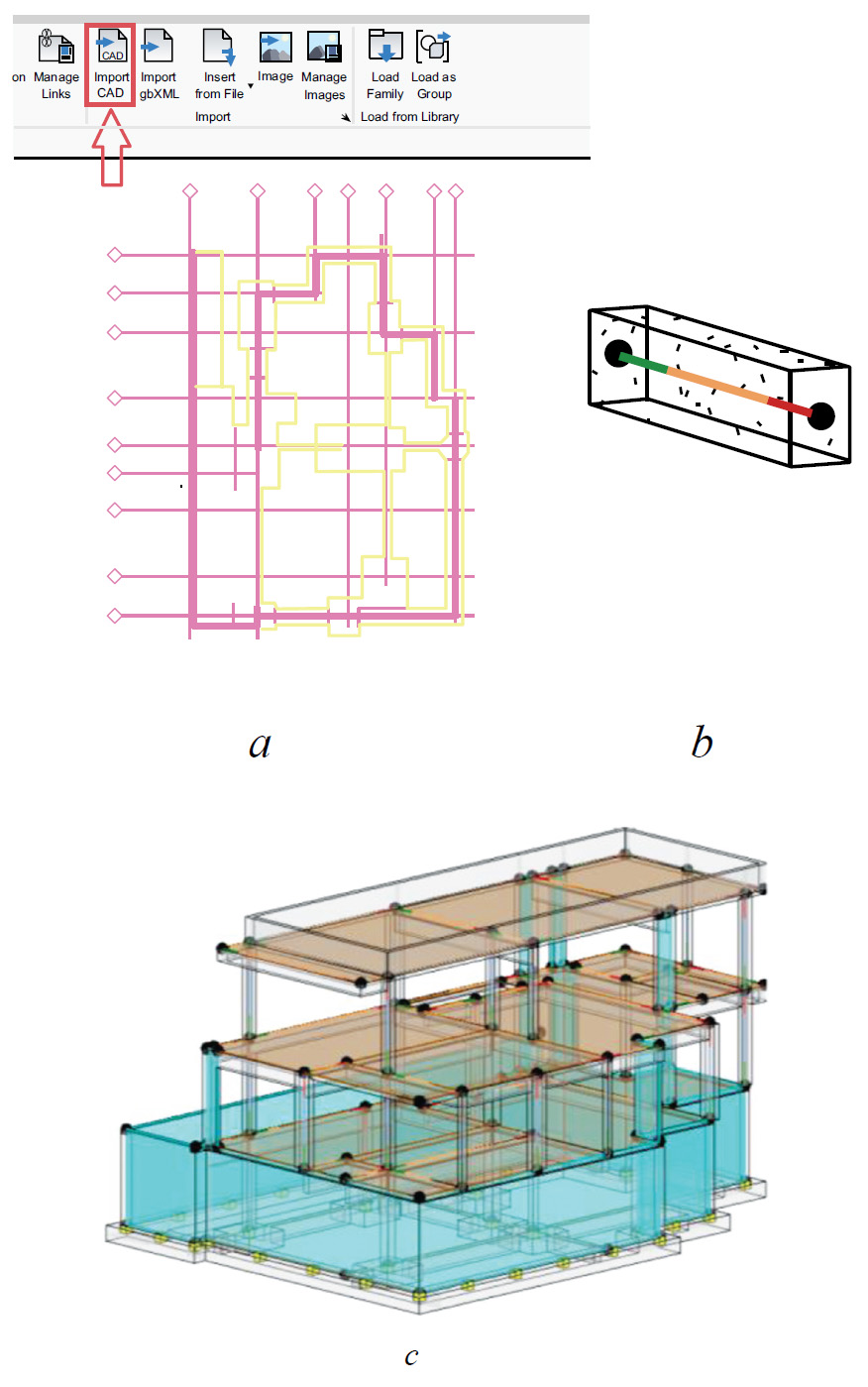
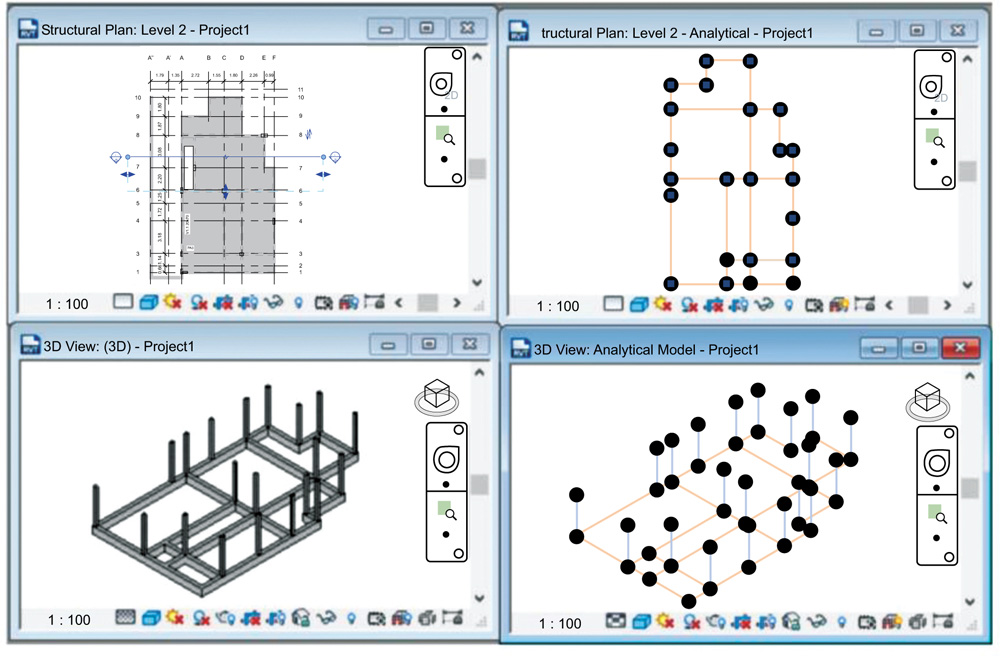
Still, in the modelling system, a first geometric modelling verification is made, in which the consistency of the link nodes between elements isobserved, and eventually, some corrections are made, observing the analytical representation of the structure. At any stage of the modelling process, the software possesses the ability to visualize, with a double image in parallel, the geometric and analytical models, and also the application of error identification filters, supporting the detection of possible inaccuracies in the links between elements, and the modeler must rectify accordingly (Fig. 5).
The representation of the applied loads on the structure can be carried out directly in Revit, allowing the construction of different types of loads, permanent and variable, and the required combinations of loads (Table 3).
However, for the execution of a seismic analysis, only the Robot software is used that allows the correct and complete association of loads and combinations of loads required in the current normalization. Thus, although Revit allows the repre- sentation of most of the loads and the description of almost all combinations, in the present study, the option was to apply all the loads and the combinations in Robot (Fig. 6).
| Load Cases | ||||||||||
|---|---|---|---|---|---|---|---|---|---|---|
| Name | Case Number | Nature | Category | |||||||
| 1 | DL1 | 1 | Dead | Dead Loads | ||||||
| 2 | SC2 | 3 | Live | Live Loads | ||||||
| 3 | SC1 | 4 | Live | Live Loads | ||||||
| 4 | RCP | 2 | Dead | Dead Loads | ||||||
| 5 | Modal | 5 | Dead | Dead Loads | ||||||
| Load Combinations | 4 | |||||||||
| Name | Formula | Type | State | |||||||
| 1 | ELU | 1.35*CL1+1.35*RCP+1.5*RC2 | Comb. | Ultimate | ||||||
| 2 | ELS+CQ | 1.0*CL1+1.0*RCP+0.3*RC2 | Comb. | Service | ||||||
2.1.2. Model Transfer
The process of designing structures requires the use of a structural calculation system. In a BIM process, the structural model is transferred to a structural analyses tool. In the transfer process between systems of distinct software houses, it is necessary to use the universal standard format of data exchange, Industry Foundation Classes (IFC) [17, 18]. However, this pattern still possesses many limitations, causing interoperability problems, which transform into errors, omissions and duplication of data. The recent academic reports presented by Rodrigues [12], Oliveira [10], Novais [9] and Serra [7] reveal a still high level of inefficient interoperability in the design of structures in the BIM environment, when the necessary transposition of data is not carried out in the native format and the IFC format is required.
In the present study, the model created in Revit is transposed to Robot, an analysis tool also from Autodesk. Thus, the native format of data is common, ensuring a high level of interoperability. However, analyzing the consistency of the transposed model, concerning the geometry and the parameters of the objects used in the modelling process, some errors were detected. The errors were, essentially, related to regional incompatibility (USA and Portugal), requiring an adaptation to the Portuguese context. Other inaccuracies were also found, which are as follows:
- Concrete C30/37 maintains the designation, but the values associated with the parameters concerning the mechanical properties require correction;
- Although the information on the dimensions of the sections and thicknesses of the structural elements is correct, their relative location requires an appropriate repositioning. In particular, the upper surfaces of the beams and slabs must be leveled, with the exception of the top floor, where the base of the beams is aligned with the base of the slab;
- The loads defined in the modeling system were transposed with correction, but differing in terms of load combinations, the safety factors were changed and were not properly associated with those of the Last Limit State (LLS) and the Service Limit State (SLS).
After the necessary correction of the transposed model, the structural analysis of the building was then performed, and the efforts were calculated, the pre-dimensioning was verified and the reinforcement detailing was established.
3. STRUCTURAL ANALYSIS
The efforts were determined through a three-dimensional analysis of the structure, considering the linear elastic behavior of the materials and geometric linearity. The calculations carried out complied with the applicable rules, in particular NP EN 1991-1-1 (EC1) Loads in structures (2009) [19], NP EN 1992-1-1 (EC2) Design of concrete structures (2010) [20], e NP EN 1998-1 (EC8) Design of structures for earthquake resistance (2009) [21]. The actions to be applied consider permanent and variable requests:
- The permanent loads account for the dead weight of the structural elements, obtained automatically by the calculation system, based on the volume weight of 77.5kN/m3 of the concrete and 55.0kN/m3 of the steel, and the remaining permanent loads related to the coating and non-structural walls; for the impulse of the land on the foundation walls, the average value of 20kN/m2 was admitted;
- The variable loads consider the normative overload related to the type of use, 2kN/m2 (floors 0 and 1) and 1kN/m2 (roof);
- The load of the earthquake was determined, considering that the building, located in Algarve, is located in a seismic zone equivalent to 1.3 and 2.3 of the Portuguese territory, with accelerations agr=1.5m/s2 and agr=1.7m/s2, respectively, and that the land was classified as being type B.
The combinations of actions were defined following the current standards for the security verification of the Ultimate Limit State (ULS) and for Service Limit State (SLS):
- The structure is verified in relation to the limit states of deformation and splitting, and the control of the splitting is supported in the application of minimum reinforcements, limiting the spacing and diameter of the reinforcements;
- The deformation in the solid slabs and beams is limited to l/250 for the almost permanent combination of loads in current zones, and l/500 in partition wall zones (after their placement).
The permanent loads and variable overload were correctly transposed, while the safety coefficients of the combinations had to be rectified. The combination for seismic action has been added. The Robot system, an application directed to structural calculation, incorporates interfaces of easy application of loads and definition of all required combinations. Thus, as a guide of action, it is recommended to import the model without associated loads and proceed to its application directly in Robot.
3.1. Results of Structural Analysis
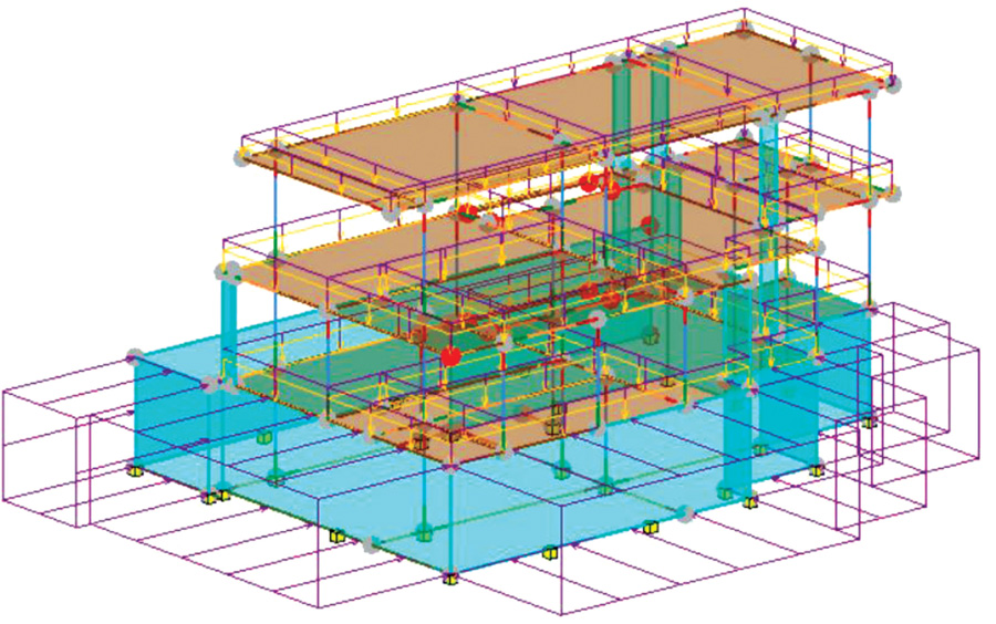
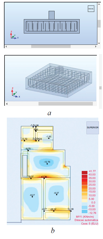
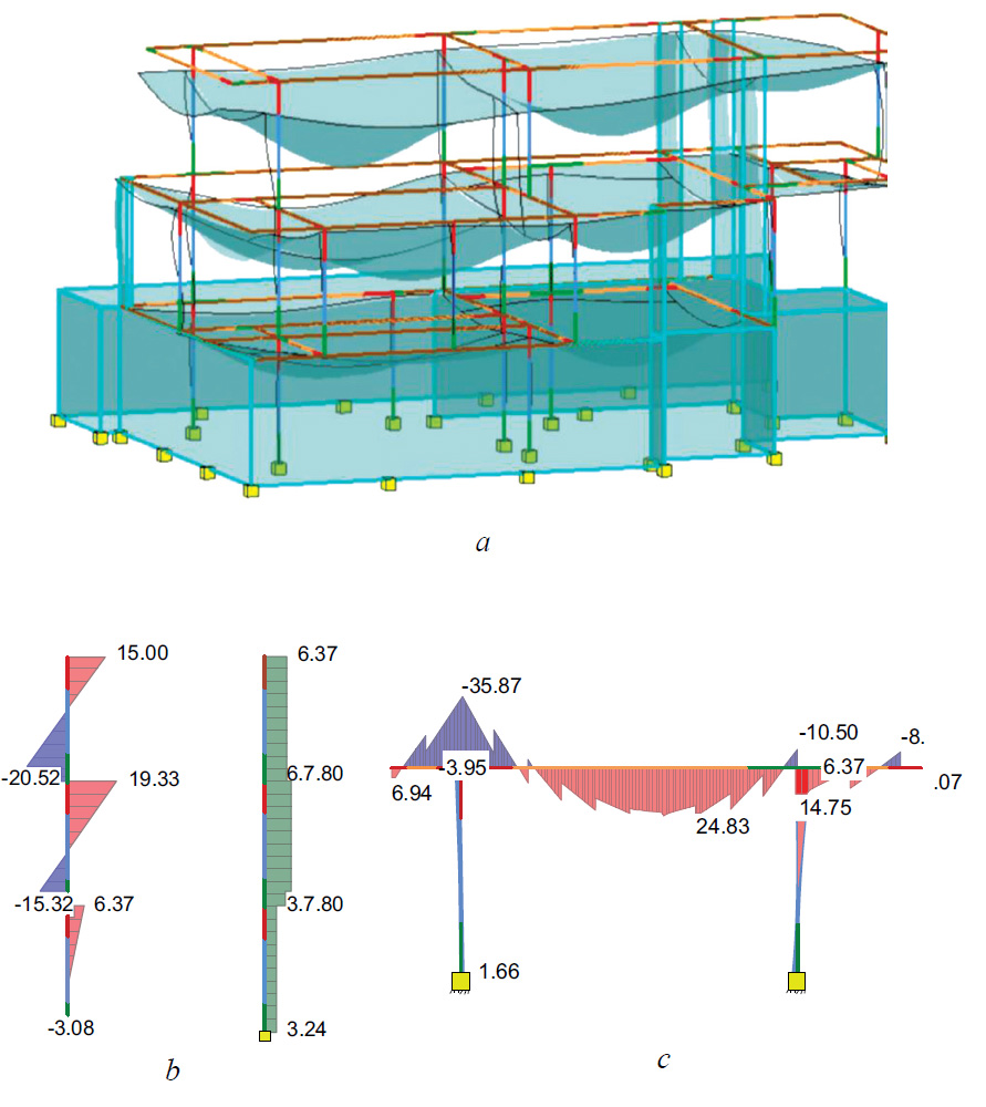
The result of the determination of efforts validates the established pre-sizing of the structural solution. The representation of the efforts is presented by combination and by enveloping all combinations, for the verification of the structure to the ULS and SLS states. Stresses and deformations are represented in the form of two-dimensional diagrams or 3D models (Fig. 7).

In relation to the seismic load, the software performs a dynamic analysis, offering information in the form of tables of numerical values but also through dynamic animations of the vibration modes of the structure (Fig. 8) (Table 4).
3.2. Detailing of Reinforcements
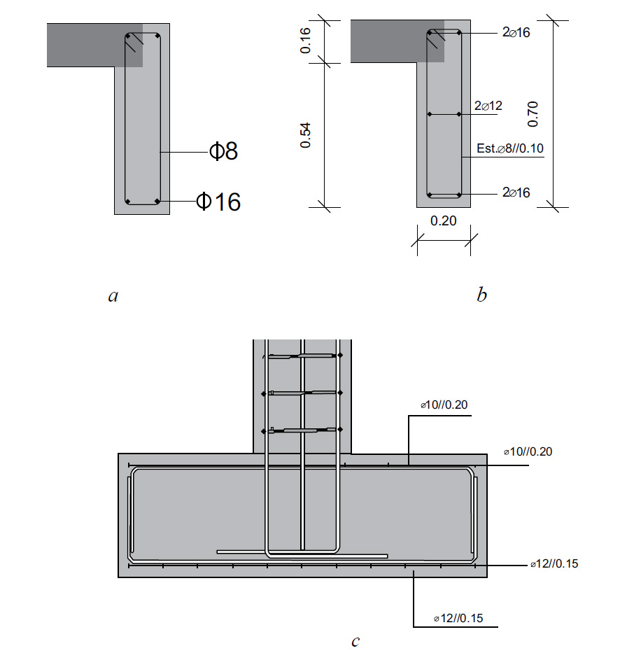
Based on the results of the efforts, the areas of reinforcement required for each element are determined. The software allows the automatic generation of reinforcement detailing, controlled by the values assigned by the designer to the conditioning parameters. Fig. (9) illustrates the detail of the reinforcement to be inserted in the beam VA of floor 0, which is made using the respective interface available in the system, and from the reinforcement area determined (Table 5).
| Mode | Frequency (Hz) | Period (s) | Translation in X | Translation in Y | ||
|---|---|---|---|---|---|---|
| UX (%) | SUX (%) | UY (%) | SUY (%) | |||
| 1 | 3.28 | 0.30 | 46.77 | 46.77 | 3.70 | 3.7 |
| 2 | 3.70 | 0.27 | 16.58 | 63.35 | 23.75 | 24.45 |
| 3 | 4.43 | 0.23 | 0.89 | 64.24 | 55.69 | 83.14 |
| 4 | 8.07 | 0.12 | 34.86 | 99.10 | 0.00 | 83.14 |
| 5 | 8.42 | 0.12 | 0.00 | 99.10 | 6.35 | 83.49 |
| 6 | 12.19 | 0.08 | 0.04 | 99.14 | 9.70 | 99.18 |
| Beam | M (kN.m) |
Med (kN.m) |
As(cm2) nec. | Solution | |||
|---|---|---|---|---|---|---|---|
| b(m) | d(m) | fcd(kPa) | fyd(MPa) | M+min | 24.94 | 0.88 | 2F16 |
| 0.20 | 0.66 | 20000 | 434782.6 | M-max | 32.60 | 1.15 | 2F16 |
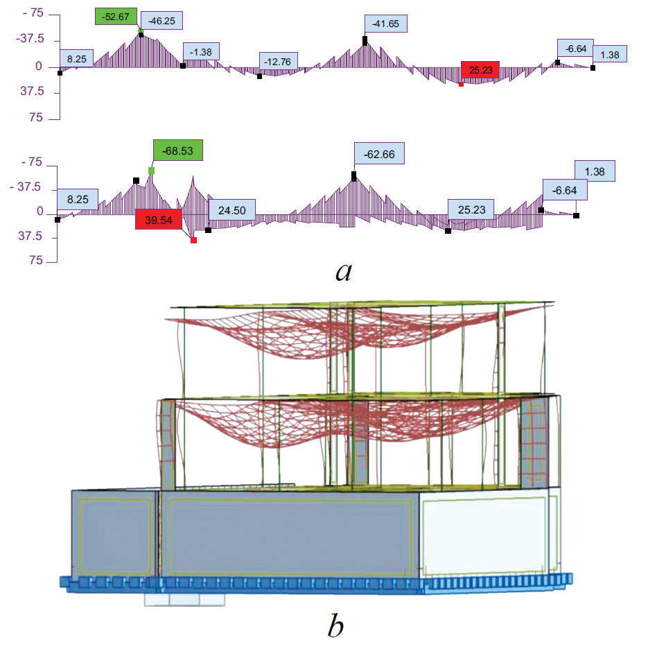
The reinforcements of the basement pillar P1 (marked in Fig. 9) are detailed through its interface and based on the result of the compound deflecting bending effort (Fig. 10).

By using the capabilities inherent in the software in use, it is possible to perform the sizing of foundations and slabs, and the results are presented in the form of tables, diagrams or calculation notes (Fig. 11) (Table 6).
3.3. Transposition of Information on Reinforcements
The BIM methodology involves, as a basic concept, the information generated in the different phases inherent in the development of a project, on a single platform, which may consist of the geometric model and the drawings, tables or reports of structural analysis or energy or environmental simulation. Thus, the results of the structural analyses must be transferred to the initial structural model. This phase has proved to be the most problematic due to the inaccuracies that still remain and despite the technological evolution achieved, these have not yet been suppressed by the latest systems, developed by the software houses, nor by the new versions of the IFC format, incrementally efficient, but still with limitations.
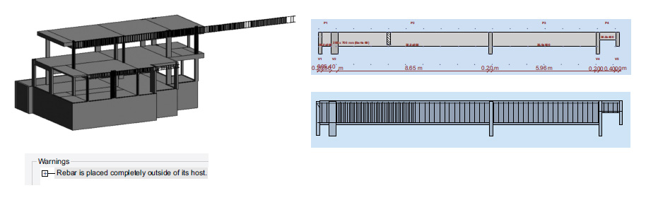
Thus, the transposition to Revit of the information created in the Robot is followed by some inconsistency related to the reinforcements detailing. Fig. (12) illustrates the result of the transposition of the Robot model, and the incorrect identification of the extension of a beam on floor 1 has been verified. The origin of the error lies in the definition, in Robot, of continuous beams by selecting multiple adjacent spans, modelled individually in Revit. When the reinforced beam is transposed, the reinforcement is repeated with the entire length of the continuous beam for each of the individual span. This error is easily adjusted by eliminating the excess elements of the reinforcement.
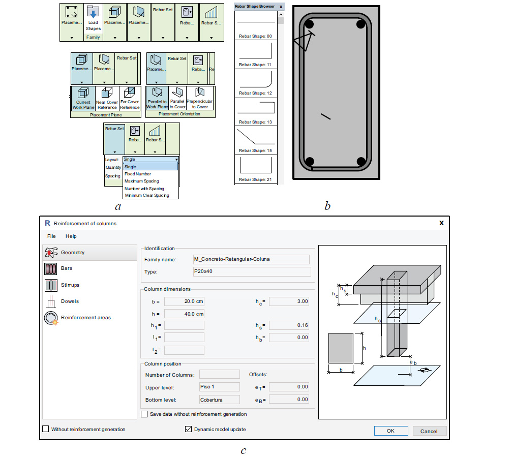
In the transposition process of the structural model, the reinforcements arranged on the foundations are not identified in Revit, because in the transposition initially made, from Revit to Robot, the foundations were assumed, for the purpose of calculation, only as supports without associated dimensions. Additionally, the information created in Robot, relating to the reinforcements distributed on the slabs, is also not recognized in Revit. The solution to overcome the limitations found and complete or define the omitted information in the Revit model, lies in the rectification and completion of the detailing step of the reinforcement representation, using Revit capabilities and associated extensions. Revit involves an application aimed at detailing reinforcements, Extensions Reinforcement (Fig. 13).
The tool allows the generation of reinforcements in an intuitive way and with some automation, facilitating the process of detailing with respect to the type of element. This extension allows the copying of reinforcements between equal elements and, when similar reinforcements are made, the required adjustment is achieved. To support the modelling of the reinforcements, in Revit, the detailed drawings were automatically generated in Robot, as this tool has a high level of detail and features to support the execution of graphic documents (Fig. 14).
| Foundations | As int | As int | As sup | As sup |
|---|---|---|---|---|
| Solution | cm2/m | Solution | cm2/m | |
| Direction xx | F12//0.15 | 7.54 | F10//0.20 | 3.93 |
| Direction yy | F12//0.15 | 7.54 | F10//0.20 | 3.93 |
These representations were archived in the Robot in dwg format and transferred to Revit, serving as the basis for modelling of the missing reinforcements. The structure of the BIM model gets complete with the modelling of the reinforcements on all elements. However, the traditional mode of presentation of the project is carried out in the form of drawn components and reports with result tables obtained from the analyses. This task is easily achieved by using features available in Revit.
3.4. Drawings and Quantities of Reinforcements
The generation of drawings and the obtainment of tables of quantities of material are carried out over the complete and updated final model. BIM tools allow to create and archive perspectives, drawings, and tables on the platform in a dynamic way. That is, drawings are defined, such as projections or sections, applied on the model, and tables as a set of parameters associated with values to be extracted from the model. Thus, as the development of the project involveschanges and adjustments, the drawings and tables are automatically updated. The ability to extract information from the model for the preparation of documents associated with the project or other activities such as budgeting, maintenance planning or management of the building has been recognized as one of the greatest potentialities of the methodology [22]. Drawings and tables are always consistent because they are obtained directly from the model, and they must be updated whenever the model is changed.
3.5. Graphic Documents
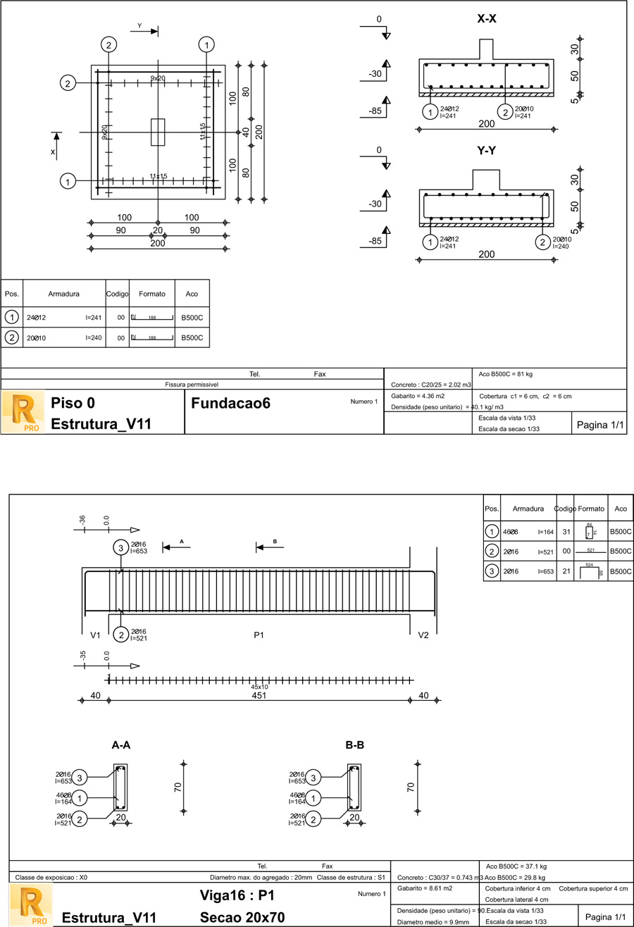
The reinforcements were modelled for all elements, with the help of the Extensions Reinforcement tool, allowing to obtain any type of drawings and tables. Although the transposition of graphics and drawings, from Robot to Revit, still requires significant additional work, there is a considerable volume of documentation production performed automatically in Robot, which is transposed to Revit, allowing to conclude that the execution of technical drawings, using BIM tools, offers significant benefits for the structural designer.
The geometric model is used in the production of drawings, eliminating the individual generation of cuts, elevations and plants, using a CAD system. The model is unique and the drawings correspond to views, cuts or perspectives applied over the model, being archived on the work platform as individual but dynamic schemas (Fig. 15).

Revit is based on the manipulation of families, including those related to the design of lines, text and the application of dimensions (Fig. 16). All annotations to be inserted in each drawing can be adjusted to obtain the presentation usually applied in the graphical documentation of the design of structures. However, mastering this feature requires some user experience to generate and adapt the properties of dynamic blocks in a customized way.
When representing a cross-section of a beam, Revit automatically performs the identification of the reinforcements. However, the design obtained presents only one longitudinal rod annotated and the stirrup is represented as unique. Traditionally, longitudinal bars should all be identified as well as the longitudinal spacing of the stirrups (Fig. 17). Additional work needs to be done on each drawing, but if the cross-section is updated, the annotations are automatically adjusted.
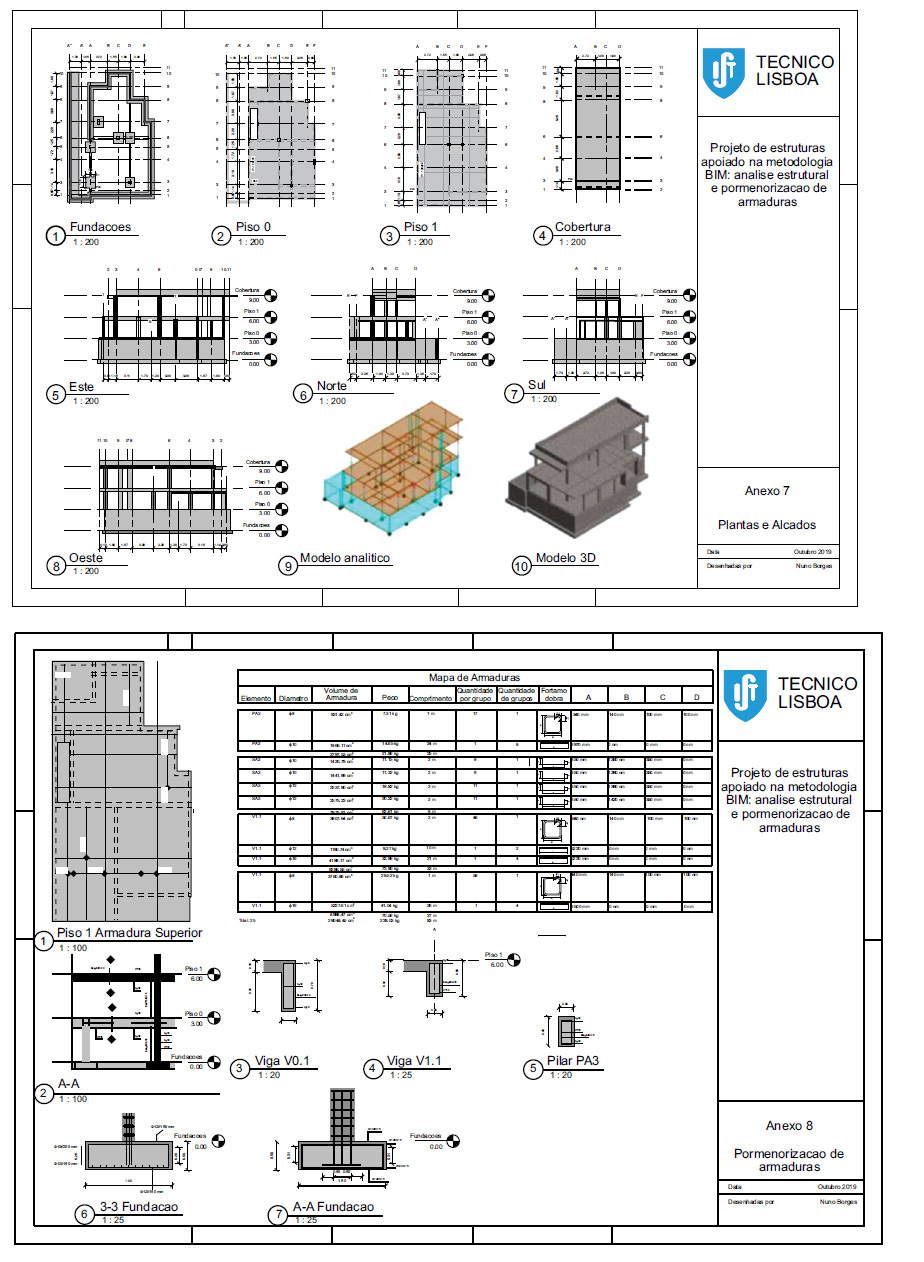
The different drawings or tables can be organized into drawing sheets, which are associated with the project. In the present study, several sheets of drawings were designed for achieving the desired graphics and presentation of structures (Fig. 18).
3.6. Quantity Take-off
In the BIM context, the information generated in the calculation system can be consulted by the engineer and other specialists, and the tables, notes and spreadsheets should be incorporated into a single project platform. Quantity tables can be defined in such a way as to display lists of associated values, elements or materials: material type and quantity; the identification and size of the cross-section or thickness; the mechanical properties of the element or material; values of efforts and their combination of loads.
Quantity take-off (QTO) is a detailed measurement of materials and labor needed to complete a construction project. The numerical and written documentation must be associated with the model, as it constitutes information that is usually incorporated in the supporting calculations of the project. The calculation notes, generated in Robot, are not possible to be attached directly to Revit, but they can be automatically exported to data handling software, like Excel (Microsoft), and text processor, like Word (Microsoft), and later added to the model, as images. However, this format does not allow manipulation, and any update must be made within Robot and afterwards transposed to Revit (Table 7).
| - | Left support | Right Support | Span | x=0.40(m) | x=0.69(m) | x=1.18(m) | x=1.67(m) | x=2.16(m) | x=2.65(m) |
|---|---|---|---|---|---|---|---|---|---|
| M | -32.62 | -3.74 | 24.94 | 0.00 | 0.00 | 0.00 | 7.91 | 16.45 | 22.00 |
| (kN.m) | -32.62 | -20.18 | -4.69 | 0.00 | 0.00 | 0.00 | |||
| Mr | -32.62 | -3.74 | 24.94 | 0.00 | 0.00 | 0.00 | 7.91 | 16.45 | 22.00 |
| (kN.m) | -32.62 | -20.18 | -4.69 | 0.00 | 0.00 | 0.00 | |||
| Mt | -32.62 | 14.54 | 24.94 | 0.00 | 0.00 | 0.00 | 12.85 | 19.70 | 23.70 |
| (kN.m) | -32.62 | -32.32 | -4.69 | -3.77 | 0.00 | 0.00 | |||
| Mc | -63.01 | 63.29 | 63.29 | 29.56 | 63.29 | 0.00 | 63.29 | 63.01 | 62.30 |
| (kN.m) | -63.29 | -63.29 | -4.69 | -63.29 | -29.56 | 0.00 |
Regarding seismic load or modal analysis, Revit only presents the identification of loads and combinations, as the results of the calculation are not likely to be transposed from the Robot. However, these values can be transferred from the Robot in the form of an image, as well as the deformation and stress diagrams, and also added to the model (Fig. 19). This allows data to be consulted by any individual of the project team at any time.
For the purpose of estimating costs relating to the structural component of the work and quantifying the material to be used, the information relating to the concrete and reinforcements of the structure can be presented in the form of dynamic tables, and the fields to be automatically filled must be carefully selected (Table 8).
- Tables are arranged in such a way as to display material quantities, such as concrete volume and the amount of reinforcements per floor or according to element;
- The tables can also contain the costs of the material and the associated human resources, and the unit values should be added as attributes to the parameter objects used in the modelling;
- The unit values to be associated may refer to the cost of the execution of the structure, involving the formwork, the assembly of reinforcements and the required labour.
Revit provides tables created in editable formats and with the possibility of being included in drawings for later printing or transfer between partners. Tables can also be exported as Excel worksheets. Thus, tables can be attached directly to drawing sheets or inserted into the written documentation of the project. These documents are part of the design of structures, and according to the basic concept of the BIM methodology, they must all be incorporated in the model for further consult or manipulation.
In addition, the format maps of each reinforcement can be obtained (Table 9).
| Left Support | Right Support | Span | x=0.40(m) | x=0.69(m) | |
|---|---|---|---|---|---|
| M | -32.62 | -3.74 | 24.94 | 0.00 | 0.00 |
| (kN.m) | -32.62 | -20.18 | |||
| Mr | -32.62 | -3.74 | 24.94 | 0.00 | 0.00 |
| (kN.m) | -32.62 | -20.18 | |||
| Mt | -32.62 | 14.54 | 24.94 | 0.00 | 0.00 |
| (kN.m) | -32.62 | -32.32 | |||
| Mc | -63.01 | 63.29 | 63.29 | 29.56 | 63.29 |
| (kN.m) | -63.29 | -63.29 |
| Element | Diameter | Volume (cm3) | Weight (kg) | Length (m) | Quant. |
|---|---|---|---|---|---|
| PA 3 | F8 | 931.42 | 7.31 | 1.09 | 17 |
| PA 3 | F10 | 1866.11 | 14.65 | 23.76 | 8 |
| Subtotal | 2797.53 | 21.95 | 24.85 | ||
| SA 3 | F10 | 2862.78 | 22.47 | 4.04 | 18 |
| SA 3 | F12 | 5113.13 | 40.14 | 4.11 | 22 |
| Subtotal | 7975.91 | 62.61 | 8.17 | ||
| V0.1 | F8 | 3907.64 | 30.67 | 1.69 | 46 |
| V0.1 | F10 | 1180.74 | 9.27 | 10.44 | 2 |
| V0.1 | F12 | 4198.17 | 32.96 | 20.88 | 4 |
| Subtotal | 9286.55 | 71.80 | 33.00 | ||
| V1.1 | F8 | 3760.86 | 29.52 | 1.29 | 58 |
Automatically, the settings of each element that make up each reinforcement can be displayed, associated with dimensions and the number of elements required. These types of maps are relevant in the preparation of the construction:
- They constitute detailed information supporting the work of cutting and folding in the workplace;
- Alternatively, they can be used in the context of prefabrication of reinforcements executed in the factory, allowing the reduction of the space allocated in the workplace and the time of preparation and assembly in construction.
4. DISCUSSION
The objective of the study was to provide evidence of the main advantages of using BIM tools together with the identification of limitations in order to provide a useful guideline for structural engineers. In the application of the methodology for a real case, it was possible to identify relevant benefits:
- The high modelling capacity to generate structural solutions composed of parametric objects, the possibility of studying alternative solutions and the ability to represent the model in a geometric and analytical form allowing its verification before proceeding with its analysis;
- The transfer of models between systems, modelling and analyses, with relative facility and efficiency, allowing easy detection of error and adjustments;
- The production of updated drawings and tables, as they are defined as dynamic features directly obtained from the final model and the functionality of organizing drawing sheets with different types of projections, representations, diagrams and tables;
- The possibility of generating tables easily, organised by elements, materials and diameters of rods and reinforcement maps with the configuration and quantity of each rod element supporting the workplace preparation or factory production.
In the process, some inefficiency associated with the limited interoperability has been reported:
- A consistent geometric verification must be performed in Revit before the model is transferred to Robot, and then after transposition, another analysis must be made, and all the inconsistencies must be adjusted;
- The Revit/Robot data flow presents problems with the transfer of loads and combinations and the omission of seismic action;
- After the analysis is performed in Robot, the reinforcements determined for each structural element are defined in Robot, but their transfer to Revit presents many errors.
- The notes, diagrams or animated models are not correctly transferred from Robot to Revit, and these types of results have to be transferred as images without any possibility of being automatically updated.
Finally, some recommendations can be listed as guidelines for structural engineers:
- The structural model must be defined, changed and optimized in Revit, and a careful analysis of the geometric consistency of the analytical model must be made.
- Although most of the loads can be applied in Revit, all loads and combination, including the seismic action, should be applied in Robot;
- All drawings, models, graphics and reports obtained through the structural analysis must be carried out in Robot;
- All these elements must be transferred to Revit and important additional work is needed to rectify and complement drawings and the reinforcement rods that were lost in the transposition process from Robot to Revit;
- Finally, diverse types of drawings, perspectives, maps of roads or tables can be created as dynamic features allowing the documents to be continuously updated and, therefore, being always consistent.
CONCLUSION
The BIM methodology has benefits for the different areas of the Construction industry and its implementation in the sector has experienced strong growth at a global level. The present work demonstrates that the use of BIM basic tools in the design of structures provides significant advantages- associated, essentially, with the modelling process, based on parametric objects, the easy verification of the consistency of the analytical model and the relative automation of the production of graphic documents. However, the study also recognizes several interoperability errors in two-way data flows between modelling and analysis systems. In addition, the implementation of the methodology in the structural design requires a period of advanced training for the manipulation of BIM basic tools and required extensions;
In order to analyze the applicability of the methodology in the elaboration of the structural design, the study involves the generation of a structural model using a BIM tool (Revit); the analysis of the model performed in a structural analysis software (Robot); the transfer of the calculation results to Revit, where some limitations have been detected; finally, after completing the reinforcements in Revit, the extraction of information in the form of drawn parts and quantity maps was performed. The development of all these stages allows the design of the most adequate strategy using BIM-based tools as a support in structural offices.
In conclusion, the implementation of BIM in the project of structures constitutes a positive contribution to speeding up and automating the process, but as is reflected in the study, the engineers should know in detail what tasks can be better performed, with assurance, in each of the systems used and the kind and volume of complementary procedures that should be employed.
CONSENT FOR PUBLICATION
Not applicable.
AVAILABILITY OF DATA AND MATERIALS
The data supporting the findings of the article is available in the repository of thesis Available online at: https://fenix.tecnico.ulisboa.pt/cursos/mec/dissertacoes, and written in Portuguese, with the Reference number [16] N.M. Borges, Design of structures supported by BIM methodology: Structural analysis and reinforcement detailing, Integrated Master Degree Thesis in Structures, TU Lisbon, Portugal. 2019. Available at: https://fenix.tecnico.ulisboa.pt/cursos/mec /dissertacao/1972678479054861.
FUNDING
None.
CONFLICT OF INTEREST
Dr.Alcinia Zita Sampaio is the Editorial Board Member of The Open Construction & Building Technology Journal.
ACKNOWLEDGEMENTS
Declared none.

