All published articles of this journal are available on ScienceDirect.

Experimental Analysis of Guardrail Structures for Occupational Safety in Construction
Authors Info & Affiliations
Abstract
Background:
Guardrails are structures that protect workers from falling from heights at construction sites.
Objective:
The objective is to evaluate experimental models by applying static and impact loads to wood and steel guardrails.
Methods:
Brazilian and international standards were consulted to define the actions applied to guardrails, which were tested experimentally in three models of each material in a full-size prototype.
Results:
The experimental results indicate that the models studied could support the applied loads, and no local or global system rupture occurred. However, the displacements for the static load of 1500 N/m required by Brazilian RTP 01 for both models did not comply with Brazilian standard NBR 14718 because they had displacements above 20 mm, despite meeting other international standards for static testing and impact testing.
Conclusion:
From the results obtained in the experimental tests, it was possible to verify that the structures withstood the applied loads and could be used safely in civil construction works. However, the load requirements of RTP 01 are excessive, and NBR 14718 is not suitable for checking temporary guardrail structures. This demonstrates the need for the Brazilian standard to be revised to guide the dimensioning and verification of structures in order to adapt to international standards.
1. INTRODUCTION
Civil construction is one of the economic sectors with the highest number of occupational accidents. Statistics from the US Bureau of Labor Statistics [1] show that fatal accidents due to falls from height are still the most significant cause of construction fatalities. Zlatar et al. [2] found that in 98% of the cases analyzed, the fall was caused by a lack of protective measures.
Guardrail structures are used worldwide as a protective measure against falls. In the USA, OSHA 1926.502 [3] determines that protective measures must be adopted when the work is carried out at the height of greater than 1.80 m, in Brazil, the NR 35 [4] specifies 2.00 m, and in Canada, the code S-2.1, r.4 [5] specifies a height of 3.00 m or 1.20 m when equipment or vehicles are being used. The performance and resistance requirements for the protective structures are specified by OSHA 1926.502 [3] in the United States of America, EN 13374 in the European Union [6], S-2.1, r.4 in Canada [5], AS/NZS 4994 [7, 8] in Australia and New Zealand, and in Brazil by NR 18 [9], NR 35 [4], and RTP 01 [10]. These standards show divergence in some aspects.
In Brazil, the standards available for guidance regarding work at height have descriptive technical specifications on how to work at height, but contain several gaps regarding standardized methodologies for safety performance in equipment and installations [11]. Moreover, studies have shown that implementation of edge protection measures is not readily observed by companies, mainly because of the poor techniques used in the construction of the protection. They represent one of the leading causes of bans and prohibitions by the inspections of the Brazilian Ministry of Labor [12-14].
The guardrail system is the most widely adopted edge protection method, and some configurations provide a better feeling of protection for workers than others [15]. There are many differences when applying the mechanical strength and tolerance requirements, particularly in the simulation of the impact of workers on guard rail structures. The system becomes complex in terms of evaluating safety owing to the dynamic phenomena that occur [16]. Therefore, a better understanding and analysis of how forces operate in these systems is necessary to design systems that ensure the necessary protection of the people involved in the construction process.
Static and impact tests conducted on wooden structures with a 38 mm × 89 mm profile and poles spaced at 1.80 m under the requirements of the Québec Safety Code for the Construction Industry (S-2.1, r.6) demonstrated that the structures do not always meet the requirements [17].
Bobick et al. [18] experimentally evaluated two commercial wooden guardrail systems to verify compliance with the OSHA load requirement, of a 50 mm × 100 mm cross-section with an impact load between 900 N and 1720 N and an estimated impact velocity of 1.52 m/s. Both wooden guardrail systems met these requirements. After the tests, the authors proceeded to take the structures to rupture, surpassing the OSHA load criterion of 900 N and reaching a load of 3600 N. Lan and Daigle [19] carried out experimental, static, and dynamic tests, according to the Quebec Code S-2.1, r.4, to validate the use of the metallic support of the slab as a support for 38 mm × 89 mm wooden crossings, concluding that these guardrail structures are safe and comply with the code.
Other studies tested steel wooden structures and high-density polyethylene, and the results showed that in some cases, the limit displacement values defined in standard EN 13374 were exceeded [20-22]. Initially, three different configurations of steel railings were analyzed analytically and experimentally. The first model contained beams with a circular section 25 mm in diameter and 1.5 mm thick and mullions with a circular section of 40 mm in diameter and 1.5 mm in thickness. The second model was made with beams with a circular section of 40 mm and a thickness of 1.5 mm and uprights with a square section of 35 mm and a thickness of 1.5 mm. For the third model, beams and mullions both had a 40 mm circular section and a 2 mm thickness. In all three models, the uprights were 2.40 m apart and with a height of 1 m. Static experimental tests were carried out according to the test methodology defined in EN 13374/2004. The first system failed to meet analytical and experimental requirements. In the second system, the strength requirements of the standard were exceeded analytically but not experimentally. The third system met the requirements both analytically and experimentally [20].
González et al. tested seven railing structures dimensioned by EN 13374, with the structures anchored directly to the concrete. The systems were subjected to impacts of 180 J. The results demonstrate that the structures can meet this requirement, but in some cases, they did not meet the static test requirements of EN 13374, which are more demanding than the dynamic test requirements in all the cases studied. Regarding this aspect, they claim that the bag used in the test absorbs less impact than the human body, and the structures are more loaded in the tests than in a real case of falling. They argue that the ideal would be to modify the system test to better simulate a person’s fall [22].
Lan and Daigle [17] argued that structures with greater rigidity are likely to perform better in resistance tests. The use of the largest inertia section of the profile to horizontal loads is also recommended, which also indicates the need for good quality wood, preferably new wood [18, 23, 24].
These studies demonstrate the importance of verifying the structures through experimental tests and evaluating the specifics of the projects and materials used. It also highlights the need for regulations to present well-defined testing methodologies for verifying structures.
The Brazilian standards NR 18 [9] and RTP 01 [4] require a resistance of 1500 N/m for temporary guardrail-type structures but do not include guidelines for experimental tests and acceptance criteria. In this context, this study seeks to experimentally evaluate the structures of temporary guard rails to ensure the safety of construction workers and to evaluate the prescriptions in international standards in order to improve the Brazilian standard.
2. TEMPORARY GUARDRAIL REGULATIONS
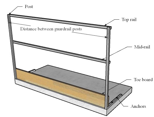
According to the Technical Recommendation of Procedures, measures to protect against falls from height, known as RTP 01 [10], guardrails are structures designed to protect against the risk of workers falling and the impact of materials and tools. A guardrail-type Periphery Protection System consists of a set of elements, such as posts, top rail, mid-rail, toe board, and anchors [25], as shown in Fig. (1).
These systems are designed to be dimensioned based on criteria as specified in regulations. In addition to Australian and Brazilian standards, the most referenced standards worldwide are described below.
2.1. Brazilian Regulation
A guardrail is characterized as a construction element designed to protect people against accidental fall risks without preventing their forced or voluntary passage [25]. In Brazil, the standard NR 18–Work Conditions and Environment in the Construction Industry guides occupational safety in civil construction. Regarding the use of temporary guardrails, it determines that the protection should be built with a minimum height of 120 cm for the top rail, the mid-rail should be installed at a height of 70 cm, the system should contain a skirting board with a height of 20 cm, and the gaps should be covered by a screen [9].
Also related to the protection used against falls in Brazil, NR 35 (on work at height) defines that all work done above a height of 2 m and containing a fall risk is considered work at height, and safety measures should be adopted. Brazilian NR 35 does not define the procedures, but it determines the hierarchy of work planning [4].
As shown, Brazilian NR 18 and Brazilian NR 35 are restricted to applying measures that should be implemented in the execution of work, and they list the items that are needed, but they do not provide information on the system's performance [9, 4].
Brazilian RTP 01, drafted by Fundacentro to support businesses, professionals, government, and workers in compliance with Brazilian NR 18, established that the top rail of the guardrail system should be made of a material with a minimum concentrated stress strength of 1500 N/m linear meter in the center of the gap. It also established that the mid-rail should have the same characteristics and strength as the top rail [10], but it fails to consider how the loads should be applied and the limits or tolerances to be followed.
2.2. United States of America
In the United States of America, OSHA 1926.502 [3] considers any work situation above 180 cm as work at height. In this case, employers are required to provide fall protection. A vertical height of 110 ± 8 cm is defined for the guardrail structure, with the mid-rail installed at approximately half-height and with toe boards of a minimum height of 9 cm. All other added structural elements may not allow openings larger than 50 cm [3].
Regarding their strength, the structures must withstand, without breaking, a force of 890 N applied at 5.1 cm of the top rail, in either direction, horizontal or vertical. Intermediate closing elements and equivalent structural elements should withstand, without breaking, a force of 666 N applied in any direction, and the skirting boards should have a minimum strength of 222 N [3].
2.3. European Union's
The European Union's standard DIN EN 13374 - Temporary Edge Protection Systems - Product Specification - Test Methods defines three classes of guard rails (A, B, and C) according to the load and the intended use [6].
Class A provides resistance only to static loads and protects working platforms with or without tilt. Class B also resists dynamic and static loads in the case of a worker who is running and falls on an inclined surface. Class C is designed to provide resistance to high dynamic forces based on the safety requirements to prevent workers from falling from steep sloping surfaces [6].
Concerning the geometry, the minimum height between the work surface and the top rail must be at least 100 cm, with the spacing between the rails and the work surface not exceeding 47 cm and with any gaps not exceeding 12 cm [6].
Regarding the loads to be used in testing, EN 13374 established the serviceability limit state, ultimate limit state, and accidental loads that the structure should withstand, as well as how the static loads should be applied in each case of the structure, with static and dynamic load testing as shown in Baruffi [26].
2.4. Quebec Safety Code for the Construction Industry
For Canada, the Quebec Safety Code for the Construction Industry (S-2.1) provides that guardrails and protective measures should be installed whenever work is done with fall risks. The guardrails must withstand a concentrated horizontal load of 900 N and a concentrated vertical load of 450 N applied at any point in the top rail [5].
Regarding geometry, the code recommends that the height of the guardrails must be between 100 cm and 120 cm above the work level. If the material used is wood, the section of the top bar and guardrail posts must be at least 4 cm x 9 cm with the guardrail posts being spaced at a maximum distance of 180 cm, the mid-rail should be at least 4 cm x 7.5 cm, and the toe boards should be at least 9 cm in height, both fixed internally to the guardrail posts. If the material is made of steel, the guardrails must have a strength equal to or higher than that required for wooden systems [5].
2.5. Australia and New Zealand
The standard for edge protection systems in Australia and New Zealand is described in AS/NZS 4994. Regarding guardrail geometry, AS/NZS 4994.1 established that the skirting boards should have a height of more than 15 cm and sufficient strength and stiffness to prevent a person from breaking through the skirting board [7].
Regarding the minimum height, AS/NZS 4994.2 recommends that it be greater than 90 cm from the floor of the slab, installed at 30 cm from the edge. The distance between the guardrail beams must be less than 45 cm, and the distance between the toe board and mid-rail should be less than 27.5 cm [8].
The guardrail posts and beams should withstand a static load of greater than 600 N, applied at any point and any direction. The maximum deformation, both in the posts and beams, must be less than 10.1 cm. For dynamic loads, AS/NZS 4994.1 also specifies a test to be used in guardrail structures [7].
2.6. Comparison Between Standards
Table 1 presents a comparison of the different Brazilian standards (NR 18, NR 35, and RTP 01), the standards of the United States (OSHA 1910.26.502), the European Union (13374:2013), Canada (Quebec S-2.1 r.4), Australia and New Zealand (AS/NZS 4994), and compares the geometry and strength requirements found in each standard.
It is observed that the greatest divergences between the standards concern the application of a load of 1500 N/m in RTP 01 [10], compared to 900 N in OSHA 1023.10 [3]. For EN13374 [6], an entire calculation method is standardized with loads for the service limit state (ELS), ultimate limit state (ELU), and accidental loads for each constituent of the guardrail; the Canadian standard has a minimum resistance for the crossbar of a horizontal load of 900 N and vertical of 450 N [5], and the AS/NZS standard 4994 specifies 600 N applied at any point and in any direction of the structure [7]. Regarding the geometric requirements, the guidelines vary between a height of 90 cm according to AS/NZS 4994 [8] guidelines, and 120 cm according to the NR 18 and Québec codes [9, 5].
3. EXPERIMENTAL STATIC AND DYNAMIC TESTS OF PROVISIONAL GUARDRAIL STRUCTURES
The experiments were carried out using guardrails of two materials: steel and wood. The loads were analyzed statically and dynamically to verify the strength of the installed structures.
3.1. Equipment
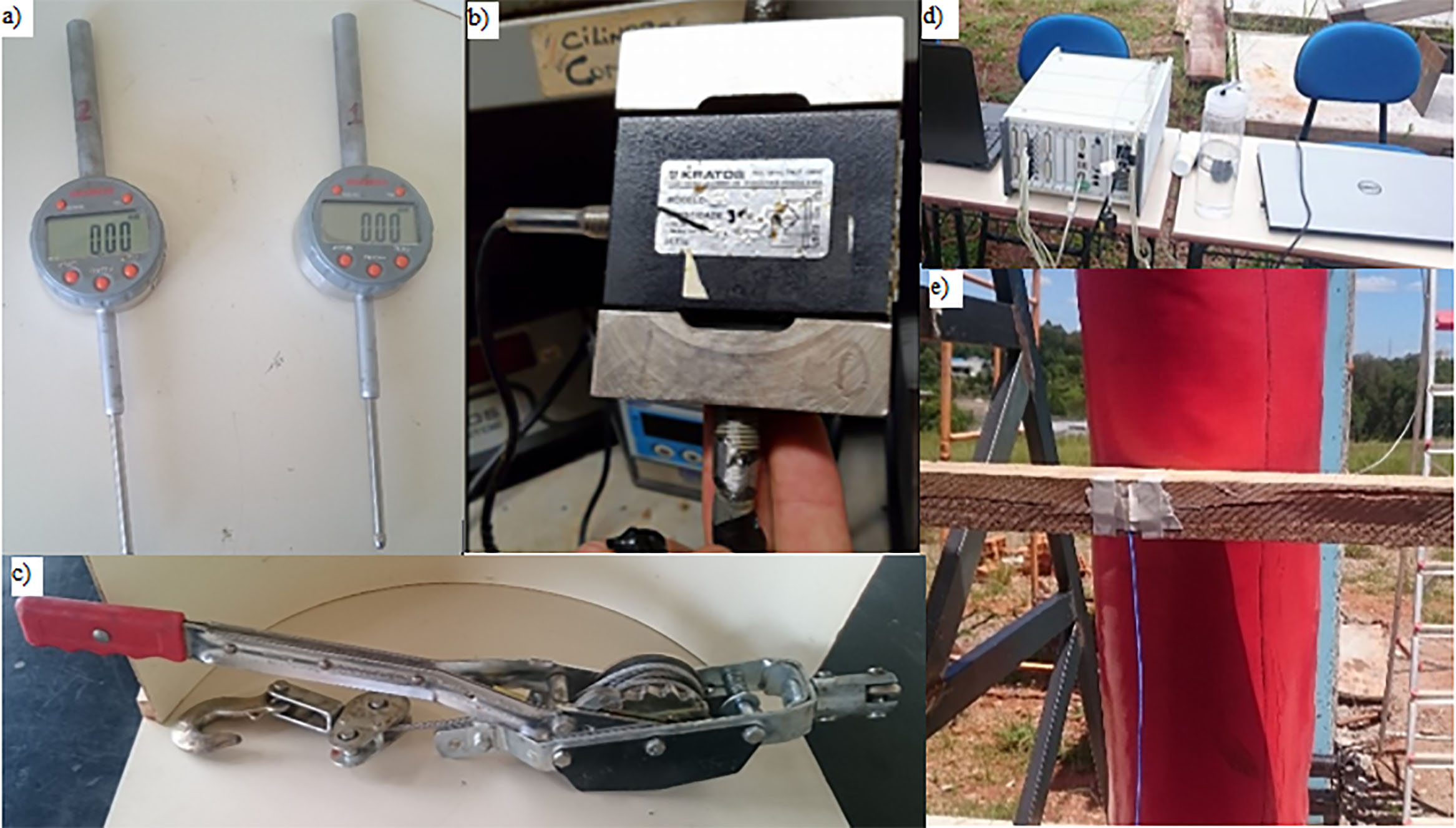
The following equipment was used in Fig. (2).
a) Dial indicators: to carry out displacement measurements of the upper and mid-rail. The indicators were of the Digimess brand, with a range of 50 mm and resolution of 0.01 mm, shown in Fig. (2a).
b) Type “S” load cell: used to measure the load applied to the structure. The load cell was of the Kratos brand, equipment model KM, with a capacity of 5000 N, shown in Fig. (2b).
c) Ratchet: installed to apply the load to the structure, shown in Fig. (2c).
d) Data acquisition system: used to measure the acceleration. The model used in the tests was MGC Plus, manufacturer HBM; the software used was Catman EASY AP version 3.5.1.48 with 8 channels used, shown in Fig. (2d).
e) Triaxial accelerometers: the accelerometers used were model 2460-010, manufactured by Silicon Designs, a capacitive type, with a sensitivity of 400 mV/g and response in the frequency range of 0 to 1000 Hz, with an acquisition range of 2400 samples per second, shown in Fig. (2e).
(a) Dial indicators; (b) Load cell; c) Ratchet; d) Data acquisition system; (e) Accelerometer sensor installed on the structure.
| Standards | Geometry | Work at Height Above: (m) | Action Applied | |||||
|---|---|---|---|---|---|---|---|---|
| Top Rail Height (m) | Mid-Rail Height (m) | Toe Board (m) | Distance Between Guardrail Posts | Section (mm) | ||||
| Material | Distance (m) | |||||||
| NR 18 [9] | 1.2 | 0.7 | 0.2 | N.A. | N.A. | N.A. | N.A. | N.A. |
| NR 35 [4] | N.A. | N.A. | N.A. | N.A. | N.A. | N.A. | 2 | N.A. |
| RTP 01 [10] | N.A. | N.A. | N.A. | Wood | 1.5 | N.A. | N.A. | 1500 (N/m) |
| OSHA 1926.502 [3] | 1.10 ± 0.08 | Gaps < 0.53 | 0.09 | Wood | 2.4 | 50x100a | 1.8 | Top rail = 890 (N) |
| 25x150b | Mid-rail = 666 (N) | |||||||
| Steel | 2.4 | 50x50x10 | Toe board = 222 (N) | |||||
| EN 13374 [6] | 1 | < 0.47 | 0.15 | N.A. | N.A. | N.A. | N.A. | See Baruffi [26]; EN 13374 [6] |
| S-2.1, r.4 [5] | 1–1.20 | N.A. | 0.09 | Wood | 1.8 | 40x90a | 3.00 or 1.2e | Horizontal = 900 (N) |
| 40x75b | Vertical = 450 (N) | |||||||
| AS/NZS 4994 [7, 8] | > 0.90 | < 0.45c | > 0.15 | N.A. | N.A. | N.A. | N.A. | Horizontal = 600 (N) |
| < 0.275d | ||||||||
| N.A. Not Available. a Top rail. b Mid-rail. c Between top and mid-rail. d Between mid-rail and toe board. e Depending on working conditions. | ||||||||
3.2. Models Tested
Three model guardrails made of steel (MOD_STEEL) and three made of wood (MOD_WOOD) were installed. The tests were performed on full size prototypes, with four posts and two beams.
The steel model, MOD_STEEL, was designed using NBR 8800 [27] and NBR 14762 [28], considering the properties of SAE 1005 steel, including the chemical composition of the material, approximate yield strength of 180 MPa, an ultimate strength of 300 MPa. Testing to determine the modulus of elasticity found a value of 188.26 GPa [26], leading to a rectangular section of 100 mm × 40 mm × 2 mm and rails of 50 mm × 30 mm × 2 mm, spaced at 1986.0 mm.
The tested timber model, MOD_WOOD, was designed by NBR 7190 [29] and contains uprights and rectangular section rails of 100 mm × 50 mm, spaced at 1500 mm, according to the recommendation of RTP 01 [10] for wooden structures. The timber can be classified as dicotyledonous/hardwood, of class C20, according to NBR 7190 [29], with the following characteristics:
- Compression parallel to grain: 20 MPa
- Shear parallel to grain: 4 MPa
- Modulus of Elasticity: 9500 MPa
The attachment of the vertical columns to the experimental track was carried out according to ASTM A36, using a steel sheet (300 mm x 280 mm x 6.3 mm) and fixed screws of the parabolt type 12.7 mm x 133 mm, sized to resist the stresses generated at the base. The concrete used for the experimental track was rated at 25 MPa, simulating the usual concrete for building slabs.
For the steel model, pins connecting the elements made of ASTM A307 steel were used. Screw connections were made for the wooden model.
Figs. (3 and 4) show the elements of the guardrail systems MOD_STEEL and MOD_WOOD, respectively, including posts, top rail, mid-rail anchoring systems, and other details.


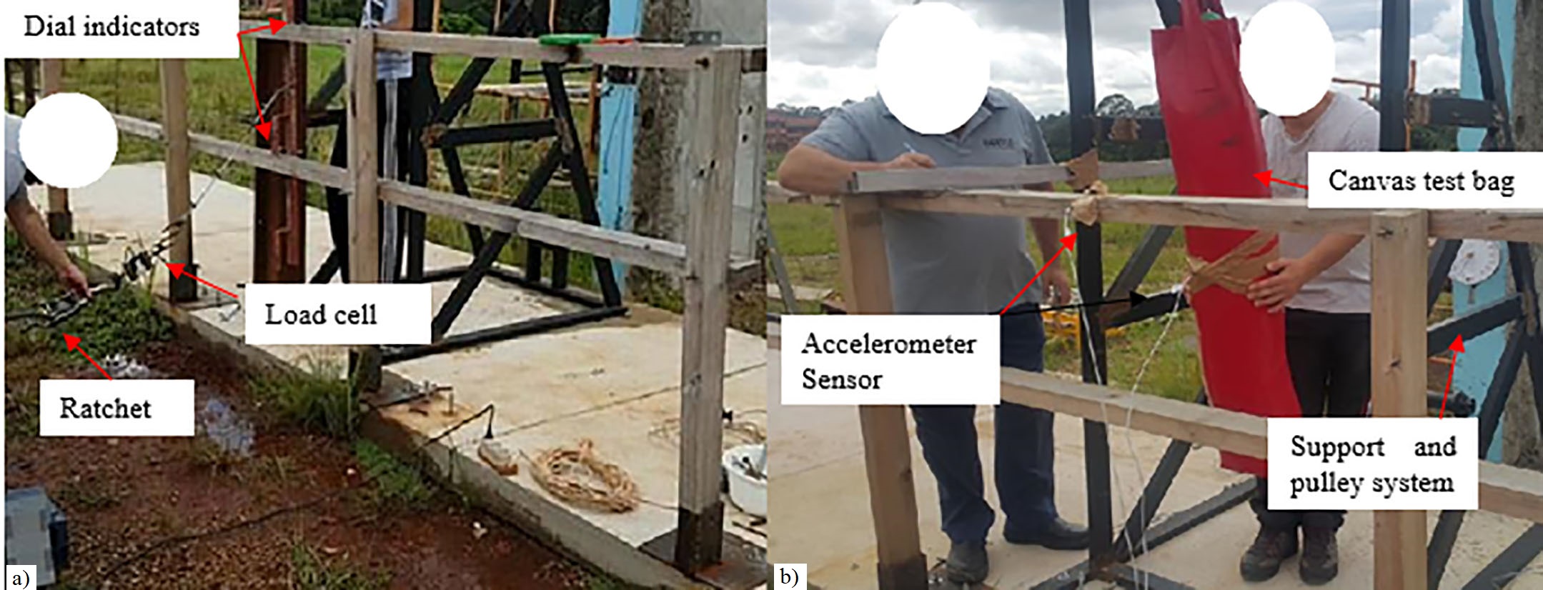
The static tests were performed by applying a load using steel support and a pulley system, in which a dial gauge measured the displacement. The dynamic tests were carried out by applying a load generated by the impact of a test bag, and the displacements in the structure were measured using accelerometers.
Fig. (5) shows the experimental setup for the static tests (a) and dynamic tests (b).
3.3. Applied Loads
The loads applied in the static tests used three values. The first, 770 N, was determined by a study carried out in the municipality of Passo Fundo / RS [26] to obtain the average mass of 38 civil construction workers using a digital scale. The second value, 1000 N, was as required by NBR 15836–Personal protective equipment against high falls–Skydiver safety, which uses a mannequin with a mass of 100 kg to test skydiver straps. This was considered to increase the measured load by the construction workers as well as the international standards already mentioned [30]. The third load value of 1500 N/m was that required by the MTE through NR 18 and RTP 01 [9, 10].
The impact load was applied with a 77.4 kg test bag, 1.5 m high and 0.25 m in diameter, filled with sand. The drop height for impact was located at a horizontal distance of 77. 52 cm and a height of 16.74 cm resulting in an impact force of approximately 127.1 J considered from the center of gravity of the test bag, with an angle formed by the pendulum of 27.33° and an approximate velocity of 1.8 m / s. Other restrictions were placed in the layout of the laboratory facility, like test frame dimensions limits.
Fattal and Cattaneo [31] developed a study to investigate guardrail systems for the Occupational Safety and Health Administration (OSHA) in which they considered that the average human walking speed was 4 km / h (1.11 m / s) and a fast walk was 7.2 km / h (2m / s). The speed reached by the test bag was, therefore, within the range between regular and fast walking speed. Also, those authors performed tests with the maximum attainable speed within the constraints of laboratory space: 5.3 km/h (1.47 m/s). In this paper, the velocity was set at approximately 1.8 m/s.
3.4. Experimental Static Guardrail Tests
The procedures for performing the static tests are described below. The required equipment was as follows:
a) Dial indicators
b) S load cell
c) Ratchet.
The dial indicators were installed to read the deformations near the center of the guardrail beams.
For MOD_STEEL, the measurements occurred at 745 mm from the guardrail posts for the dial installed on the top rail and 735 mm from the dial installed on the mid-rail. For MOD_WOOD, the measurements occurred at 535 mm from the guardrail posts where the dial was installed on the top rail and 510 mm in the mid-rail.
The load was applied horizontally to the structure with a ratchet, load cell, pulley structure, and steel bar to distribute the load between the two guardrail beams. After positioning all equipment and displacement measurement devices, the first calibration test and adjustments were performed. Next, a pre-load was applied to adjust the gaps in the structure. Subsequently, the loads to be analyzed were applied to the structure.
The initial load (770 N) was applied at the top and middle rail centers. The instantaneous displacements were recorded immediately after the application of the load and one min later. There was no variation in displacement with load application time, considering the elastic behavior of the structure. The load was then removed.
The next load applied was approximately 1000 N, and the instantaneous displacements were recorded immediately after applying the load and one min after applying the load. The load was then removed.
In addition, according to Brazilian recommendations by the NR 18 and RTP 01 [9, 10], loads of 3000 N (1500 N/m) for MOD_STEEL and 2250 N (1500 N/m) for MOD_WOOD were applied in the same way as in previous tests. Displacements were recorded on dial indicators.
3.5. Experimental Guardrail Impact Tests
The impact tests were developed by the following procedures. The required equipment was:
a) Data acquisition system;
b) Canvas test bag filled with sand weighing 77.4 kg;
c) Support and pulley system to fix the bag and apply the load as exposed.
The impact load was applied with a test bag, lifting it in a pendulum motion and releasing it so that it hit the structure only once.
Three tests were performed, and the results were measured using accelerometers. After obtaining the accelerometer readings, the acceleration information in the time domain was obtained and recorded in Excel spreadsheets using the data acquisition system. The displacements could be determined by numerical integration using the trapezoidal rule. These operations were performed in MATLAB [32].
3.6. Acceptance Criteria
The experimental results are presented according to the determinations of Brazilian NBR 14718—Guardrails for Buildings [25]. This standard refers to the acceptance criteria for permanent guardrails, which had to be considered in the absence of acceptance criteria in Brazilian standards for temporary guardrails.
According to Brazilian NBR 14718 [25], acceptance criteria vary according to the application. For static loads applied horizontally to the structure, the guardrail system should present no rupture, loosening, or detachment of components. Deformations in the application of service loads should not exceed 20 mm.
Brazilian NBR 14718 [25] only has visual requirements for impact strength, observing any damage or ruptures in the system without determining displacement values.
AS/NZS 4994.1 [7] has acceptance criteria for impact testing and visual evaluations regarding detachments and structural failure, specifying that the maximum deformations of guardrail posts and the top rail cross should be less than 401 mm. EN 13374 [6] specifies that a maximum deformation of 100 mm may occur, provided that the structure can support the impact.
4. RESULTS AND DISCUSSION
4.1. Experimental Static Guardrail Tests
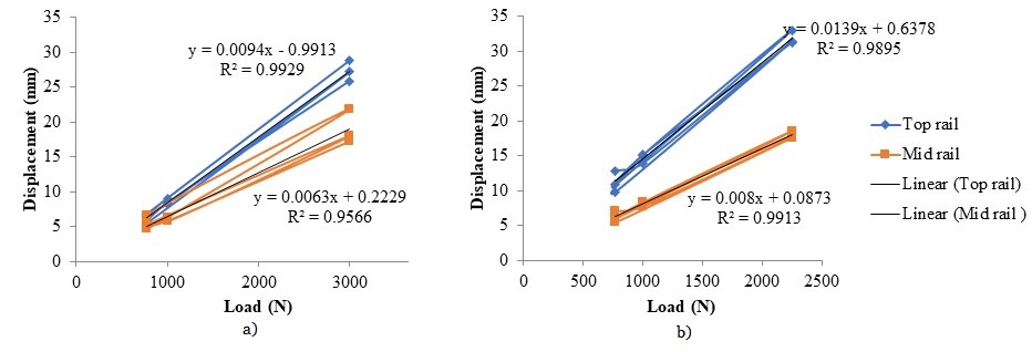
The static test shows a linear relationship of displacement to load. In the steel models, R2 = 0.9929 for the top rail and R2 = 0.9566 for the mid-rail, as shown in Fig. (6a). The wooden models also had a linear relationship, R2 = 0.9895 for the top rail, and R2 = 0.9913 for the mid rail, as shown in Fig. (6b).
This slight difference can be explained because the wood system was more rigid than the steel system with respect to the connections. For MOD_WOOD, screwed connections were made versus connections with fastening pins for MOD_STEEL, which presented gaps in these elements. The distance between the elements was smaller for MOD_WOOD (1500 mm) than the 1986.0 mm for MOD_STEEL. In addition, the stiffness of the structure indicates a greater moment of inertia in the direction of load application.
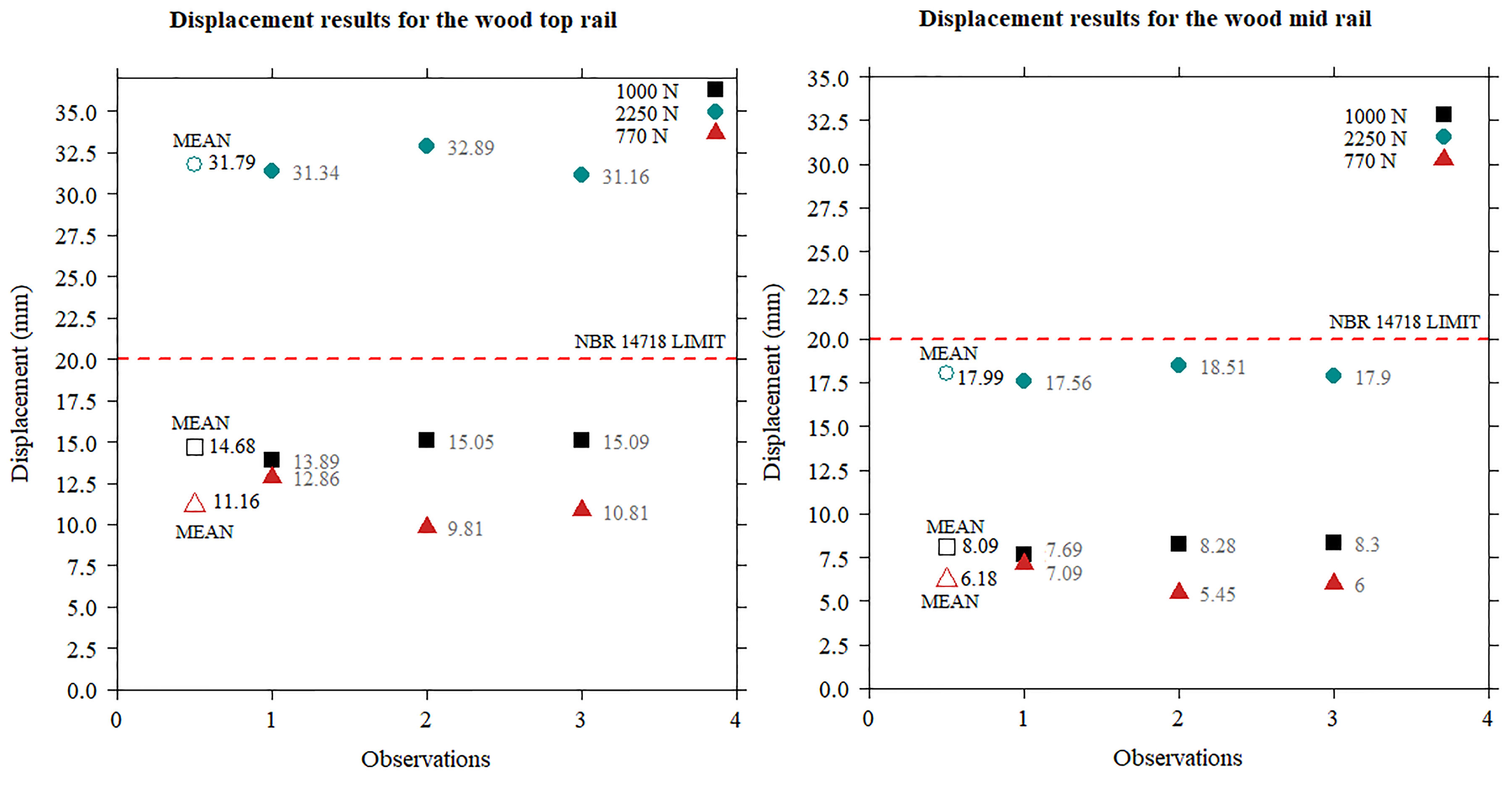
Figs. (7 and 8) show the displacement records in the experimental static test structures in comparison with the acceptance criteria for MOD_STEEL and MOD_WOOD, respectively.
The displacements from the experimental tests are compared with the recommendations of Brazilian NBR 14718 [25]. In some tests, they exceed the maximum value established by the standard.
It should be noted that the MOD_STEEL and MOD_WOOD did not comply with the application of a load of 1500 N/m to the top rail, the load required by Brazilian RTP 01 [10], because the displacement media were higher than allowed, by approximately 37% and 59%, respectively.
It was also observed that the measurement for the mid-rail in MOD_STEEL exceeded the limit of NBR 14718 [25].
4.2. Experimental Impact Tests
Fig. (9) presents the numerical integration results of the experimental impact tests using MATLAB [32]. The limit adopted was based on the European standard [6] because it is more restrictive (100 mm). The displacements of all impact tests were within limits determined by the AS/NZS 4994.1 [7] (401 mm) and EN 13374 [25] (100 mm) standards.

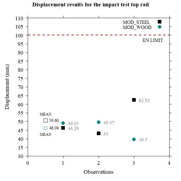
The tested guardrails were inspected after the tests, and there was no damage, which means that the structure was able to absorb the impact.
The influence of the clearances in the MOD_STEEL connections presented a more significant variation in the results than for MOD_WOOD.
5. DISCUSSION
When analyzing the displacements of the experimental tests of the static loads, it can be seen that the two models (MOD_STEEL and MOD_WOOD) do not meet the requirements of the Brazilian NBR 14718 [25] with a maximum displacement of 20 mm for a load of 1500 N/m, as required by Brazilian RTP 01 [10].
If the same analysis was performed according to the international standard EN 13374 [6], the maximum allowable displacement in the static test would be 55 mm, with 101 mm allowable displacement for AS/NZS 4994 [7]. In this case, all loads for MOD_STEEL and MOD_WOOD would meet the requirements of those standards.
Both the 770 N and 1000 N loads satisfied the displacement limits defined by NBR 14718 [25] and are within the international standards.
Brazilian NBR 14718 [25] has more demanding criteria because its scope is related to permanent guardrails in buildings. On the other hand, even though the tested guardrails did not meet the acceptance criteria, there was no visual damage to the system or its components.
When analyzing the structural behavior with the application of the impact test (127.1 J at a speed of 1.8 m/s), the designed systems were able to absorb a fall impact without any local or global collapse of the system, with displacements below the thresholds determined in international standards AS/NZS 4994.1 [7] (401 mm) and EN 13374 [6] (100 mm).
It is possible to state that the load of 1500 N/m required by RTP 01 [10] lies outside the international standards because, in the other surveyed standards, the greatest load did not exceed 900 N.
As González et al. [22] already observed regarding the test bag simulating the impact of a human body, it applies a higher load than that applied by the human body because of the lower impact absorption capacity of the test bag. Thus, it is possible to state that the structures are subjected to greater loads in experimental tests than in a real fall by a worker.
For the models tested experimentally, the two systems, MOD_STEEL and MOD_WOOD, can be used if they are correctly designed, and it is essential to verify the positioning of the greatest inertia of the element, as already pointed out by Lan and Daigle [17] and Galy and Lan [23]. The wood models behaved more linearly with respect to the differences between the materials in the tests, as wood is an orthotropic material and has a lower modulus of elasticity.
Thus, it is crucial to evaluate the connections in the systems, as already highlighted by Bobick et al. [18], in particular the importance of the correct dimensioning of screws, and the nails used for fixing the elements.
CONCLUSION
This work conducted experimental studies of guard rails as one of the elements adopted against falls from height.
The experimental study showed that the tested structures were able to absorb an impact generated by a simulation of a human body, although in the static test, the measured displacements exceeded the established acceptance criterion.
The wooden model showed better behavior than the steel model, due to its greater rigidity and execution of the connections. It is therefore essential to consider the position of the highest inertia to receive the horizontal loads and to take care care in the connection of the elements.
In addition to Brazilian standards, NR 18, NR 35, and RTP 01 vary considerably in relation to international norms, and NBR 14718, used for evaluation of permanent guard rails, is not applicable to provisional structures.
In this context, the study provides guidance for the execution of structures and support for the structures to meet the normative and safety needs of construction workers.
FUTURE SCOPE AND RECOMMENDATIONS
For future work, it is recommended to carry out tests using the usual structures of civil construction work to assess the safety provided in these places. The models used in this work were sized for loads recommended by Brazilian standards and specific standards, but they differed greatly from those used in practice.
The evaluation of residual displacements is also recommended for a better understanding of how structures behave during the tests, and examination of connections and gaps in the systems.
It is recommended that the Brazilian regulation be evaluated in order to match international standards, mainly in terms of resistance requirements and including verification methodology for temporary structures.
CONSENT FOR PUBLICATION
Not applicable.
AVAILABILITY OF DATA AND MATERIALS
Not applicable.
FUNDING
None.
CONFLICT OF INTEREST
The authors declare no conflict of interest, financial or otherwise.
ACKNOWLEDGEMENTS
Declared none.

