All published articles of this journal are available on ScienceDirect.

Progressive Collapse Performance of Steel Beam-to-Column Connections: Critical Review of Experimental Results
Abstract
Background:
The steel beam-to-column connections are vulnerable structural elements when a building loses one or more of its vertical load-carrying components due to abnormal or accidental loading conditions. After a column is destroyed by abnormal loads, the tensile axial force of the beam gradually increased, while the bending moment decreased, and the load-resistance mechanism shifts from a flexural mechanism to a catenary mechanism, with the axial force becoming the prevailing factor.
Aims:
This paper investigates the progressive collapse performance of steel beam-to-column connections. While undergoing large deformation, the beam-to-column connections are subjected to moment, shear, and tension in conjunction with high ductility demand. Their behavior under monotonic loading depends on the moment-axial tension interaction and greatly affects the progressive collapse resistance of the structure. This paper presents a critical review of experimental tests of different types of steel beam-column joints (flexible, rigid, and semi-rigid) under a central-column-removal scenario.
Methods:
The experimental results, including load-deformation relationships, failure modes, and catenary effects, are described in detail. The findings are used to evaluate the rotation capacity of different types of steel beam-to-column connections. The results are compared to the acceptance criteria specified by the main progressive collapse guidelines for several beam-to-column connection categories.
Results:
In simple (flexible) joints, the stiffness and strength at higher drift angles essentially depend on the tensile capacity of the connection that prevents, in some cases, the full development of the catenary mechanism. The connection depth alone does not seem to be an effective parameter to predict the rotational capacity of beam-to-column connections, since different connections with similar values of the connection depth result in very different values of the maximum rotation capacity. In fully rigid and semi-rigid connections, after the column removal, the flexural resistance controls the behavior at the preliminary phase, and the tensile force is almost zero. With increased downward displacement, the axial tensile force also increases, developing a catenary mechanism. Although the stiffness of rigid and semi-rigid connections is higher than flexible connections, both categories result in similar rotation capacity.
Conclusion:
In all the simple connections herein considered, the plastic rotation capacity obtained by tests was found much higher than the code recommended values that are probably too conservative. On the contrary, for one rigid and two semi-rigid connections, the values of the plastic rotation capacity obtained by tests are lower than the corresponding recommended values. Thus, the suggested acceptance criteria proved to be out of the conservative side.
1. INTRODUCTION
1.1. Background
A series of disasters owing to abnormal or accidental loading conditions (i.e., impact, fire, blast, collision, gas explosion, landslides, floods, and so on) that occurred around the world have highlighted the poor performance of certain structural typologies and, in general, the extreme vulnerability of strategic and critical infrastructure to abnormal loads. Therefore, over the last decade, great effort has been made to investigate the progressive collapse resistance of structures [1-9]. Due to these unforeseen hazards not explicitly considered in the design, the structure can be at risk of initial local damage that can result in a spread of failure to surrounding members and, eventually, lead to the collapse of or a disproportionately large part of the structure, known as progressive collapse. In place of calculations demonstrating the effects of abnormal loads on buildings, the existing guidelines make use of the alternate path approach to determine the susceptibility to progressive collapse. This approach presumes that one critical member (typically vertical load-carrying columns or bearing walls) is removed because incapable of supporting the load and the remaining structure must be able to span across the removed member. After a column is destroyed by abnormal loads, different mechanisms are mobilized to transfer the gravity loads on superstructures and avoid collapse: Vierendel action, catenary action, columns acting as suspension, compressive arching in beams, membrane action in slabs. The “catenary action” refers to the ability of beams to resist the vertical loads by developing a string-like mechanism under large displacements and rotations [10-14]. After column removal, a new equilibrium is found by redistributing the internal forces of the remaining structure. Initially, the beams adjacent to the removed column tend to resist the vertical load by the generation of a bending moment. However, with increasing vertical displacement (i.e., in the large deformation stage) the gravity loads are mainly resisted by the vertical components of the axial forces that develop in the beams (i.e., catenary forces). This so-called “catenary action” generates a supplemental resistance that prevents progressive collapse of the structure. Practically, the load-carrying mechanism changes from plastic hinge action to tensile catenary action. However, its activation depends on the geometrical nonlinear behavior of the structure. At first, the structure should be ductile enough to allow large inelastic deformations and make possible the transition from the flexural resistance to the tensile catenary resistance. Then, the constraints of the beam end provided by the side columns should give a sufficient lateral anchorage to these catenary actions. Finally, the beam-to-column connections should be able to transfer the increased axial force in the beams due to the catenary action.
1.2. Beam-to-column Connections Subjected to a Sudden Column Removal Scenario
After the removal of a critical vertical load-bearing element (typically a column), an alternative load path should be provided. In this scenario, the connections of steel moment-resisting frames (MRFs) play a critical role since an alternative load path can be mobilized only if the beam-column connections have enough rotational capacity to sustain the abnormal extra-loads following the column removal. Usually, the beam-to-column joints of moment-resisting frames are designed to withstand gravity and seismic loads. However, the internal actions on these connections resulting from the sudden column removal differ significantly from those under earthquake loading. First, the connections are loaded cyclically under earthquake ground motions, while the column removal results in monotonic loading. Then, the beam-to-column joints are subjected primarily to bending under seismic loading, while they are subjected to bending and axial force under column removal scenarios. After a specific value of rotation, a considerable tensile axial force occurs in the beam and connections due to the development of catenary action, thus making its behavior very different from the seismic situation. This tensile axial force significantly reduces the moment capacity of the connection. Consequently, even moment frames appropriately designed for seismic loads may not resist progressive collapse since a significant axial force can develop in the connections. Thus, the behavior of the beam-to-column joints undergoing large deformation should be properly studied since moment, shear, and tension, in conjunction with high ductility demand, simultaneously occur. The connections should be ductile enough to sustain significant deformation while maintaining sufficient integrity to develop catenary forces. Only in this case, the catenary action can give an alternate load path after the flexural strength is reached and the flexural failure begins. The catenary action can provide considerable resistance depending on different factors: adequate vertical displacement to produce a significant vertical component in the axial force, high lateral restraint provided by the adjacent structures, and subsequent high tensile axial forces in beams and connections. Therefore, the performance of beams and beam-to-column connections plays an important role in the activation and development of catenary action under large deformations [15, 16]. The nonlinear behavior of connections in steel frames depends on many parameters, including the performance of steel material, slips, local inelastic deformations, and fractures in bolts, weldings, flanges, and so on. In the past, a great effort was made to evaluate the effect of the catenary action in increasing the progressive collapse resistance of steel frames [17, 18]. However, many studies in the literature have been dedicated to the performance of beam-to-column connections under pure bending [2-4, 6-9, 12-14], thus neglecting the negative effect of the tensile axial force in connections due to the catenary action. However, under critical column removal scenarios, the steel connections are subjected to bending moment combined with the tensile force due to the large vertical displacement. Thus, in recent years many experimental studies have been developed to study the dual effect of axial tension in beam-to-column connections and its impact on the progressive collapse resistance including the catenary effect [19-38]. Nevertheless, most existing analytical models for beam assemblies under a progressive collapse scenario essentially assume that the plastic strength remains available despite very large deformation [39]. Consequently, the strength degradation due to local failure is neglected and, thus, the effect of catenary action on the resistance can be largely overestimated.
1.3. Objective
The experimental studies available in the literature have shown that different beam-to-column joints have different performances under a column removal scenario, as far as both the progressive collapse resistance and the catenary mechanism. Therefore, it seems necessary to develop a database of full-scale test results on double-span assemblies. This paper tries to overcome this gap by presenting a critical review of experimental tests of different types of beam-to-column connections under bending and axial tension due to column removal. To this aim, fully rigid, semi-rigid, and flexible connections are investigated. Their load-displacement response both in flexural and catenary action stages are described and commented on below. The resistance and rotational capacities of beam-column joints are investigated, and their effect on the activation and extend of catenary action is evaluated. The failure modes under sudden column loss as determined experimentally are discussed in detail. The test results are finally used to evaluate the rotation capacity of several steel subassemblies. The values obtained are finally compared to the acceptance criteria specified by the main progressive collapse guidelines for several beam-to-column connection categories.
2. PROGRESSIVE COLLAPSE BEHAVIOR OF MOMENT FRAME CONNECTIONS
2.1. Code Requirements
The Northridge earthquake in 1994 and the Kobe earthquake in 1995 revealed the brittle failure of beam-to-column connections, thus generating alarm about the reliability of the seismic codes where the ductility of beam-to-column connections is essential for the steel moment frames to be considered highly ductile. In the same way, the collapse of the World Trade Center produced concern about the design against abnormal loads, thus stimulating the development of standards and design guidelines to resist progressive collapse [40-43]. The beam–to–column connections play a critical role in progressive collapse resistance of steel frames since the rotation capacity of joints usually controls the activation of the catenary action. The corresponding acceptance criteria were defined using both tests results and numerical simulations available in the literature. In the 2005 version of UFC 4-023-03 [40] the rotational capacity values for connections were based on the 2003 version of GSA [42] and reasonably agreed with those in ASCE 41 [44]. However, the ASCE 41 acceptance criteria were based on experimental tests of beam-to-column connections under cyclic loads, where the rotational capacity is limited by degradation and loss of strength due to low cycle fatigue. On the contrary, in the experimental tests under a central-column-removal scenario, the beam-to-column connections are subjected to monotonic loads and significant axial tension forces. Therefore, significant performance differences were found, due to the effects of loading (monotonic vs. cyclic) and the ultimate state (moment-axial tension interaction vs. moment only). As a consequence, the modeling and acceptance criteria in the 2016 version of UFC [41] and GSA [43] were defined based on a comparison between the deformation limits contained in various documents and guidelines, such as ASCE 41 [44], Eurocode 3 [45], 2005 UFC 4-023-03 [40] and GSA Test Program [46]. Nevertheless, it seems necessary to develop an extended database of test results since different beam-to-column connections show significant behavioral differences, especially in the catenary mechanism.
2.2. Experimental Tests
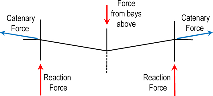
After column removal, a “double-span” scenario arises, and the performance of the affected moment connections plays a central role in the progressive collapse resistance. Therefore, the experimental tests are performed on double-span assemblies comprising two adjacent beams connected by a failure column at the center (Fig. 1). In this situation, the moment connections are the weakest components, thus affecting the anti-collapse resisting capacity of the beam–to–column assemblies. Among them, the simple connections, which are nominally pinned connections, are very popular due to their simplicity and, thus, they’re widely used both in non-seismically designed steel frame structures and in the gravity frames of seismically designed steel buildings. However, previous research papers highlighted that the simple connections are very vulnerable to progressive collapse, even if they’re designed to meet the tie-force requirements of building codes [18, 19, 47-49]. If large rotations are not explicitly accounted for in the design stage, the simple connections can fail before the development of tensile catenary action because of the large ductility demand [10, 50]. On the other side, the progressive collapse performance of fully rigid and semi-rigid beam-to-column connections is very sensitive to the tensile axial force in the connected beams since the catenary action is the fundamental mechanism to resist vertical loads in the large deformation stage. This is the reason why many types of beam-to-column connections have been experimentally investigated, including simple, rigid, and semi-rigid connections. In the next section, since beam-to-column connections play a critical role in progressive collapse resistance of steel structures due to the catenary mechanism, the performance of different beam-to-column connections against progressive collapse is investigated using available full-scale tests results on double-span assemblies.
2.3. Simple (Flexible) Connections
In this section are summarized the experimental tests on simple (flexible) steel beam-column connections available in the literature. Table 1 shows the details about the experimental tests herein considered, including reference, connection type, specimen, span-to-depth ratio, and failure mode. The beam-to-column connection types herein considered are 1-14) bolted-angle connections tested by Yang & Tan [20]; 15-18) web cleat, top and seat angle, top and seat with web angle (TWSA), and fin plate connections tested by Yang & Tan [21]; 19) web cleat connection tested by Liu et al. [22]; 20) double web angle tested by Zhong et al. [23]; 21) shear-connection tested by Alrubaidi et al. [24]. Yang & Tan [20] experimentally investigated bolted-angle connections under tension, considering fourteen specimens by varying some important parameters such as material properties, bolt size, angle thickness, and bolt hole positions. Depending on the strength ratio between angles and bolts, five different types of failure modes were observed during the tests (i.e., angle fracture at bolt holes, angle fracture at bolt holes with yielded bolts, angle fracture close to heel, angle fracture close to heel with yielded bolts and bolt fracture with yielded angles). The test results show that the load-displacement responses of bolted-angle connections were dominated by the response at the large deformation stage rather than at the small deformation stage . Therefore, the ultimate strength of connections is much greater than the yield strength. Yang & Tan [21] carried out experimental tests on simple connections including web cleat, top and seat angle, top and seat with web angle (TSWA) (8 mm thickness angles), and fin plate connections. They investigated the failure modes of these connections and their abilities to deform in the catenary mode. The test results show that the tensile capacity of the beam-to-column connection controls the failure mode and the mobilization of catenary action. For web cleat and fin plate connections, the behavior is dominated by catenary action since the applied load increases significantly only at the large deformation stage. The web cleat connection has the best performance in the development of catenary action if compared to the other connections. For top and seat angle connections, the behavior is governed by the flexural action with a little load contribution from the catenary action. Finally, the rotation capacities of beam-to-column connections based on the experimental results were found much higher than the values recommended by UFC [41] and GSA [43].
Liu et al. [22] developed experimental tests and numerical analyses to investigate the dynamic behavior of web cleat beam-column connections subjected to a sudden column removal scenario. Test results showed that the maximum displacement of the web cleat connections under sudden column removal would be significantly increased compared with the one under static loading conditions. The dynamic response of the connections (defined as the relationship between the initial support force of the middle column and the maximum dynamic displacement) was also investigated. The analysis results showed that the maximum dynamic load capacity of this web cleat connection was about 2.8 times lower than its static load capacity. Zhong et al. [23] developed experimental tests to study the mechanical behavior and load-deformation response of a double web angle connection (DWA). The failure of the specimen occurs for the fracture of the double web angles at the bolt hole. The behavior is dominated by the catenary action since the resistance of the specimen is mainly provided by this effect. Alrubaidi et al. [24] investigated the progressive collapse risk of three one-third scale single-story, two-bay steel frames under a column removal scenario, also considering a shear-connection (S-C) specimen. The shear connection showed a very high progressive collapse risk since the beams are unable to redistribute the load carried by the removed column to the adjacent members.
| S.No | References | Connection Type | Specimen | Span-to-Depth Ratio | Failure Mode |
| 1 | Yang & Tan [20] | Bolted-angle | A90-8-50-I | 7.9 | Angle fracture at bolt holes |
| 2 | Yang & Tan [20] | Bolted-angle | A90-8-60-I | 7.9 | Angle fracture at bolt holes |
| 3 | Yang & Tan [20] | Bolted-angle | A90-8-40-I | 7.9 | Angle fracture at bolt holes with yielded bolts |
| 4 | Yang & Tan [20] | Bolted-angle | A90-9-50-II | 7.9 | Angle fracture at bolt holes with yielded bolts |
| 5 | Yang & Tan [20] | Bolted-angle | A90-9-50-III | 7.9 | Angle fracture close to heel |
| 6 | Yang & Tan [20] | Bolted-angle | A90-9-60-III | 7.9 | Angle fracture close to heel |
| 7 | Yang & Tan [20] | Bolted-angle | A90-9-40-III | 7.9 | Angle fracture close to heel with yielded bolts |
| 8 | Yang & Tan [20] | Bolted-angle | A90-10-50-IV | 7.9 | Bolt fracture with yielded angles |
| 9 | Yang & Tan [20] | Bolted-angle | A90-10-60-IV | 7.9 | Angle fracture close to heel with yielded bolts |
| 10 | Yang & Tan [20] | Bolted-angle | B150-90-11-50-V | 7.9 | Angle fracture close to heel with yielded bolts |
| 11 | Yang & Tan [20] | Bolted-angle | B150-90-11-60-V | 7.9 | Angle fracture close to heel with yielded bolts |
| 12 | Yang & Tan [20] | Bolted-angle | B150-90-11-40-V | 7.9 | Angle fracture close to heel with yielded bolts |
| 13 | Yang & Tan [20] | Bolted-angle | C125-11-75-VI | 7.9 | Angle fracture close to heel |
| 14 | Yang & Tan [20] | Bolted-angle | C125-11-60-VI | 7.9 | Angle fracture close to heel |
| 15 | Yang & Tan [21] | Web Cleat | Specimen 1 | 7.62 | Angle fracture |
| 16 | Yang & Tan [21] | Top and seat angle | Specimen 2 | 7.62 | Angle fracture |
| 17 | Yang & Tan [21] | TSWA (8 mm angle) | Specimen 3 | 7.62 | Angle fracture |
| 18 | Yang & Tan [21] | Fin plate | Specimen 4 | 7.62 | Bolt fracture in shear |
| 19 | Liu et al. [22] | Web Cleat | WFA | 7.9 | Fracture of the web angle |
| 20 | Zhong et al. [23] | Double Web Angle | DWA | 10 | Fracture of angles |
| 21 | Alrubaidi et al. [24] | Shear-connection | S-C | 10 | Fracture of tab plate |
2.4. Rigid Connections
This section summarizes the experimental tests on rigid steel beam-column connections available in the literature. Table 2 shows the details of the experimental tests herein considered, including reference, connection type, specimen, span-to-depth ratio, and failure mode. The beam-to-column connection types herein considered are: 1-2) Beam-to-tubular column moment connections tested by Li et al. [25] (N.1 welded flange, welded web (CO-W); N.2 welded flange, bolted web (CO-WB)); 3-4) welded unreinforced flange, bolted web (WUF-B) and reduced beam section (RBS) connections tested by Lew et al. [26]; 5-6) welded unreinforced flange-bolted web connections (SI-WB) tested by Li et al. [27]; 7-9) welded flange-weld web connection (I-W), welded flange-bolted web connection (I-WB) and welded flange-bolted web connection with shear diaphragm (ST-WB) tested by Wang et al. [28]; 10) welded unreinforced flange-welded web connection (WUF) tested by Zhong et al. [23]; 11-12) welded cover plate flange connection (CWP) and haunch end plate bolted connection (EPH) tested by Dinu et al. [29]; 13-15) welded unreinforced flange-bolted web connections (WUF) tested by Meng et al. [30]; 16) bolted flange plate connection (BFP) tested by Wang et al. [31]; 17) SidePlate moment connection tested by Faridmehr et al. [32]. Li et al. [25] presented two full-scale laboratory tests on steel beam-to-tubular column moment connections with outer-diaphragm, a welded flange-bolted web connection (Specimen CO-WB), and a welded flange-welded web connection (Specimen CO-W). The specimens exhibited the same typical flexural behavior at the early stage, while exhibited two different modes of response after the fracture of the bottom flanges. For the specimen CO-W, the crack propagated deep into the web plate, thus causing a catastrophic reduction of the effective beam section. For the specimen CO-WB, the fracture at the bottom flange was interrupted from propagating into the web plate by the presence of the bolts. Thus the catenary action was developed following the flexural failure. Lew et al. [26] tested two full-scale steel beam-column connections, namely a welded unreinforced flange bolted web (WUF-B) connection and a reduced beam section (RBS) connection. The beam-column connections show an initial elastic response dominated by flexure. Then, the connections yield with increasing the vertical displacement, and tensile axial forces develop in the beams, indicating the catenary action until the connections fail under the combined bending and axial stresses. The rotational capacities were approximately twice as large as those based on seismic test data. Li et al. [27] investigated the catenary behavior of two full-scale beam-to-column assemblies, with typical H-beam and square-column moment connections with a welded unreinforced flange-bolted web connection (i.e. WUF-B connection). The results showed that both specimens were able to develop an effective catenary action via the bolted web following the primary flexural phase. The failure modes depend on the bolt arrangement. When the bolts were arranged in two rows, the shear tab cracked at the section across the bolt hole, and this makes the connection less robust. Wang et al. [28] investigated three connection types including flange-weld web connection with internal diaphragms (specimen I-W), welded flange-bolted web connection with internal diaphragms (specimen I-WB), and welded flange-bolted web connection with short through diaphragms (specimen ST-WB). The test results showed satisfactory ductility supply and load resistance of the three specimens. The lowest ductility against the initial fracture was exhibited by the specimen ST-WB due to nonsymmetrical stress distribution over the width of the beam flange. Remarkable catenary action was developed by I-WB and ST-WB specimens, while specimen I-W showed a marginal catenary action due to quick propagation of the crack over the entire beam section. Zhong et al. [23] conducted experimental tests on a welded unreinforced flange-bolted web connection (WUF specimen). The WUF connection experienced a flexural mechanism phase, a flexure–catenary mixed mechanism phase, and finally a catenary mechanism phase. The failure of the specimen occurs for the fracture of the tension flanges of the beam. Dinu et al. [29] investigated two rigid connection types designed to meet the seismic design requirements for special moment-resisting frame connections, namely, the welded cover plate flange connection (CWP) and the haunch end plate bolted connection (EPH). The specimens showed a large catenary response and both failed in the connection, owing to the combined effects of the flexural and tensile actions. The CWP and EPH connections showed ultimate rotations (i.e., 0.193 rad for the CWP specimen and 0.130 rad for the EPH specimen) greater than the acceptance criteria of UFC [41] with a significant contribution of catenary action to the ultimate load resistance. Meng et al. [30] tested three types of specimens with different span ratios (1:0.6, 1:1.0, and 1:1.4), realized using welded unreinforced flange-bolted web connections. The load-displacement curves show multiple peak loads since the local failure occurred several times in the connection zone, due to the initial fracture of the tension flange connection to the failure column, followed by the fracture of the tension flange of the beam's connection to the corresponding side column. Wang et al. [31] investigated the progressive collapse behavior of various bolted flange plate (BFP) connections. In the early stage of the test, the resistance of the frame was mainly offered by the flexural action. When the first peak load was achieved, the flexural resistance decreases as an effect of compressive arch action. Then, the tensile axial force of the beam gradually increased while the bending moment decreased, and the load-resistance mechanism shifts from the flexural mechanism to the catenary mechanism. The failure in the catenary stage was controlled by the tension fracture of the net section of flange plates or shear tab. Faridmehr et al. [32] tested the anti-collapse behavior of double-span assemblies with a fully rigid connection known as Side Plate moment connection (welded flange-welded web) using a model scaled down to 1/6th of the real size. The experimental results show that the SidePlate moment connection reached significantly high load and rotational capacities developing full catenary action. The failure mode is controlled by the tensile resistance of the beam-column joint after undergoing large rotations.
| S.No | References | Connection Type | Specimen | Span-to-Depth Ratio | Failure Mode |
| 1 | Li at al. [25] | Beam-to-tubular column moment. Welded flange-welded web connection | CO-W | 7.5 | Local buckling of top flanges Bottom flange fractured |
| 2 | Li at al. [25] | Beam-to-tubular column moment. Welded flange-bolted web connection | CO-WB | 7.5 | Local buckling of top flanges Bottom flange fractured |
| 3 | Lew et al. [26] | Welded unreinforced flange, bolted web |
WUF-B | 29.5 | Shear failure of bolts |
| 4 | Lew et al. [26] | Reduced beam section | RBS | 24.9 | Fracture of the bottom flange |
| 5 | Li et al. [27] | Welded Unreinforced Flange-Bolted Web | SI-WB | 15 | Bottom flange fractured |
| 6 | Li et al. [27] | Welded Unreinforced Flange-Bolted Web | SI-WB-2 | 15 | Bottom flange fractured |
| 7 | Wang et al. [28] | Welded Flange-Weld Web Connection | I-W | 7.5 | Bottom flange and beam web fractured |
| 8 | Wang et al. [28] | Welded Flange-Bolted Web | I-WB | 7.5 | Fracture of bottom flange and Fracture of shear plate |
| 9 | Wang et al. [28] | Welded Flange-Bolted Web Connection with Shear Diaphragm | ST-WB | 7.5 | Fracture of bottom flange and Fracture of shear plate |
| 10 | Zhong et al. [23] | Welded Unreinforced Flange-Welded Web | WUF | 10 | Fracture of the flanges |
| 11 | Dinu et al. [29] | Welded cover plate flange connection | CWP | 13.63 | Fracture in bottom cover plate |
| 12 | Dinu et al. [29] | Haunch end plate bolted connection |
EPH | 13.63 | Bolt fracture |
| 13 | Meng et al. [30] | Welded unreinforced flange-bolted web | WUF-0.6 | Left 10 Right 6 | Fracture of the flanges |
| 14 | Meng et al. [30] | Welded unreinforced flange-bolted web | WUF-1.0 | 10 | Fracture of the flanges |
| 15 | Meng et al. [30] | Welded unreinforced flange-bolted web | WUF-1.4 | Left 10 Right 14 | Fracture of the flanges |
| 16 | Wang et al. [31] | Bolted flange plate | BFP | 20 | Fracture on the weld |
| 17 | Faridmehr et al. [32] | SidePlate | SidePlate | 7.5 | Fracture of the flanges |
2.5. Semi-rigid Connections
This section summarizes the experimental tests on semi-rigid steel beam-column connections. Table 3 shows the details of the experimental tests, including reference, connection type, specimen, span-to-depth ratio, and failure mode. The beam-to-column connection types herein considered are: 1-2) welded unreinforced flange-fillet welded web connection (WUF-FW) and bolted unstiffened extended end-plate with pre-tensioned high-strength bolts connections (4 E-BUEEP-P) tested by Alrubaidi et al. [24]; 3-5) complete joint penetration (CJP) and reduced-web-section welded (RWS) connections tested by Lin et al. [33]; 6-8) flush end-plate, extended end-plate and top and seat-web angle connections tested by Yang & Tan [37]; 9) flush end-plate (EPF) connection tested by Liu et al. [34]; 10) top and seat-web angle (TSDWA) connection tested by Zhong et al. [23]; 11-12) reduced beam section welded connection (RBS) and unstiffened extended end plate bolted connection (EP) tested by Dinu et al. [29]; 13-18) flush end-plate connections tested by Gao et al. [35]. Alrubaidi et al. [24] investigated experimentally one-third scale single-story two-bay steel frame with two different steel intermediate moment frame (IMF) connections conforming to ANSI/AISC 358–16, namely a welded unreinforced flange-fillet welded web (WUF-FW specimen) and a bolted unstiffened extended end-plate with pretensioned high-strength bolts (4 E-BUEEP-P specimen). For the WUF-FW specimen, the fracture of fillet welding between the bottom flange of the beam and middle column occurs, thus preventing the mobilization of the full catenary action. For the 4 E-BUEEP-P specimen, the performance of the connection was initially controlled by flexural action, and then, with increased vertical displacement, it is dominated by the full development of the catenary action. Lin et al. [33] developed an experimental study on steel beam-column connections with complete joint penetrations (CJP) and reduced-web-section (RWS) connections with different circular web openings geometric parameters. The experimental results show that the vertical resistance was provided by flexural action in the early stages and then became catenary action as the vertical displacement increased. Two different failure modes were observed: continuous failure by the weld line fracture in CJP connection and interrupted failure in RWS connections due to the fracture of a perforated section. Yang et al. [37] presented the experimental tests of different beam-to-column connections, including flush endplate, extended end plate, and TSWA (12 mm angle) connections. The test results show that the tensile capacity of the beam-column joint, after undergoing large rotations, usually controls both the catenary action and the failure mode. The flexural action dominates the behavior of extended end plate connections since a little load contribution comes from the catenary action. On the contrary, the flush endplate and TSWA connections develop catenary action before failure. The rotation capacities of beam-column joints based on the experimental results were found much higher than the design values of UFC [41]. Liu et al. [34] conducted dynamic tests to investigate the behavior of flush endplate steel beam-column cruciform connections by using a quick-release mechanism to simulate the instantaneous removal of a column. Test results showed that the maximum dynamic displacement was significantly increased compared to the corresponding quasi-static displacement. Zhong et al. [23] investigated the progressive collapse behavior of a top-seat angle with a double web-angle connection (TSDWA). The test results show that the TSDWA connection experienced a flexural mechanism phase, a flexure–catenary mixed mechanism phase, and finally a catenary mechanism phase. The failure of the specimen occurs for the fracture of the tension angles connecting the column and beam at the bolt hole (TSDWA specimen). Dinu et al. [29] investigated the progressive collapse behavior of a reduced beam section welded connection (RBS), and an unstiffened extended end plate bolted connection (EP). The experimental results showed that the RBS specimen showed ultimate rotations greater than the acceptance criteria of UFC [41] with a significant contribution of the catenary action to the ultimate load resistance. On the contrary, the specimen EP shows the lowest ductility and ultimate load resistance, and no catenary action occurs due to the fracture of bolts in tension. Gao et al. [35] conducted a series of flush endplate semi-rigid composite joints under pure bending, pure tension, and a combination of bending moment and tension, using the specimens named SJS (sagging moment), SJSTand SJST2 (sagging moment + tensile force), SJH (Hogging moment), SJHT (Hogging moment + tensile force) and SJT (tensile force). The results from experimental tests show under pure bending moment, the semi-rigid composite joints possess sufficient rotation capacity for forming the catenary action. Under the combination of bending moment and tension, the moment capacity of the composite joint decreases linearly along with the increase of tensile force. Under tensile force, the joints tend to fail at the “catenary phase”.
3. PLASTIC ROTATION CAPACITY: EXPERIMENTAL RESULTS AND ACCEPTANCE CRITERIA
In progressive collapse tests, the rotation can occur through shear and flexural deformations in the connections. The connection rotation should be calculated relative to the rigid-body rotation of the joint. In a frame, the connection rotation is generally calculated from the chord rotation. The chord rotation is the angle between the tangent to the element axis at the considered end section and the chord connecting the end section to the point of contraflexure (i.e., the point at which the bending moment is zero). This rotation may be elastic (recoverable) or plastic (permanent). The sum of the elastic and plastic rotations gives the total connection rotation. The key parameter, both in seismic and progressive collapse assessment, is the plastic rotation angle θp, which is the inelastic (permanent) rotation that occurs after the yield rotation is reached and the entire cross-section has yielded. This is the reason why the acceptance criteria and the modeling parameters specified both in seismic (ASCE/SEI 41-13 [44], FEMA 356 [51]) and progressive collapse [40-43] guidelines are defined in terms of plastic rotation. Practically, the progressive collapse potential of the structure is made to depend on the acceptable plastic rotation angle of the connection, and failure is considered to occur when the plastic rotation angle of the connection exceeds the acceptable value. However, the current in-practice acceptance criteria of seismic guidelines [44, 51] are based on experimental tests of beam-column joints under seismic loads, which involve cyclic loading with bending moment only. In this case, the rotational capacities may be limited by degradation and premature loss of strength due to low cycle fatigue. On the contrary, under a column removal scenario, the nonlinear acceptance criteria of connections should be based on monotonic loading tests with flexural action as well as catenary action. As aforementioned, the interaction of bending and axial load may significantly limit the rotational capacity of the connections. Many beam-column joints are unable to develop significant axial tension loads upon reaching the ultimate moment capacity of the beam. On the other side, the recent progressive collapse research has demonstrated that rotational capacities for monotonic loading are most often higher than for cyclic loading. Therefore, the main progressive collapse guidelines [40-43] provide specific modeling parameters and acceptance criteria due to the performance differences related to the loading conditions, between bending moment only and moment-axial tension interaction, and between monotonic and cyclic loads (Table 4). However, it seems necessary to enlarge the database of test results, since different beam-to-column connections have different behaviors, especially in the catenary mechanism. Moreover, it’s useful to check if the acceptance criteria are conservative for progressive collapse design. Therefore, in this paper, the findings of experimental tests were used to evaluate the rotation capacities of different types of steel beam-to-column connections and compare them to the acceptance criteria of the progressive collapse guidelines [40-43]. To this aim, the experimental force-vertical displacement curve of each tested specimen was used. The vertical deflection of the column is produced by both the rigid-body rotation of the joint and the connection rotation. The connection rotation is measured through the chord rotation, using the overall deflection profile of the beams to define the point of contraflexure (i.e., the point at which the bending moment is zero). This allows for plotting the vertical load against the chord rotation. This curve is then idealized using a bilinear model, which defines the yield rotation, the plastic rotation, and the total rotation. Its value is finally compared against the allowable plastic rotation angle specified by the acceptance criteria for that connection. The value of the plastic rotation was finally compared to the allowable plastic rotation angle provided for that connection by GSA [43] (Table 4), estimated based on the depth of beam (d) and the depth of the connection (dbg). Tables 5-7 show the ultimate axial load and maximum rotation capacity of flexible, rigid, and semi-rigid connections, respectively. For flexible connections (Table 5), the maximum rotation capacity varies from 0.108 rad (fin plate, specimen 4) to 0.208 rad (S-C specimen). The test values are well beyond the recommended acceptance criteria by GSA [43] plotted in Table 4. This highlights that the tested connections exhibited a very large plastic rotation without a significant reduction in strength. Moreover, it should be observed that in Table 4 the plastic rotation capacity of partially restrained simple connections (flexible) depend only on the connection depth. However, the test results show that different connections with similar values of the connection depth result in very different values of the maximum rotation capacity. Thus, the connection depth alone doesn’t seem to be an effective parameter to predict the rotational capacity of the beam-to-column connections. For rigid connections (Table 6), the test values of rotation capacity range between 0.02206 rad (WUF specimen) and 0.193 rad (CWP specimen). For the Welded Unreinforced Flange-Welded Web (WUF) specimen, the test value (0.0678 rad) is lower than GSA value (0.0852 rad). Finally, for the semi-rigid connections (Table 7), the maximum rotation capacity varies from 0.011 rad for the SJHT specimen and 0.226 rad for the Top and Seat-Web Angle (TSDWA L = 10 mm) specimen. Two values are lower than the GSA recommended acceptance criterion: plastic rotation=0.0678 rad (GSA value=0.0852 rad) for the Welded Unreinforced Flange-Fillet Welded (WUF-FW) specimen and plastic rotation=0.011 rad (GSA value=0.013 rad) for the Flush End-Plate (SJHT hogging moment and tensile force) specimen. The results show that although the stiffness of rigid and semi-rigid connections is higher than flexible connections, both categories result in similar rotation capacity. Generally, the suggested acceptance criteria are far beyond the allowable connection rotation according to the GSA [43] standard. Therefore, the values prescribed by this standard are probably too conservative. Similar conclusions have been drawn from other studies. However, it should be highlighted that for some beam-to-column connection specimens (i.e., WUF, WUF-FW, and SJHT) the plastic rotation angles obtained from the experimental tests are lower than the allowable connection rotation, meaning that in some cases the GSA acceptance criteria are not on the conservative side.
| S.No | References | Connection Type | Specimen | Span-to-Depth Ratio | Failure Mode |
| 1 | Alrubaidi et al. [24] | Welded unreinforced flange-fillet welded web | WUF-FW | 10 | Fracture of fillet weld |
| 2 | Alrubaidi et al. [24] | Bolted unstiffened extended end-plate with pretensioned high-strength bolts |
4 E-BUEEP-P | 10 | Fracture of end plate |
| 3 | Lin et al. [33] | Complete joint penetration | CJP | 7.55 | Arc crack in beam-column interface |
| 4 | Lin et al. [33] | Reduced-web-section welded connection | RWS CD100-B140 |
7.55 | Arc crack in beam-column interface |
| 5 | Lin et al. [33] | Reduced-web-section welded connection | RWS CD140-B140 |
7.55 | Fracture of perforated section Local necking in top flange |
| 6 | Yang & Tan [37] | Flush End-Plate | Flush End-Plate | 9.5 | Bolt thread stripping |
| 7 | Yang & Tan [37] | Extended End-Plate | Extended End-Plate | 9.5 | Weld fracture |
| 8 | Yang & Tan [37] | Top and Seat-Web Angle | TSWA (L = 12 mm) | 9.5 | Bolt fracture |
| 9 | Liu et al. [34] | Flush End-Plate | EPF | 9.25 | Bolt thread stripping |
| 10 | Zhong et al. [23] | Top and Seat-Web Angle | TSDWA (L = 10 mm) | 10 | Fracture of angles |
| 11 | Dinu et al. [29] | Reduced beam section welded connection | RBS | 13.63 | Fracture of top flange |
| 12 | Dinu et al. [29] | Unstiffened extended end plate bolted connection |
EP | 13.63 | Fracturing of the bolts |
| 13 | Gao et al. [35] | Flush End-Plate | SJS (sagging moment) | 7 | Bolt fracture |
| 14 | Gao et al. [35] | Flush End-Plate | SJH (hogging moment) | 7 | Welding seam fracture |
| 15 | Gao et al. [35] | Flush End-Plate | SJST (sagging moment and tensile force) | 7 | Bolt fracture and welding seam fracture |
| 16 | Gao et al. [35] | Flush End-Plate | SJST2 (sagging moment and tensile force) | 7 | Bolt fracture and welding seam fracture |
| 17 | Gao et al. [35] | Flush End-Plate | SJHT (hogging moment and tensile force) | 7 | Welding seam fracture |
| 18 | Gao et al. [35] | Flush End-Plate | SJT (tensile force) | 7 | Welding seam fracture |
| Connection Type | Nonlinear Modeling Parameters | Nonlinear Acceptance Criteria | |||
| Plastic rotation angles (rad) |
Residual strength ratio |
Plastic rotation angles (rad) | |||
| a | b | c | Primary | Secondary | |
| Fully Restrained Moment Connections | |||||
| Improved WUF with Bolted Web | 0.021 - 0.0003d | 0.050 - 0.0006d | 0.2 | 0.021 - 0.0003d | 0.050 - 0.0006d |
| Reduced Beam Section (RBS) |
0.050 - 0.0003d | 0.070 - 0.0003d | 0.2 | 0.050 - 0.0003d | 0.070 - 0.0003d |
| WUF | 0.0284 - 0.0004d | 0.043 - 0.0006d | 0.2 | 0.0284 - 0.0004d | 0.043 - 0.0006d |
| SidePlate® | 0.089 - 0.0005d | 0.169 - 0.0001d | 0.6 | 0.089 - 0.0005d | 0.169 - 0.0001d |
| Partially Restrained Moment Connections (Relatively Stiff) | |||||
| Double Split Tee | |||||
| a. Shear in Bolt | 0.036 | 0.048 | 0.2 | 0.03 | 0.04 |
| b. Tension in Bolt | 0.016 | 0.024 | 0.8 | 0.013 | 0.02 |
| c. Tension in Tee | 0.012 | 0.018 | 0.8 | 0.01 | 0.015 |
| d. Flexure in Tee | 0.042 | 0.084 | 0.2 | 0.035 | 0.07 |
| Partially Restrained Simple Connections (Flexible) | |||||
| Double Angles | |||||
| a. Shear in Bolt | 0.0502 - 0.0015dbg | 0.072 - 0.0022dbg | 0.2 | 0.0502 - 0.0015dbg | 0.0503 - 0.0011dbg |
| b. Tension in Bolt | 0.0502 - 0.0015dbg | 0.072 - 0.0022dbg | 0.2 | 0.0502 - 0.0015dbg | 0.0503 - 0.0011dbg |
| c. Flexure in Angles | 0.1125 - 0.0027dbg | 0.150 - 0.0036dbg | 0.4 | 0.1125 - 0.0027dbg | 0.150 - 0.0036dbg |
| Simple Shear Tab | 0.0502 - 0.0015dbg | 0.1125 - 0.0027dbg | 0.2 | 0.0502 - 0.0015dbg | 0.1125 - 0.0027dbg |
| d = depth of beam, inch dbg = depth of bolt group, inch |
|||||
| S.No | References | Connection Type | Specimen |
Axial Load [kN] |
Plastic Rotation Angle [rad] | |
| Test value | GSA value | |||||
| 1 | Yang & Tan [20] | Bolted-angle (tensile force) | A90-8-50-I | 546 | - | 0.04311 |
| 2 | Yang & Tan [20] | Bolted-angle (tensile force) | A90-8-60-I | 520 | - | 0.04311 |
| 3 | Yang & Tan [20] | Bolted-angle (tensile force) | A90-8-40-I | 629 | - | 0.04311 |
| 4 | Yang & Tan [20] | Bolted-angle (tensile force) | A90-9-50-II | 549 | - | 0.04311 |
| 5 | Yang & Tan [20] | Bolted-angle (tensile force) | A90-9-50-III | 513 | - | 0.04311 |
| 6 | Yang & Tan [20] | Bolted-angle (tensile force) | A90-9-60-III | 498 | - | 0.04311 |
| 7 | Yang & Tan [20] | Bolted-angle (tensile force) | A90-9-40-III | 576 | - | 0.04311 |
| 8 | Yang & Tan [20] | Bolted-angle (tensile force) | A90-10-50-IV | 696 | - | 0.04311 |
| 9 | Yang & Tan [20] | Bolted-angle (tensile force) | A90-10-60-IV | 620 | - | 0.04311 |
| 10 | Yang & Tan [20] | Bolted-angle (tensile force) | B150-90-11-50-V | 688 | - | 0.04311 |
| 11 | Yang & Tan [20] | Bolted-angle (tensile force) | B150-90-11-60-V | 699 | - | 0.04311 |
| 12 | Yang & Tan [20] | Bolted-angle (tensile force) | B150-90-11-40-V | 729 | - | 0.04311 |
| 13 | Yang & Tan [20] | Bolted-angle (tensile force) | C125-11-75-VI | 533 | - | 0.04311 |
| 14 | Yang & Tan [20] | Bolted-angle (tensile force) | C125-11-60-VI | 733 | - | 0.04311 |
| 15 | Yang & Tan [21] | Web Cleat | Specimen 1 | 369 | 0.156 | 0.0997 |
| 16 | Yang & Tan [21] | Top and seat angle | Specimen 2 | 120 | 0.246 | 0.0350 |
| 17 | Yang & Tan [21] | TSWA (8 mm angle) | Specimen 3 | 380.5 | 0.149 | 0.0350 |
| 18 | Yang & Tan [21] | Fin plate | Specimen 4 | 365 | 0.108 | 0.04311 |
| 19 | Liu et al. [22] | Web Cleat | WFA | - | 0.162 | 0.04311 |
| 20 | Zhong et al. [23] | Double Web Angle | DWA | 201.9 | 0.18 | 0.04724 |
| 21 | Alrubaidi et al. [24] | Shear-connection | S-C | 172 | 0.208 | 0.04665 |
| S.No | References | Connection Type | Specimen |
Axial Load [kN] |
Plastic Rotation Angle [rad] | |
| Test value | GSA value | |||||
| 1 | Li at al. [25] | Beam-to-tubular column moment Welded flange-welded web connection |
CO-W | - | 0.07423 | 0.0237 |
| 2 | Li at al. [25] | Beam-to-tubular column moment welded flange-bolted web connection |
CO-WB | - | 0.06416 | 0.0237 |
| 3 | Lew et al. [26] | Welded unreinforced flange, bolted web |
WUF-B | - | 0.03488 | 0.0199 |
| 4 | Lew et al. [26] | Reduced beam section | RBS | - | 0.07682 | 0.0427 |
| 5 | Li et al. [27] | Welded Unreinforced Flange-Bolted Web | SI-WB | - | 0.09079 | 0.0237 |
| 6 | Li et al. [27] | Welded Unreinforced Flange-Bolted Web | SI-WB-2 | - | 0.04746 | 0.0237 |
| 7 | Wang et al. [28] | Welded Flange-Weld Web Connection | I-W | - | 0.04970 | 0.0237 |
| 8 | Wang et al. [28] | Welded Flange-Bolted Web | I-WB | - | 0.06676 | 0.0237 |
| 9 | Wang et al. [28] | Welded Flange-Bolted Web Connection with Shear Diaphragm | ST-WB | - | 0.02831 | 0.0237 |
| 10 | Zhong et al. [23] | Welded Unreinforced Flange-Welded Web | WUF | 135.6 | 0.02206 | 0.0260 |
| 11 | Dinu et al. [29] | Welded cover plate flange connection | CWP | 1230 | 0.193 | 0.0249 |
| 12 | Dinu et al. [29] | Haunch end plate bolted connection |
EPH | 1035 | 0.130 | 0.0249 |
| 13 | Meng et al. [30] | Welded unreinforced flange-bolted web | WUF-0.6 | - | 0.02924 | 0.0260 |
| 14 | Meng et al. [30] | Welded unreinforced flange-bolted web | WUF-1.0 | - | 0.02784 | 0.0260 |
| 15 | Meng et al. [30] | Welded unreinforced flange-bolted web | WUF-1.4 | - | 0.03722 | 0.0260 |
| 16 | Wang et al. [31] | Bolted flange plate | BFP | - | 0.1266 | 0.0268 |
| 17 | Faridmehr et al. [32] | SidePlate | SidePlate | - | 0.0885 | 0.0880 |
| S.No | References | Connection Type | Specimen |
Axial Load [kN] |
Plastic Rotation Angle [rad] | |
| Test value |
GSA value |
|||||
| 1 | Alrubaidi et al. [24] | Welded unreinforced flange-fillet welded web |
WUF-FW | 79 | 0.0678 | 0.0852 |
| 2 | Alrubaidi et al. [24] | Bolted unstiffened extended end-plate with pretensioned high-strength bolts |
4 E-BUEEP-P | 383 | 0.0931 | 0.0852 |
| 3 | Lin et al. [33] | Complete joint penetration | CJP | 296.3 | 0.115 | 0.0851 |
| 4 | Lin et al. [33] | Reduced-web-section welded connection | RWS CD100-B140 |
480.3 | 0.143 | 0.0476 |
| 5 | Lin et al. [33] | Reduced-web-section welded connection | RWS CD140-B140 |
440.7 | 0.135 | 0.0476 |
| 6 | Yang & Tan [37] | Flush End-Plate | Flush End-Plate | 574.0 | 0.149 | 0.013 |
| 7 | Yang & Tan [37] | Extended End-Plate | Extended End-Plate | 412.8 | 0.0609 | 0.01 |
| 8 | Yang & Tan [37] | Top and Seat-Web Angle | TSWA (L = 12 mm) | 680.4 | 0.169 | 0.03 |
| 9 | Liu et al. [34] | Flush End-Plate | EPF | - | - | 0.013 |
| 10 | Zhong et al. [23] | Top and Seat-Web Angle | TSDWA (L = 10 mm) | 285.1 | 0.226 | 0.013 |
| 11 | Dinu et al. [29] | Reduced beam section welded connection | RBS | - | 0.172 | 0.035 |
| 12 | Dinu et al. [29] | Unstiffened extended end plate bolted connection |
EP | - | 0.079 | 0.013 |
| 13 | Gao et al. [35] | Flush End-Plate | SJS (sagging moment) | - | 0.083 | 0.013 |
| 14 | Gao et al. [35] | Flush End-Plate | SJH (hogging moment) | - | 0.120 | 0.013 |
| 15 | Gao et al. [35] | Flush End-Plate | SJST (sagging moment and tensile force) | - | 0.0190 | 0.013 |
| 16 | Gao et al. [35] | Flush End-Plate | SJST2 (sagging moment and tensile force) | - | 0.0168 | 0.013 |
| 17 | Gao et al. [35] | Flush End-Plate | SJHT (hogging moment and tensile force) | - | 0.0110 | 0.013 |
| 18 | Gao et al. [35] | Flush End-Plate | SJT (tensile force) | 950 | - | 0.013 |
CONCLUSION
During the progressive collapse of the buildings due to abnormal or accidental loading conditions, the steel beam-to-column connections of steel moment-resisting frames (MRFs) play a critical role. Designed to withstand gravity and seismic loads, these connections are subjected to very different loading conditions under a column removal scenario. First, they’re loaded monotonically and not cyclically. Then, they are subjected to combined bending and tensile axial force and not to bending moment only as happens in seismic loading conditions. Finally, in the large deformation stage, the gravity loads are mainly resisted by the vertical components of the axial forces that develop in the beams (catenary action). Therefore, the beam-to-column connections undergo not only large displacements and rotations but also considerable tensile axial forces, and thus, they should be both highly ductile and able to activate the catenary action. As a consequence, specific acceptance criteria have been included in the recent progressive collapse guidelines [41, 43], based on a comparison between the deformation limits contained in different documents [40, 42, 44, 45] and the GSA Test Program [46]. However, the experimental tests under a column removal scenario show that different beam-to-column connections behave differently as far as the progressive collapse resistance and the catenary mechanism. Thus, it seems necessary to develop and extend the database of full-scale test results on double-span assemblies and discuss the test results compared to the design acceptance criteria. This paper tries to overcome this gap by presenting a critical review of experimental tests of different types of beam-to-column connections (flexible, rigid, and semi-rigid) under a central-column-removal scenario. The experimental results, including load-displacement relationships, failure modes, and catenary effects, were described in detail. The findings were used to evaluate the rotation capacity of several steel subassemblies. The values obtained were finally compared to the allowable plastic rotation angle provided by the acceptance criteria of GSA [43].
The test results demonstrate the plastic rotation capacity of various types of beam-to-column connections and their ability to activate the catenary action as an alternative load path mechanism interacting with flexure. In simple (flexible) joints, the stiffness and strength at higher drift angles essentially depend on the tensile capacity of the connection. The failure mechanism develops in the connection’s component and this prevents, in some cases, the full development of the catenary mechanism. Moreover, the test results show that the connection depth alone does not seem to be an effective parameter to predict the rotational capacity of beam-to-column connections, since different connections with similar values of the connection depth result in very different values of the maximum rotation capacity. In all the simple connections herein considered, the plastic rotation capacity obtained by tests was found much higher than the values recommended by GSA [43]. This means that these code values are probably too conservative. In fully rigid and semi-rigid connections, after the column removal, the flexural resistance controls the behavior at the preliminary phase, and the tensile force is almost zero. With increased downward displacement, the axial tensile force also increases, developing a catenary mechanism. The results show that although the stiffness of rigid and semi-rigid connections is higher than flexible connections, both categories result in similar rotation capacity. However, for one rigid (WUF) and two semi-rigid connections (WUF-FW, and SJHT) the values of the plastic rotation capacity obtained by tests are lower than the corresponding recommended values. Thus, the suggested acceptance criteria proved to be out of the conservative side.
CONSENT FOR PUBLICATION
Not applicable.
FUNDING
None.
CONFLICT OF INTEREST
The authors declare no conflict of interest, financial or otherwise.
ACKNOWLEDGEMENTS
The research activity is included in the DPC/RELUIS Project 2019-2021 – WP12: “Contribution to standards for steel and composite steel-concrete structures for civil and industrial buildings” funded by the Italian Department of Civil Protection (DPC).

