All published articles of this journal are available on ScienceDirect.

Numerical Simulation and Experimental Investigation on Seismic Performance of Composite Structural Connection of Encased CFST Column and Reinforced Concrete Beam with Steel Ring
Authors Info & Affiliations
Abstract
Introduction:
This paper discusses the seismic characteristics of the composite structural joint between the Encased Concrete Filled Steel Tubular (ECFST) Column and Reinforced Concrete (RC) beam. The hysteresis behaviour, envelope curves, ductility, rigidity degradation, energy absorption capacity, and equivalent viscous damping coefficient are also discussed.
Methods:
In this study, the reinforcement placed longitudinally in the RC beam, which is disunited at the joint due to the tubular section of the ECFST column, is connected by providing links in the form of steel rings at the joint. In this study, four specimens with circular steel rings and square concrete casing along with two control specimens are considered. The number of ring layers and concentric rings are used in different combinations among the specimens.
Results:
The structural connection with the circular steel rings and square concrete casing at the ECFST column and RC beam joint showed superior seismic performance due to the provision of the longitudinal bar and the increased confinement at the joint due to the steel rings and additional concrete casing.
Conclusion:
A comparative study was done between the experimental studies and the numerical analysis from the finite element developed using ANSYS. It was found that the experimental investigation results matched with the finite element analysis.
1. INTRODUCTION
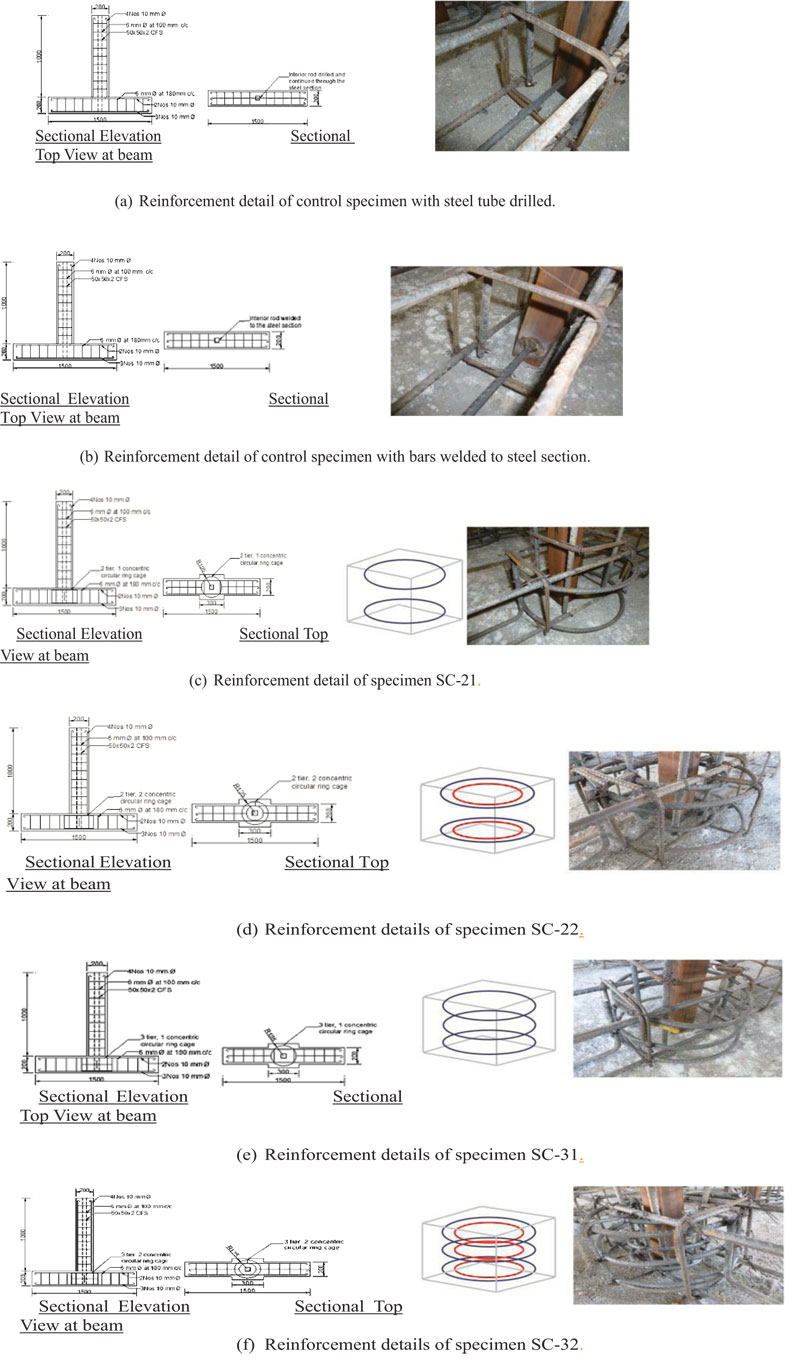
The behaviour of an individual beam-column connection of a frame determines the behaviour of the structure as a whole. The strength, deformation profile and energy absorption capacity of the connection has to be analysed to improve the performance of the structural members when subjected to the seismic load. During seismic loading, the forces accumulating at the structural connections affect the confinement of the concrete and the reinforcement bars that are subjected to fatigue load and lead to failure. The higher confinement of steel in the concrete increases the seismic performance of the structure. When the ECFST column is terminated at the joint and when there is a continuation of the reinforcements from the beam through the connection, higher confinement is achieved. However, the discontinuous steel tube affects the axial load capacity and moment carrying capacity of the column. If the steel tube of the column is continuous through the joint, there is some loss in the cross sectional area at the steel section when drilling is done to pass the longitudinal reinforcements, which leads to the reduction of the axial load carrying capacity. and if the longitudinal bars are welded to the steel tube of the column for continuity, the joint fails due to fracture at the welding connection. In this current investigation, the steel tube of the column is continued through the joint, and also the main reinforcement of the beam is continued by providing steel in the form rings at the joint and bound by the concrete casing. The moment transfer in the joint is ensured by the reinforcement continuity at the joint by these steel rings arrangement.
Nie et al. [1] tested specimens on a composite column with a tube filled concrete and reinforced concrete beams through-column connection with steel rings provided at the joint that acts as a stiffening ring. He experimentally observed that the load-carrying capacity and yield deflection to the ultimate deflection ratio got increased significantly. Raj and Joanna [2, 3] studied the square casing which has square rings having two layers with one internal ring and two layers with two internal rings. Square casing with square rings having three layers with one internal ring and three layers with two internal rings was also studied. The lateral load-carrying capacity, the ductility ratio and energy absorption capacity were found to be increased with the addition of concrete casing and steel ring. However, the results of the specimens with concrete casing and steel ring in square shape were not satisfactory when compared to the results of circular concrete casing and ring. Han et al. [4] conducted tests on steel tube confined concrete joints which performed well during seismic conditions when subjected to cyclic loading. Fan et al. [5] studied the performance of the CFST column and composite beams. It was concluded that beams behaved well in the seismic conditions at the connections when subjected to bidirectional reversal loads. Li and Han [6] performed real-time model experiments on beam-column joint which were under reinforced sections subjected to lateral load and observed that the concrete member had very low moment carrying capacity at the joint. Liao et al. [7] performed tests on ECFST column and RC beams under axial load and reversed cyclic loading. They concluded that it had more strength, ductility and energy absorption characteristics when subjected to seismic forces. Chen et al. [8] studied the behavior of connections in beams with CFST and also with a ring beam provided in the joint zone. It was concluded that the additional ring beam provided, showed favorable results in the cyclic loading tests. Bedirhanoglu et al. [9] tested the beam-column joint where, the longitudinal bars fastened in the joint with hooks at 90-degree and it was observed that the hook helped in sustaining the lateral load applied in reversal directions. Li and Chua [10] performed investigations on minimum reinforced sustainable concrete beam-column connections under simulated lateral forces, and concluded that concrete members with less weight were inferior in relaying the moments to the joint failing in tensile strength of concrete. Han et al. [11] analysed the thin-walled steel tube confined concrete to RC beam joint under cyclic loading and concluded that it could be adopted in earthquake zones. Wang et al. [12] examined the performance of circular and square CFST column with extended end plate connections and concluded that the seismic performances such as hysteresis behaviour, ductility and energy absorption showed positive results. Li and Han [13] conducted finite element analysis on the CFST column and RC slab joint under cyclic loading and compared with the experimental results of similar setup and observed that the analytical results were good. Zhang et al. [14] established a system of connection for concrete-filled twin steel tube and Reinforced Concrete beam and analyzed for seismic loading. They concluded that the new joint arrangement showed good aseismic behaviour.
Yet, literature related to the ECFST column and RC beam joint with continuous beam reinforcement and a disconnected steel section of the column at joint and different numbers of steel rings with square casing under axial loading and reversed lateral loading is not available.
However, similar to this research work was done by Nie et al. [1], where the reinforcements were provided in the form of rings at the beam-column joint through column connection. In this setup, the steel section of the column was continued in the joint instead of the beam reinforcement. The longitudinal reinforcement of the beam is continued in the joint (called as through-beam connection) and the connection is provided with the circular steel ring and square concrete casing at the ECFST column and RC beam under simulated seismic loading. The hysteresis behaviour, Envelope curves, the ductility of the connection, energy absorption capacity, stiffness degradation along with the equivalent viscous damping coefficient are discussed in this study.
2. MATERIALS AND METHODS
2.1. Test Specimen Details
An investigational study was performed on the connections of composite Encased Concrete Filled Steel Tubular (ECFST) Column and was compared with the reinforced concrete beam with circular steel ring and square concrete casing at the joint with different numbers of ring layers and concentric rings. An additional encasement of concrete in square shape covering the additional steel ring is provided at the beam-column joint. The specimen identity indicates the adopted shape of the casing as the first letter, adopted shape of the steel ring as the second letter, number of tiers as the third letter and number of concentric rings as the fourth letter. ‘S’ represents square shape and ‘C’ represents circular shape, for example, specimen ‘SC-21’ represents the specimen with ‘square casing’ and ‘circular steel ring’ with 2 ring layers and 1 concentric ring. The specimen SC-21 is shown in Fig.(1c). The particulars of the test models are given in Table 1. There are two control specimens in which one specimen has the steel tube of the column drilled known as ‘D’ which is to pass the interior main bar of RC beam for continuity, and other one is known as ‘W’ in which interior main bar is welded to the steel tube.
The column of the specimen is a reinforced concrete encased CFST where the steel section is a hollow square tube of lateral dimensions 50 mm and with a thickness of 2 mm. The column is square in cross-section, 1000 mm long and with a lateral dimension of 200 mm x 200 mm. The beam spans 1500 mm with a depth of 200 mm. The specimens were cast using Fe415 grade steel and M30 grade concrete [15]. The cubes were casted with a design mix of 1: 1.44: 2.10 and a water cement ratio of 0.4. The compressive strength is 32.5 N/mm2. Fig. (1) describes the particulars of reinforcement in the ECFST column and RC beam models.
2.2. Experimental Arrangement
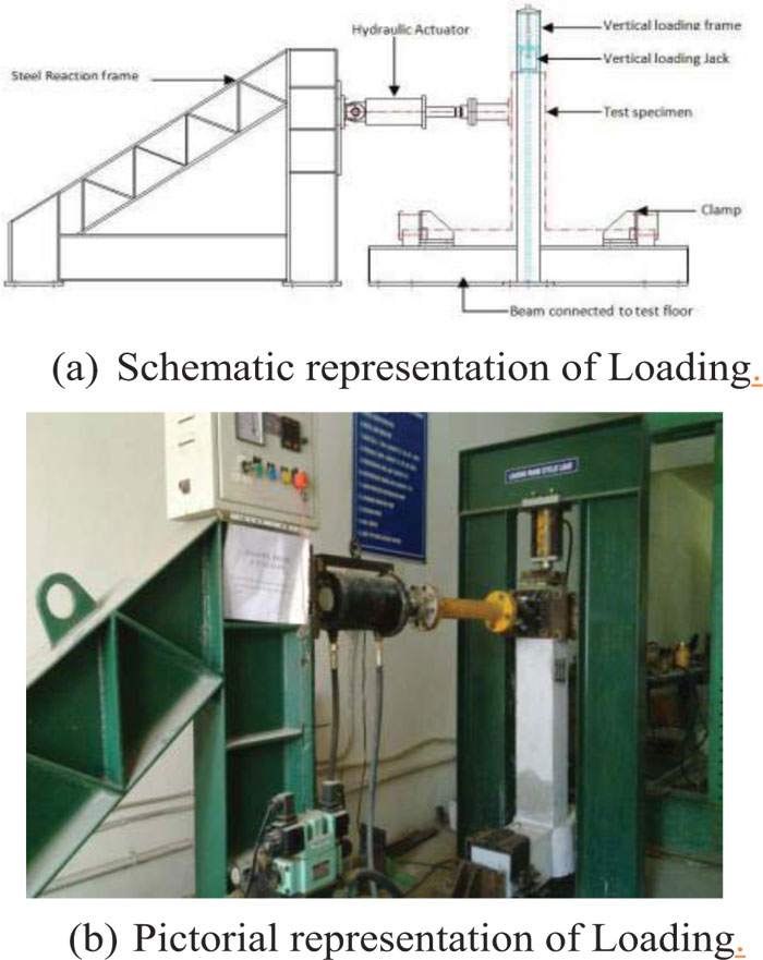
This experimental arrangement consists of a hydraulically operated lateral actuator with 200 kN capacity with a stroke limit of ±100 mm mounted on a steel reaction frame to apply lateral quasi-static load. A vertical hydraulic reaction jack of 100 kN is used to apply persistent axial load vertically to the beam-column joint specimens. The roller-plate arrangement is provided between the top of the column and the vertical hydraulic reaction jack [16]. Linear variable displacement transducer is used to determine the horizontal displacement at the top end of the column and the actuator system fixed to the load cell is used to record the reversed laterally applied loads. A design compressive load of 20% of axial resistance is applied vertically to the column [17]. The experimental arrangement which was done is described in Fig. (2).
| S.I | Specimen | Shape of casing | Shape of the steel ring | No. of Ring Layers | No. of Internal Rings | Reinforcement details | ||||
|---|---|---|---|---|---|---|---|---|---|---|
| Beam | Column | |||||||||
| Details of main reinforcement | Details of stirrups | Details of main reinforcement | Details of stirrups | |||||||
| 1 | D | Nil | Nil | Nil | Nil | Top has 2 numbers of 10mm dia bars and bottom has 3 numbers 10mm dia bars | 6mm dia bars@ 180mm c/c |
4 numbers of 10mm dia bars | 6mm dia bars at 100mm c/c | |
| 2 | W | |||||||||
| 3 | SC21 | Square | Circle | 2 | 1 | |||||
| 4 | SC22 | 2 | ||||||||
| 5 | SC31 | 3 | 1 | |||||||
| 6 | SC32 | 2 | ||||||||
3. RESULTS AND DISCUSSIONS
3.1. Lateral Load-Displacement
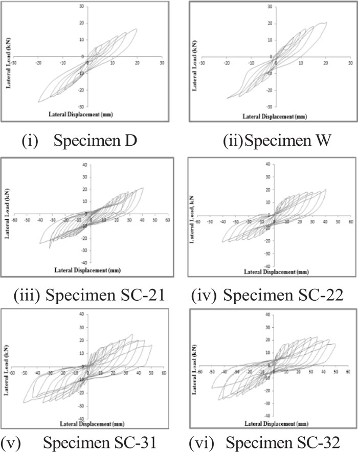
The relationship between the lateral load and the lateral displacement constitutes the hysteretic loop under cyclic loading, which is an important factor in seismic behavior analysis. In this study, the lateral load and displacement of the ECFST column and RC beam are measured for drawing the hysteresis loops. Fig. (3) shows the hysteresis loop obtained by plotting lateral displacement to lateral load of all the specimens. The hysteretic loops gradually rotate towards the horizontal direction and the loop area that expands gradually, means that the columns have reached their yield drift. Moreover, the structures have entered into the plastic phase.After this, the concrete of the beam end and the column bottom is crushed, and the reinforced bars yield successively. The residual deflection becomes more obvious, and the lateral load at the same drift rotation tends to decrease obviously with increasing cycle number. The control specimen ‘D’ failed at a load of 18.8 kN with a displacement of 19.4 mm and control specimen ‘W’ failed at a load of 19.9 kN with a displacement of 17.2 mm. The model specimens with square casing and circular steel ring, SC-21 and SC-22 gets collapsed at a lateral load of 21.1 kN & 20.7 kN with a lateral displacement of 35.7 mm & 35.6 mm respectively. Similarly the specimens SC-31 and SC-32 failed at a lateral load of 25.1 kN and 21.8 kN with a lateral displacement 39.1 mm & 41.2 mm respectively. Comparing the superior lateral load capacity among the control specimens (i.e. specimen W with load capacity 19.9 kN) with the load capacity of the specimens SC-21, SC-22, SC-31 and SC-32 are 7%, 4%, 26% and 10% respectively. The higher lateral load capacity in the specimens with the steel rings arrangement is achieved when compared with the control specimens which may be due to the increased confinement at the joint and the continuity of longitudinal bars of the beam [1, 18].
3.2. Envelope Curves
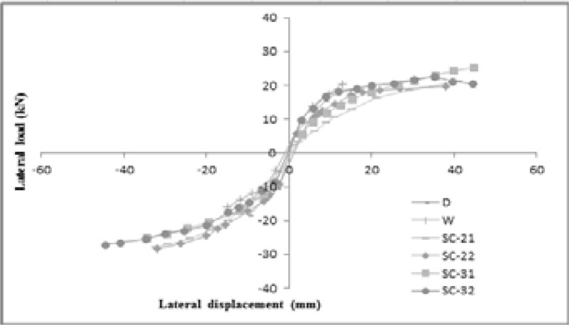
A cyclic envelope is a force-deformation curve that envelopes the hysteretic behaviour of a component or assembly that is subjected to cyclic loading. Fig. (4) shows a cyclic envelope of all the six specimens, which is defined by connecting the peak force responses at each displacement level. From the maximum lateral load capacity of the specimens, it is perceived that the strength of the model specimen SC-31 is 26% higher than the superior control specimen and 18%, 21% and 15% higher when compared to the specimens SC-21, SC-22 and SC-32. This increased performance can be accredited by the higher confinement achieved due to the optimum numbers of steel rings at the joint [18].
| S. No |
Specimens |
Displacement ∆y (mm) |
Max Displacement ∆u (mm) |
Ductility Ratio (μ) |
Average Ductility ratio |
% increase w.r.t 'D' | % increase w.r.t 'W' | |||
|---|---|---|---|---|---|---|---|---|---|---|
| +ve | -ve | +ve | -ve | +ve | -ve | |||||
| 1 | D | 7.55 | 6.49 | 19.00 | 19.80 | 2.52 | 3.05 | 2.78 | - | - |
| 2 | W | 6.95 | 7.34 | 17.50 | 16.90 | 2.52 | 2.30 | 2.41 | - | - |
| 3 | SC-21 | 9.91 | 13.2 | 35.30 | 35.90 | 3.56 | 2.72 | 3.14 | 13.0 | 30.3 |
| 4 | SC-22 | 8.09 | 7.9 | 35.20 | 35.90 | 4.35 | 4.54 | 4.45 | 60.0 | 84.6 |
| 5 | SC-31 | 8.16 | 8.2 | 38.90 | 39.30 | 4.77 | 4.79 | 4.78 | 71.9 | 98.3 |
| 6 | SC-32 | 8.30 | 9.98 | 40.90 | 41.50 | 4.93 | 4.16 | 4.54 | 63.4 | 88.5 |
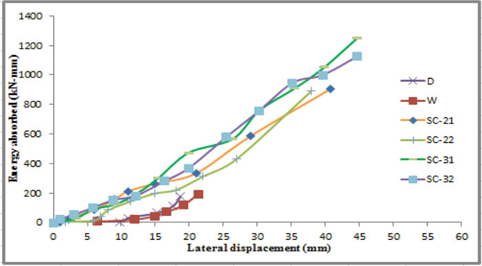
3.3. Energy Absorption Capacity
The area of each hysteresis loop gives the energy absorbed by the system during each cycle of load. To evaluate the performance of a structure under ‘Seismic Effects’, the ability to absorb the energy generated due to the ground-motion is the accurate measure. In this study, the energy absorbed by the tested specimens during reversed lateral load testing is calculated by measuring the area enclosed by each hysteresis loop during each cycle.
It is observed that the specimens with steel ring and concrete casing at the connection shows better performance than the control specimens. The energy absorption capacity of the specimen SC-21, SC-22, SC-31 and SC32 was 906 kN-mm, 893 kN-mm, 1250 kN-mm and 1123 kN-mm respectively. Also, the energy absorption capacity of the control specimen D and W is 389 kN-mm and 459 kN-mm. It is observed that the specimen with three ring layers and one concentric ring (SC-31) exhibits 1.7 times higher energy absorption capacity than the superior control specimen (W). The energy absorption performance of the model specimens are shown in Fig. (5).
3.4. Ductility
The capacity of a structure to experience excessive deformation and not losing much of the strength is defined as ductility. It is usually quantified by a non-dimensional value called ‘ductility ratio’ which is obtained by the ultimate displacement to the yield displacement as shown in eq. 1. The displacement corresponding to the 85% of the utmost load is taken as the yield displacement. Tables 2 and 3 shows the displacement at forward (+ve) and reversal (-ve) directions and the ductility ratio (μ) of the specimens and the percentage increase with respect to the control specimens.
 |
(1) |
The ductility ratio of the specimens and the percentage of variation of the values w.r.t. control specimens are shown in Table 2. Among the two control specimens, the specimen ‘D’ shows higher ductility ratio of 2.78, whereas in the specimens SC-31 with steel ring shows an average ductility of 4.78 which is 72% more than that of the relatively superior control specimen D. The specimen with ‘square casing’ and ‘circular steel ring’ with 3 ring layers and 1 concentric ring beam ensures an adequate ductility which protects the beam-column joint from brittle failure and provides an adequate energy dissipation capacity through the behaviour of the beam. The increased ductility ratio may be due to the additional steel rings provided at the joint providing flexibility to the system [18].
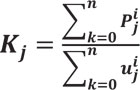
3.5. Rigidity Degradation
Many structural components and systems will exhibit some level of stiffness degradation when subjected to reverse cyclic loading. Stiffness degradation in reinforced concrete components is usually the result of cracking, loss of bond, or interaction with high shear or axial stresses. The level of stiffness degradation depends on the characteristics of the structure as well as on the loading history. The rigidity degradation is calculated as per the specification of testing methods for earthquake resistant buildings JGJ101-9 [19] as given in Eq. 2.
 |
(2) |
Where, Kj is the rigidity degradation of the beam column joint because of the reversed lateral loading and extended displacement. Pij represents the maximum load and uij denotes accord with the displacement at the ith cycle. The control specimen D and W has an initial rigidity of value of 845.4 N/mm and 792.3 N/mm, whereas, among the specimens with the steel ring at the joint, the specimen SC-31 has the highest initial rigidity value of 1558.2 N/mm and which is 85% more than that of the control specimen with highest rigidity. This significant improvement in the initial rigidity is due to the unaffected steel tube (avoiding the drilling or welding) and the progression of the main reinforcement of the beam and the higher confinement achieved due to the steel rings at the joint [20].
3.6. Equivalent Viscous Damping Coefficient
The equivalent viscous damping coefficient (he) is a form of expressing the energy-absorption and it is expressed as in Eq. 3 [21].
 |
(3) |
where Sloop is the area of a single hysteresis loop, S∆+ and S∆- are the area of triangle covered by line joining the points of (1) origin, (2) peak load in +ve or –ve respectively, and (3) abscissa of peak load. The he of the control specimen ‘D’ and control specimen ‘w’ 0.10 and 0.08 respectively, and the specimen SC-31 is 0.16 [22]. From the results, it is observed that the specimens with stiffening rings are significantly higher in the viscous damping coefficient when compared with the control specimens. The reason for this better performance might be due to continuity of the reinforcement of the beam and the steel section of the column at the joint by the stiffening rings.
4. Numerical Study
4.1. Finite Element Modelling
The finite element models of the beam-column joint specimens are created using ANSYS software package. The reliability of the load-deflection from the test results is confirmed by the numerical results acquired from the analysis. In order to get the unique solution from the FEM models, the boundary conditions given to the numerical models are replicating the natural conditions of the experimental setup.
4.2. Selection of Elements
In the process of finite element model analysis in ANSYS, pre-processing, solution and post-processing stages has to be performed. Modeling of the specimen geometry, assigning of element type, assigning of real constant, material property, discretization of mesh size, boundary conditions and load applications are done in pre-processing stage. Every factor is assigned in the simulation of experimental specimens in the FEA pre-processing stage.
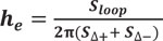
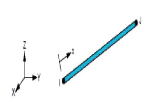
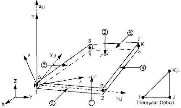
Concrete is represented as SOLID65 element and the main reinforcement is represented as LINK 8 element in ANSYS software. The capability of solid to experience splits in tension, compression and also creep in all three orthogonal directions, made the SOLID65 element suitable for 3-D numerical modeling of concrete [23]. Also, this element is suitable for simulating concrete with and without reinforcement, thus making it suitable for representing concrete without reinforcement inside the steel tube. The pictorial representation of the SOLID65 element is shown in Fig. (6) and LINK8 element is shown in Fig. (7).
SHELL63 element is used to identify the cold-formed steel tube of the specimen in the numerical model. This element has the capability of bending and also has membrane characteristics. The shell thickness is assigned to replicate the value of cold-formed steel and the real constant value is given as 2.30 mm. Fig. (8) shows the SHELL63 element.
The contact between the concrete (SOLID65 element) and reinforcement (LINK8 element) is established by providing interaction between them. For contact between the concrete (SOLID65 element) and cold-formed steel (SHELL63 element) ‘surface to surface contact’ is developed. This develops contact between either side of the CFS tube with the encasing concrete and infill concrete respectively.
4.3. Mechanical Properties
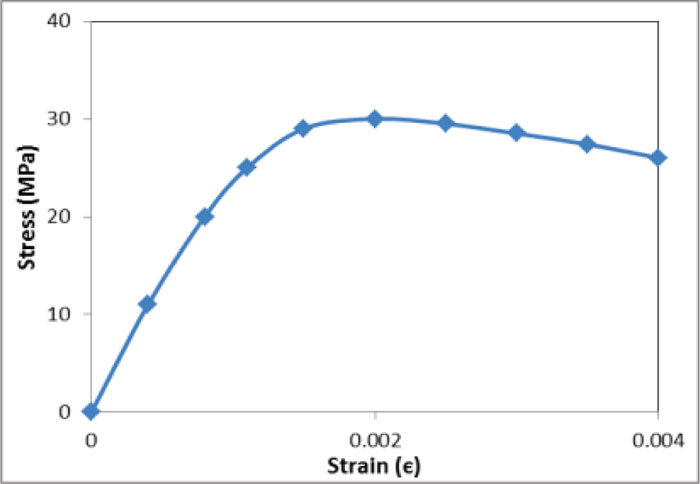
The grade of concrete used in the experiment is M30 and the multi-linear isotropic property representing the stress (σc) versus strain (єc) behaviour is studied under compression test as per IS: 516 – 1959 [24]. Table 3 shows the concrete material properties obtained from the compression study. This multi-linear curve shown in Fig. (9) is assigned to the ANSYS concrete model [25-27].
| Sl. No. | Mechanical properties | Values |
| 1 | Compressive strength | 32.5 N/mm2 |
| 2 | Density | 2450 kg/m3 |
| 3 | Young’s modulus | 27215.09 N/mm2 |
| 4 | Poisson’s ratio | 0.2 |
| 5 | Maximum strain | 0.004 |
| S. No. | Particulars | Values |
| 1 | Modulus of Elasticity | 2.11X10⁵ N/mm2 |
| 2 | Yield strength | 417 N/mm2 |
| 3 | Poisson’s ratio | 0.3 |
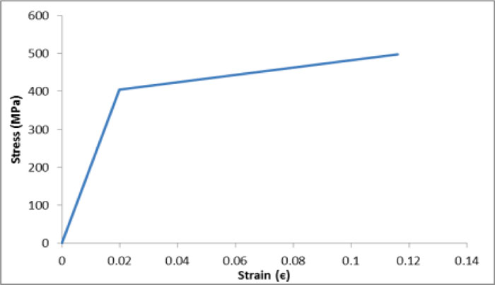

The properties of steel are obtained from standard tests as per ASTM 370. The bilinear curve representing the stress versus strain relationship of the steel is exhibited in Fig. (10). The mechanical properties of the steel are given in Table 4. This stress-strain relation and the material properties are assigned to the ANSYS steel model.
4.4. Meshing
The meshing of the finite element model is an important phase of the numerical modelling which will determine the degree of accuracy of the outputs from the analysis. It is important to choose an appropriate dimension of the mesh forthe model which gives a converged solution. The ‘smart size’ option for the meshing is chosen in the ANSYS and the mesh refinement size is chosen as ‘4’. The nodes of the speci- men where the load is applied, are constrained in the direction perpendicular to the direction of application of the load. The nodes of the model specimen which are fixed in the experi- mental setup are simulated by providing fixed condition in the ANSYS constraining the degree of freedoms in X, Y and Z directions. Fig. (11) shows a typical ANSYS model of speci- men, which is assigned with support boundary conditions [28].
4.5. Comparison of Experimental and Numerical Results
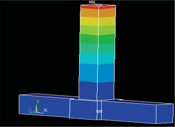
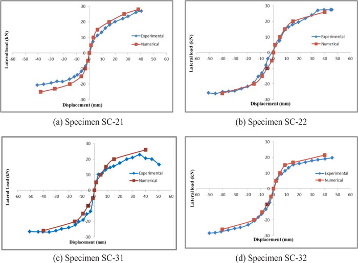
The peak load analysis of the numerical models are performed using ANSYS and a plot between the peak lateral load with the corresponding displacement are drawn. The numerical analysis is made only for the specimens with steel rings at the joint and not for the control specimens. The input for the numerical investigations are the data from the output of this investigation and the observed deflections at the peak load of each cycle is closely similar to the numerical failure model which are alike to the experimental investigation results. The deformed ANSYS model of a typical specimen is shown in Fig. (12). The numerical results are compared with the investigational outputs and the superimposed curves are shown in Fig. (13a-d). The experimental and numerical contrast values of load (P) and displacement (δ) at yield point of the specimens are given in Table 5. From the degree of variance in the values of experimental and numerical outcomes, it is perceived that the numerical outcomes have concurred with the experimental values obtained [29].
| S. No. |
Specimens | Yield Displacement(mm) | δExp / δNum | Yield Load (kN) | PExp / PNum | ||
|---|---|---|---|---|---|---|---|
| δExp | δNum | PExp | PNum | ||||
| 1 | SC-21 | 9.91 | 8.90 | 1.113 | 13.23 | 15.38 | 0.860 |
| 2 | SC-22 | 8.09 | 8.10 | 0.998 | 14.16 | 14.82 | 0.955 |
| 3 | SC-31 | 8.16 | 7.85 | 1.039 | 12.49 | 13.34 | 0.936 |
| 4 | SC-32 | 8.30 | 9.17 | 0.905 | 10.21 | 11.16 | 0.915 |
| Mean Variance | 1.014 | Mean Variance | 0.916 | ||||
CONCLUSION
In this paper, four composite structural joints between Encased Concrete-Filled Steel Tubular (ECFST) Column and conventional Reinforced Concrete (RC) beam with circular steel ring and square concrete casing along with two control specimens for the study are examined. Under axial load and reversed lateral loading are also studied and the seismic characteristics were compared. The following conclusions are drawn from the comparison of the results obtained.
- The specimen with ‘Square casing’ and ‘Circular steel ring’ with 3 ring layers and 1 concentric ring (SC-31) at the joint shows a substantial increase in the lateral load strength by 26% than that of the specimens with conventional drilling and welding at the joint.
- The specimen SC-31 exhibits a higher ductility ratio of 4.78, which is about 72% higher than the control specimen.
- The specimen with ‘Square casing’ and ‘Circular steel ring’ with 3 ring layers and 1 concentric ring (SC-31) behaves well during seismic conditions when compared to the control specimens which are validated with the energy absorption capacity, initial rigidity, and equivalent viscous damping coefficient due to the optimum number of stiffening rings which provides the highest confinement and seismic performance.
- It is found that the numerical behaviour of the specimens are comparable with the investigation results at yield zone, which means the proposed numerical analysis can be applied to predict the seismic behaviour accurately for the composite structural connection of the encased CFST column and reinforced concrete beam with steel ring.
Thus, it is concluded that the ECFST Column and RC beam joint specimen with three ring layers and one concentric ring in square shape with square concrete casing exhibits superior seismic performances such as increased lateral load capacity, good ductile behaviour, better energy absorption, rigidity, and improved equivalent viscous damping coefficient due to the optimum proportion of the volume of encased concrete to the volume of steel in the ring.
AVAILABILITY OF DATA AND MATERIALS
Not applicable.
FUNDING
None.
CONFLICT OF INTEREST
The authors declare no conflict of interest, financial or otherwise.
ACKNOWLEDGEMENTS
Declared none.

