All published articles of this journal are available on ScienceDirect.

Stability Analysis of Dike to Impound Freshwater in Brackish Water Estuarine Environment
Abstract
This paper presents the stability analysis of a dike proposed to impound the river flood waters within an estuary near the west coast of south India. The proposed dike will be located within Ashtamudi Lake, the second largest lake in the state of Kerala, India, separating fresh water from brackish water. Constructing a dike at Munro Island portion of Ashtamudi, which is about 9.23 km from Arabian Sea coast, can meet the water demands of the region as well as prevent the sinking of Island during high tide. The river dike is designed to construct artificially as rock filled structures. The stratigraphy in the top 2 m consists of clayey mud underlined by fine to medium sand up to 6 m followed by alternate layers of clay and sand up the investigated depth of 15 m. In this paper, the stability of the dike located in an estuarine environment has been investigated and the factor of safety values have been determined with varying water level conditions and varying properties of the underlying soil. A detailed parametric study using RocScience software is presented, considering all the design conditions. The expected settlement of the dike is estimated considering the soil profile at the location both manually as well as using software Geo5. Both were in good agreement and the maximum possible settlement was found to be less than half a meter.
1. INTRODUCTION
River dikes may be subject to instability and settlement because of human and natural activities, and variation in water level. Since the underlying soil is soft soil in most of the river beds, the construction is challenging. The change in the pore pressure distribution due to change in water level affects the strength of the soil, which affects the stability of the dike [1]. Ensuring the safety of dikes is of great significance. Seepage failure and other failures associated with seepage are the main forms of failures in the dike engineering during the flood period. Upon the infiltration of the flood, the stability problem of the dike engineering is a very complicated process, which involves water movement in saturated-unsaturated states and the decrease in the strength of the unsaturated soil. The study of the dike stability mechanism under the seepage of the flood would be useful in reinforcing embankment and effective preventing damages due to flood. The effect of flood level on river dike is a typical unstable seepage process [2]. The drawdown rate also has a significant effect on the safety factor of dike stability. The main threats to water level rise to dike stability are indirect impacts such as accelerated erosion, scouring, and water overtopping-induced soil erosion on the slopes. Slope stability of the dike become more complex because of seepage conditions of rainfall infiltration or the water level rise.
Past studies have been using the finite element method to analyse the impact of pore pressure changes on the deformation and stability of geotechnical structures, [1, 3-6]. Computation of the factor of safety is the most critical aspect of the analysis and design of any river dike. Ordinary method of slices, Bishop’s method, force equilibrium method, Janbu’s generalized method, Morgenstern and Price’s method and Spencer’s method are the different conventional limit equilibrium methods being widely used to compute the Factor of Safety (FS). For stability analysis of river dikes, soil profile and water level variations are important and there is little information available about stability analysis for a dike in an estuarine environment.
In this paper, a case study has been undertaken, where the stability of a dike located in an estuarine environment has been investigated. The factor of safety values has been determined with varying water level conditions, varying properties of underlying soil and parametric studies using RocScience software. There exists less information regarding the studies done in RocScience software, as the majority of investigators adopted finite element method and strength reduction method using software like PLAXIS. In this case, stability analysis is done considering base failure, as the embankment rests on soft soil foundation. The other major factor influencing the dike is the settlement. In this paper, time-dependent consolidation settlement analysis is done both manually and using geotechnical software namely, GEO5. GEO5 is popularly used to determine vertical settlement and time-dependent consolidation of soils under embankments, foundations, earth dams and surface loads (surcharges).
2. STUDY AREA
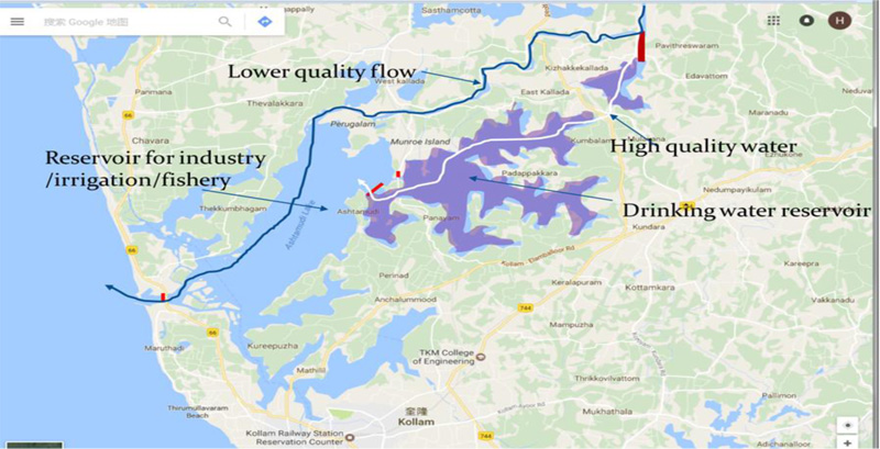
Ashtamudi Lake (8°59’N 76°36’E), in the Kollam district of Kerala (India), is the second largest wetland in the Kerala state (Fig. 1). It owns a different wetland ecosystem and a large palm-shaped water body. The name, Ashtamudi denotes the lake's topography with its eight multiple branches. The lake which is the strength of tourism sector of Kerala state is also called the gateway to the backwaters of Kerala. The Kallada River, which is the conflux of three rivers, Kulathupuzha, Chenthurnipuzha, and Kalthuruthipuzha, originates near Ponmudi from the Kulathupuzha hills, Western Ghats. The river after flowing about 121 km distance through the forests finally debouches into the Ashtamudi wetland. As the name, the lake has eight arms; all the arms of Ashtamudi Lake are then merging with the Arabian Sea at Neendakara, the fishing harbor near Kollam, where the maximum depth is measured as 6.4m. Ashtamudi wetland is an estuary filled with brackish water and sewage.
3. FRESHWATER STORAGE STRATEGY
Ashtamudi is a brackish water lake and even if one mudi (arm) is replaced with fresh water it can augment the water demand of Kollam and adjacent regions throughout the year [10]. Constructing a dike at Munrothuruthu portion of Ashtamudi Lake, which is about 9.23 km from Arabian Sea coast, can meet the water demands of the district as well as prevent the sinking of Munro Island (Figs. 1 and 2). The storage capacity of proposed reservoir and length of the dike are estimated as 3 TMC (thousand million cubic feet) and 267 meters, respectively, using Google Earth software.

4. SOIL PROPERTIES
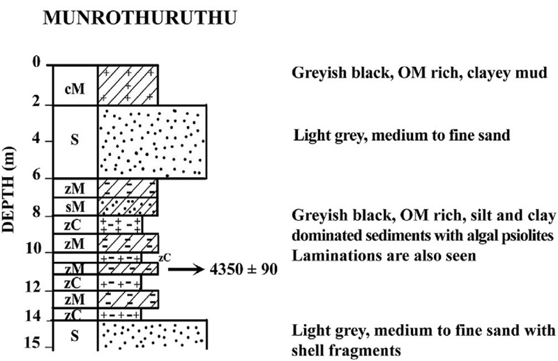
The bore log details of Munroe Island (Munrothuruthu) region show the presence of sand and clay for about 15 m below the water level (Fig. 3).
4.1. Slope Stability Analysis
Slope stability analysis requires:
a. Establishing the design and loading conditions for the embankment.
b. Performing analyses of stability for each of the following conditions. The design conditions considering for embankments are:
• At the end of construction
• Steady-state seepage
• Rapid drawdown
• Earthquake loading.
4.2. Design Conditions
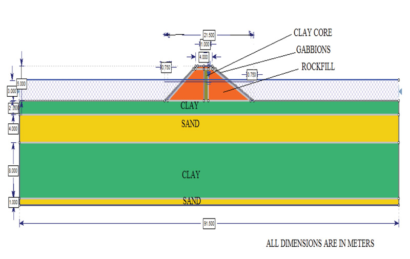
The design conditions to which the slope may be subjected during its life need to be established before the stability analysis. The cross section details are shown in Fig. (4). Design cross sections of the dike are selected on the basis of geological conditions, materials used for the construction of dike, filling materials, external forces, operational requirements, etc. The top width of the dike is chosen to satisfy the minimum requirement of having road connectivity between two ends of the dike across the lake. The design conditions and dimensions are shown in Table 1. The embankment can be designed as trapezoidal rock-filled dams with upstream slope 1:1.5 and downstream slope 1:2 lying in soil boundary conditions (0, 0), (91.5, 0), (91.5, 15) and (0, 15). It can be built with clayey sandy gravels having a size between 50 – 0.075 mm. An increase in particle size would lead to more cracks and defects. These materials can arrest seepage as well as give protection to the impervious earth core using in the middle. Earth core can be used in the middle portion instead of an impervious upstream membrane to prevent seepage. Gabions can be used as the boundary layer to direct the force of a flow of flood water around a vulnerable structure. The material and soil properties considered in this study are shown in Table 2.
| Design Conditions | Dimensions |
|---|---|
| Top width | 4 m |
| Bottom width | 21.5 m |
| Head | 5 m |
| Water level | 3 m |
| Slope at upstream | 1:1.5 |
| Slope at downstream | 1:2 |
| Capacity | 3TMC |
| Length of dike | 267 m |
| Materials | Cohesion (kPa) | Angle of Friction (degrees) |
Dry Unit Weight (kN/m3) |
Saturated Unit Weight (kN/m3) |
|---|---|---|---|---|
| Sand | 0 | 27 | 16 | 18 |
| Clay | 30 | 12 | 15 | 17.2 |
| Clay core | 50 | 15 | 16 | 18 |
| Infill | 15 | 30 | 16 | 18.3 |
| Gabbions | 15 | 30 | 16 | 20 |
4.3. Stability Analysis
Analysis can be done for each conditions using Slide product of RocScience software. Slide is the most comprehensive 2D limit equilibrium slope stability analysis program being used for evaluating the safety factor or probability of failure, of circular or non-circular failure surfaces in soil or rock slopes. The software is complete with finite element groundwater seepage analysis, rapid drawdown, sensitivity and probabilistic analysis, and support design. All types of soil and rock slopes, embankments, earth dams, and retaining walls can be analyzed.
Limit Equilibrium (LE) methods have been the primary method used in determining the stability of slope for decades. The procedures are based on finding a factor of safety (FS) for the slope. The FS shows the factor by which the shear strength must be reduced, so that the reduced strength just reaches equilibrium with the shear stress. The definition of limit equilibrium can be expressed in the form of Eq. 1.
τ= s/FS (1)
where s: Shear strength of the soil; τ: Shear stress in the soil mass. Slopes can be classified as infinite slopes or finite slopes. An infinite slope represents a slope with translational failure along a single plane. The ratio of depth to failure surface to length of failure zone is relatively small <10. The soil type in this failure is usually granular. Bishop’s Simplified Method is a common method for slope stability analysis and is employed in this study. The interslice shear forces are assumed to be zero by Bishop (1955), leaving the solution over-determined as horizontal force equilibrium will not satisfy for one slice. This method satisfies the vertical force equilibrium for each slice and the overall moment about the center of the circular trial surface.
4.3.1. End of Construction
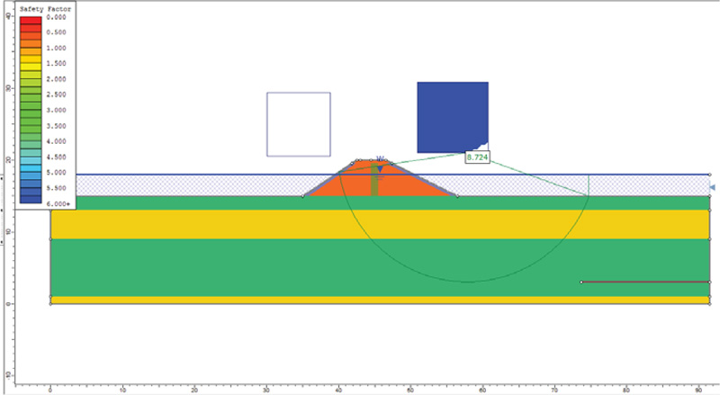
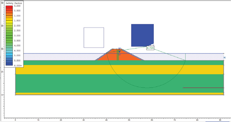
The stability analysis at the end of construction was carried out using drained strengths in free-draining materials and undrained strengths in materials that drain slowly. This analysis is done to study the effect of pore water pressure. The analysis is done for upstream and downstream with and without earthquake loading. The factor of safety obtained is greater than 1.3 factor of safety obtained (Figs. 5 and 6) (Table 3). Hence, the slope is stable. The factor of safety values obtained for conditions with earthquake loading is less because shear forces get generated due to earthquake forces. Besides this, the increased pore water pressure reduces the available shear strength.

| Conditions | - | Factor of Safety | |
|---|---|---|---|
| With Earthquake | Without Earthquake | ||
| End Of Construction | Downstream | 5.750 | 8.724 |
| Upstream | 5.841 | 7.913 | |
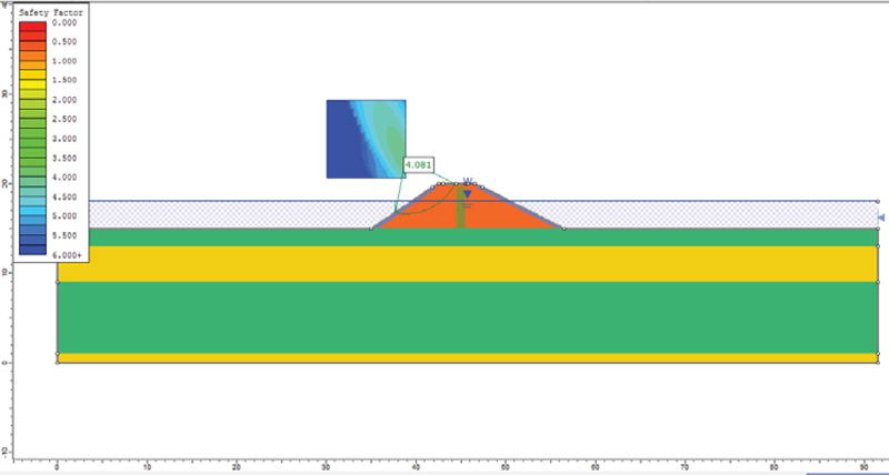
| Steady Seepage | Downstream | 3.541 | 8.724 |
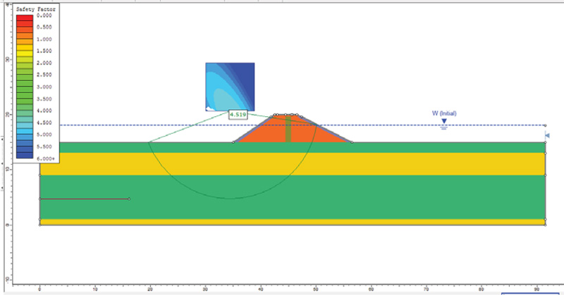
| Rapid Drawdown | Upstream | 3.792 | 4.519 |
4.4. Steady Seepage
The side slopes become more susceptible to instability when seepage forces act along with the forces due to gravity. The shear strength will reduce with the increase in pore water pressure. Steady seepage condition is critical for the downstream slope. The analysis was done for steady seepage with and without earthquake loading. The factor of safety obtained is greater than 1.5 (Fig. 7) (Table 3) with and without earthquake loading. Hence the slope is stable under steady seepage condition.
4.5. Rapid Drawdown
Here, the slopes become unstable because of the reversal in the flow direction of the water. Due to higher saturated unit weight, shear stresses are more during the rapid drawdown. But due to pore water pressure that doesn't dissipate quickly, the shearing resistance decreases. This condition is critical for the downstream slope. The analysis was done with and without seismic loads (Fig. 8) (Table 3). The factor of safety obtained is greater than 1.3 with and without seismic loading. Hence, the slope is found to be stable under rapid drawdown condition as well.
4.6. Seismic Loading
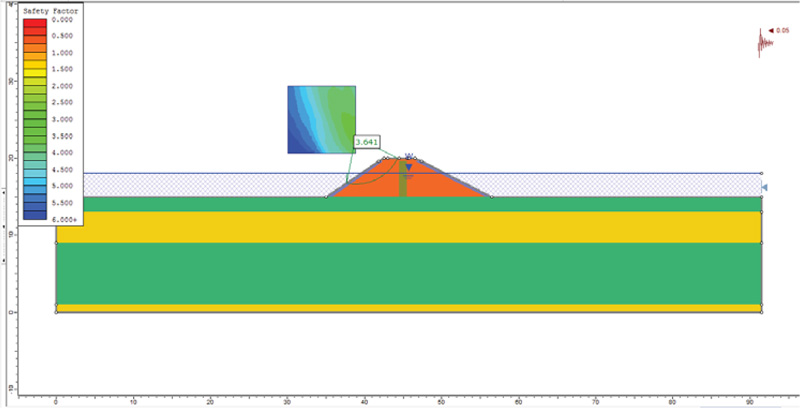
To understand the effect of seismic loading on slope stability, further analysis was performed considering appropriate earthquake force and compared with static condition (Figs. 9 and 10). In Slide, pseudo-static seismic loads can be applied in the horizontal and vertical directions by specifying the corresponding seismic coefficient. To replicate the seismic condition of the study region, the seismic coefficient is taken as 0.05 for Kollam [7]. The factor of safety obtained with seismic conditions is 3.641 and without seismic conditions are 4.081. The factor of safety obtained is found to be greater than 1 even with seismic forces. Hence, the slope is stable even with maximum seismic loading expected for the study region. The factor of safety values obtained for conditions with earthquake loading is less because shear forces get generated due to earthquake forces. Besides this, the increased pore water pressure reduces the available shear strength.
5. VARYING THE UNDERLYING SOIL PROPERTIES
The analysis was done by changing the soil properties of underlying soil since stability analysis and base failure are important in the study of slope stability of dike in the estuarine environment, which lies on soft soil. The values of different properties are shown in Table 4. The analyses with varied underlying soil properties were performed for all the three conditions (Table 5). As evident from the factor of safety values reported in Table 5, the slope was found to be stable for all analyses performed. So the minimum cross section considered to satisfy the functional requirements is safe.
| Materials | Cohesion (kPa) | Angle of Friction (degrees) |
Dry Unit Weight (kN/m3) |
Saturated Unit Weight (kN/m3) |
|---|---|---|---|---|
| Sand | 0 | 20 | 16 | 18 |
| Clay | 10 | 12 | 15 | 17.2 |
| Clay Core | 50 | 15 | 16 | 18 |
| Rockfill | 15 | 30 | 16 | 18.3 |
| Gabbions | 15 | 30 | 16 | 20 |
| Conditions | Factor of Safety | ||
|---|---|---|---|
| With Earthquake | Without Earthquake | ||
| End of Construction | Downstream | 2.576 | 6.350 |
| Upstream | 4.190 | 5.625 | |
| Steady Seepage | Downstream | 2.576 | 3.271 |
| Rapid Drawdown | Upstream | 2.667 | 3.145 |
6. VARYING THE WATER TABLE LEVEL
The analysis was done by assuming the water table level at the ground surface in the downstream portion of the embankment to replicate worst case scenario (Table 6). The force due to water and seepage will act as an equivalent force and the water pressure tend to reach equilibrium on both sides when there is water on both upstream and downstream portion. So the factor of safety is more when the water level is the same on both sides of the embankment. So the barrier need not be highly resistant to pressure as it is the case with inland dams.
| Conditions |
Factor of Safety (without earthquake) |
|
|---|---|---|
| End Of Construction | Downstream | 5.088 |
| Upstream | 9.272 | |
| Steady Seepage | Downstream | 3.422 |
| Rapid Drawdown | Upstream | 5.146 |
7. RESULTS AND DISCUSSION
The saturated weight of soil increases the load on the dike, while the water pressure decreases its resistance. The strength of a dike with respect to slope stability is expressed in terms of factor of safety. The factor of safety is defined as the ratio of maximal resisting force and the driving force. The maximal resisting force is determined by the shear strength of the soil. The shear strength is expressed in terms of cohesion and friction angle. The combinations of cohesion and friction angle are one of the major sources of uncertainties in dike design. The combinations of cohesion and friction angle are therefore chosen to be the variables that determine the partial safety factors [8].
7.1. Cohesion
The analysis was done for different values of cohesion keeping all the other values constant for the embankment fill material for the parametric study. The value of factor of safety decreases with the decrease in the cohesion of the material and the variation is quantified in Table 7.
| C values | Factor of Safety |
|---|---|
| 15 | 3.362 |
| 14.25 (-5%) | 3.257 |
| 15.75 (+5%) | 3.467 |
| 13.5 (-10%) | 3.152 |
| 16.5 (+10%) | 3.573 |
| 12.75 (-15%) | 3.048 |
| 17.25 (+15%) | 3.678 |
| 12 (-20%) | 2.943 |
| 18 (+20%) | 3.783 |
7.2. Angle of Friction
The analysis was done for different values of angle of friction keeping all other values same for the embankment fill material for the parametric study. The value of the factor of safety decreases with the decrease in the angle of friction of the material, which is presented in Table 8.
7.3. Settlement Calculations
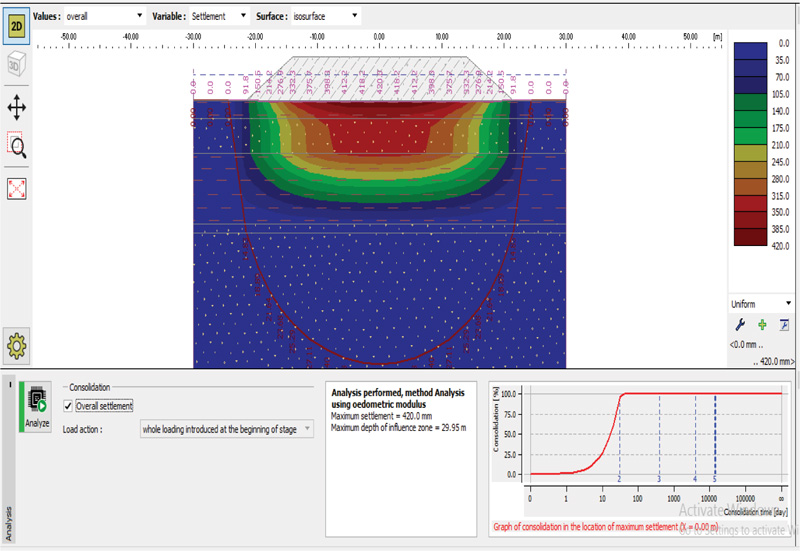
The study location consists of clayey mud (2 m) and fine to medium sand (4 m). It is then followed by grayish black OM rich silt and clay-dominated sediments with algal pisolites laminations for 8m and light grey medium to fine sand with shell fragments (Fig. 3). An attempt has been made to estimate the expected settlement for the proposed estuarine dike having 5m height and a base width of 21.5 m with an assumed density of infill as 18.3 kPa. The assumed design profile is given in Table 9. Immediate settlement for sand and consolidation settlement for clay are taken for settlement calculation. Settlement analysis was done with both manual calculations using the GEO5 software. Boussinesq's Method is employed for surcharge load in manual calculations. The overall settlement is taken as the sum of immediate settlement and consolidation settlement. The settlement obtained through manual calculations is 0.4733 m (Tables 10 and 11) and through GEO5 software is 0.42 m Fig. (11, Table 12). In a similar analysis for a coastal reservoir in Netravati River, Parthasarathy et al. (2018) reported a settlement up to 1.5 m for a proposed sea dike 6 km off Ullal coast [11].
Table 8.
| ᶲ values | Factor of Safety |
|---|---|
| 15 | 3.362 |
| 28.5 (-5%) | 3.300 |
| 31.5 (+5%) | 3.427 |
| 27 (-10%) | 3.239 |
| 33 (+10%) | 3.494 |
| 25.5 (-15%) | 3.179 |
| 34.5 (+15%) | 3.563 |
| 24 (-20%) | 3.121 |
| 36 (+20%) | 3.635 |
| Depth, m | Soil Strata |
Angle of Internal Friction, (Degree) |
Coefficient of Volume Expansion mv, cm2/kg |
SPT N |
|
|---|---|---|---|---|---|
| From | To | ||||
| 0 | 2 | CLAY | 12 | 0.3122 | 4 |
| 2 | 6 | SAND | 27 | 13 | |
| 6 | 14 | CLAY | 12 | 0.3122 | 4 |
| 14 | 15 | SAND | 27 | 13 | |
| CONSOLIDATION SETTLEMENT (CLAY) | ||
|---|---|---|
| Depth (m) | 0-2 | 6-14 |
| Coefficient of Volume Expansion mv, cm2/kg | 0.3122 | 0.3122 |
| Load, Q (kPa) | 91.5 | 91.5 |
| Depth from point of application of load,z (m) | 2 | 14 |
| Surcharge load, Δσ = 3Q/2πz2(kPa) | 10.92 | 0.2229 |
| Consolidation settlement, Sc = mvHΔσ (m) | 0.0682 | 5.567x10⁻³ |
| IMMEDIATE SETTLEMENT (SAND) | ||
|---|---|---|
| Depth (m) | 2-6 | 14-15 |
| Pressure on the sand layer from Dike, q (kPa) | 91.5 | 91.5 |
| Μ | 0.3 | 0.3 |
| Es = 320(N+15) (kPa) | 8960 | 8960 |
| Is | 1 | 1 |
| Base width, B (m) | 21.5 | 21.5 |
| Immediate Settlement, Si = qB(1-μ2)Is/Es(m) | 0.19979 | 0. 19979 |
| SAND | CLAY | EMBANKMENT | |
|---|---|---|---|
| Dry unit weight (kN/m3) | 16 | 15 | 16 |
| Saturated unit weight (kN/m3) | 18 | 17.2 | 18.3 |
| Poisson’s ratio | 0.3 | 0.35 | 0.3 |
| Oedometric modulus (MPa) | 30 | 1 | 30 |
| Coefficient of permeability (m/day) |
1x 10⁻² | 1x 10⁻⁵ | 1x 10⁻² |
| Overall settlement (m) | 0.42 | ||
CONCLUSION
This study presented stability analysis and settlement calculations for a proposed dike in an estuarine environment to separate freshwater from brackish water. On one side of the dike is freshwater and the other side brackish water, both the levels which may vary from time to time which differentiates this dike from normal river dikes. Through the stability analysis using Slide (RocScience), the factor of safety for the dike under different conditions was calculated. The proposed dike with minimum functional dimensions is satisfying all the conditions of stability analysis such as the end of construction, steady seepage, rapid drawdown and seismic loading conditions. The factor of safety values under earthquake loading is comparatively less as shear forces are generated due to earthquake forces. Besides this, the increased pore water pressure reduces the available shear strength. The factor of safety is more when the water level is same on both sides of the embankment, which indicates the benefit of coastal reservoirs over inland dams in terms of stability. Stability analysis and base failure are important in the study of slope stability of dike on soft soil in the estuarine environment. Therefore, the effect of changing soil properties on the stability was analyzed and presented. Besides this, the effect of soil parameters like cohesion and the angle of friction on the stability of the considered slope were presented in the paper. The value of the factor of safety decreases with the decrease in the angle of friction and cohesion of the material. The overall settlement of the proposed dike was calculated considering the soil profile manually and verified using the software. The expected settlement was found to be less than half a meter, which indicates that the dike at the proposed location is feasible.
CONSENT FOR PUBLICATION
Not applicable.
FUNDING
None.
CONFLICT OF INTEREST
The authors declare no conflict of interest, financial or otherwise.
ACKNOWLEDGEMENTS
Authors acknowledge the support received from Prof. TG Sitharam Indian Institute of Science Bangalore for carrying out stability analysis presented in this paper.

