All published articles of this journal are available on ScienceDirect.

The Behavior of Concrete-Filled Single and Double-Skin uPVC Tubular Columns Under Axial Compression Loads
Abstract
Background:
There is an increased demand for high-performance materials in the construction industry due to high cost, difficulty of sourcing and shortcomings of the existing construction materials. Some of the deficiencies are corrosion of steel, brittle failure and rapid deterioration of reinforced concrete structures in a harsh environment. Nowadays, there is also a shift from one material to another due to the difficulty of sourcing i.e. timber electric poles to concrete poles due to the difficulty of sourcing. These situations have triggered the interest to develop an alternative structural system.
Objective:
This paper presents the behavior of unconfined concrete, Concrete-Filled Single Skin uPVC Tubular (CFSUT) and concrete-filled double skin uPVC tubular (CFDUT) members under axial compression loads.
Method:
The unconfined concrete cylinders, CFSUT and CFDUT specimens were prepared from a concrete class of C25 and tested using a UTM machine at a rate of 0.2MPa/s. The parameters considered included thickness to diameter ratio (2t/D), aspect ratio (h/D) and hollow ratio (d/D). Also, a model was developed to predict the peak strength of CFSUT and CFDUT specimens.
Results:
The result shows that both CFSUT and CFDUT specimens exhibited improved strength, ductility, and energy absorption capacity. For CFSUT and CFSUT specimens, the strength, ductility, and energy absorption capacity increased by more than 1.32, 3.75 and 14.75 times compared to the unconfined concrete specimens, respectively. It is found that the strength decreased as the h/D and d/D ratios increased. The result also shows that the strain of CFSUT and CFDUT at the peak strength increased by more than 3.16 times compared to the unconfined concrete specimens. The proposed model accurately predicted the peak strength with AAE of 2.13%.
Conclusion:
The uPVC confinement provided a remarkable improvement on the strength, ductility and energy absorption of concrete. Therefore, uPVC tubes can be used as a confining material for bridge piers, piles, electric poles, and building columns to increase strength, ductility and energy absorption of concrete structures.
1. INTRODUCTION
Composite materials are being widely used in the construction industry due to their good structural performance and economic advantages. Extensive studies have been conducted on the Concrete-Filled Steel Tube Columns (CFST) for the last six decades. Several advanced models were developed to predict the bearing capacity of the (CFST) columns [1]. In the past few years, studies on the use of uPVC tube as confinement and stay in place formwork for building columns, bridge piers, poles, highway head signs and piles have demonstrated the improved structural performance. Concrete-filled uPVC column com-bines the individual peak performance of the uPVC tube (tensile strength and ductility) and concrete (compression). A number of experimental studies on uPVC confined concrete columns have been carried out [2-13]. uPVC lateral confinement increased the strength and ductility of concrete [2-9]. Woldemariam et al. [2] investigated the structural performance of uPVC confined concrete equivalent cylinder under axial compression loads. The result shows that the uPVC confinement increased the strength, ductility, and energy absorption in between 1.28-2.35, 1.84-15.3, and 11-243 times to un-confined levels, respectively. Similar studies had reported that the axial strength concrete columns had improved when the uPVC tube was used as a confining material. The strength of confined concrete was increased by 1.18 to 3.65 [4]; 11-17% [14]; 1.324 to 2.345 [15] and 1.352 to 2.100 [16] times to unconfined column. Also, the uPVC confinement contributed much to the ductility and energy absorption of the concrete. The ductility of confined concrete increased by 2.094 to 5.540 [15], 40% [7], 147.3% [11],1.30 to 2.65 [16] times to unconfined column.
In recent years, there is a development on another type of concrete-filled tubular columns, the double skin concrete-filled tubular column. The concrete is filled in between the two tubes (steel or FRP) to form a tubular column. Compared to the single skin concrete-filled tubular column, the double skin concrete-filled tubular column is light, more ductile and has high bending stiffness and better resistance to cyclic loading [17]. There are situations where the tubular section is preferred over solid sections. The hollow allows installing cables very simply in it, which gives a eustatic value. Nowadays, there is a shift from timber electric poles to concrete due to the difficulty of sourcing. The double skin concrete-filled tubular columns are very viable to use for bridge piers, highway head signs, electric and telecom utility poles. The high bending stiffens of double skin tubular section gives the advantage for a slender structural system such as electric poles. So far, studies conducted on the concrete-filled double-skin uPVC tube (CFDSUT) are limited. Many studies have been conducted on concrete-filled double skin steel tube (CFDST) [18-21], concrete-filled double skin stainless steel tube (CFDSST) [17, 22], double skin FRP-Concrete-Steel tubular columns and double skin concrete-filled FRP tubes. The studies have shown that the double-skin concrete-filled tubes are economical, quicker to construct and the hollow simplifies electrical wiring.
The purpose of this study is to investigate the structural performance of single and double skin concrete-filled uPVC columns subjected to axial compression loads. The columns with different hollow ratio were prepared and tested under axial compression load. A model was developed to predict the peak strength of CFSUT and CFDUT columns. In addition, the strength, ductility, energy absorption capacity, stress-strain behavior, and failure modes are reported.
2. EXPERIMENT PROGRAM
2.1. Materials
The Material characterization was completely described in the previous author's work [2], but it is briefly discussed here for clarification purpose. Ordinary Portland Cement (OPC) power plus 42.5N manufactured by Bamburi cement Ltd, Kenya conforming to the European Norm EN 197-1:2011 [23] and locally available natural sand from Masinga river (Kenya) and crushed stone obtained from Mlolongo (Kenya) were used throughout the experiment to prepare the concrete mix. The fine and coarse aggregate material characterization was done according to BS standard and the results are presented in Table 1. The sampling was done according to BS EN 932-1, 1997 [24]. Both the fine and coarse aggregate were graded through sieving and curve plotting according to BS EN 12620: 2013; BS EN 933-1:2012 [25] and BS EN 933-2, 1996 [26]. Un-plasticized polyvinyl chloride (uPVC) pipes produced by Elson plastics ltd. was used for this research. The tensile property of uPVC tube was obtained through a tensile test of dogbone coupon specimens as shown in Fig. (1). The test was done by applying a constant rate of 5mm/min according to ASTM D638 [27] and the results are presented in Table 2.
2.2. Concrete Mix Design and Fresh Properties of Concrete
The concrete mix design and the fresh properties of concrete were completely described in the previous authors' work [2]. The mix designs were prepared based on BS EN 206: 20134 [30] and BS EN 8500-1/2:2012 [31], and are summarized in Table 3. Sampling, slump, density, and compaction factor tests were conducted in accordance with the procedures specified in BS EN 12350-1: 2009 [32], EN 12350-2: 2009 [33], BS EN 12350-6: 2009 [34], and BS 1881-103: 1993 [35] respectively. The results on the concrete mix and fresh properties of concrete are summarized in Tables 3 and 4.

| Test Type | Specific Gravity | Bulk Density | Water Absorption | Moisture Content | Fineness Modulus |
|---|---|---|---|---|---|
| Fine Aggregate | 2.62 | 1479.96 kg/m3 | 2.42% | 0.28% | 3.65 |
| Coarse Aggregate | 2.7 | 1420 kg/m3 | 1.34% | 1.42% | |
| Standard | BS EN 1097-6: 2013 [28] | BS EN 1097-6: 2013 [28] | BS EN 1097-6: 2013 [28] | BS EN 1097-5 2008 [29] | BS EN 1097-5 2008 [29] |
| Parameter | Ultimate Tensile Strength (MPa) | Young’s Modulus (GPa) | Poisson Ratio |
|---|---|---|---|
| Parallel to the Extrusion | 49.74 | 3.58 | 0.342 |
| Perpendicular to the Extrusion | 50.10 | 3.61 | 0.339 |
| Variance (%) | 0.72 | 0.84 | 0.880 |
| Constituent Materials | Cement | Fine Aggregate | Coarse Aggregate | Total Water |
|---|---|---|---|---|
| Units | Kg/m3 | Kg/m3 | Kg/m3 | Kg/m3 |
| C25 | 360 | 602 | 1247 | 222 |
| Fresh Property | Slump | Fresh Density | Compaction Factor |
|---|---|---|---|
| Units | mm | (kg/m3) | - |
| C25 | 60 | 2433 | 0.935 |
2.3. Specimens Preparation
2.3.1. Single Skin Concrete-Filled uPVC Tubes
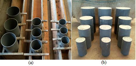
A total of 24 unconfined(plain) and Concrete-Filled Single Skin uPVC Tubular (CFSUT) specimens with different values of aspect ratio (h/D = 2,4 and 6), thickness to diameter ratio, and a concrete compressive strength of 25MPa was cast and tested to investigate the performance under axial compression loads as shown in Table 5, Fig. (2) and Fig. (5). The uPVC tube was prepared by cutting a uPVC tube having a diameter of D=110 and 140mm and by varying the height to diameter ratio (h/D=2, 4 and 6) as shown in Fig. (2a). Unconfined concrete cylinders (ASTM C39-12 and C496-11) and uPVC confined concrete columns were cast by filling the wet concrete mix in three layers and compacting till no bubbles are seen on the surface (BS EN 12390-2:2009). After 24 hours the specimens were labeled based on concrete strength class (C3=C25), uPVC diameter (P2=90mm, P3=110mm and P4=140mm) and height to diameter ratio (H1=(h/D=2), H2=(h/D=4), H3=(h/D=6), and H4=(h/D=8); for example, C3P3H3 means a confined concrete cylinder having a concrete strength of C25, uPVC diameter of 110mm and aspect ratio of six (h/D=6).
| Label | Concrete Class | Diameter (mm) | Thickness of uPVC Tube (mm) | Height of the Specimens (mm) | Number of Specimens |
|---|---|---|---|---|---|
| C3 | C25 | 100 | - | 200 | 3 |
| C3 | C25 | 110 | - | 220 | 3 |
| C3P3H1 | C25 | 110 | 3 | 220 | 3 |
| C3P4H1 | C25 | 140 | 3 | 280 | 3 |
| C3P3H2 | C25 | 110 | 3 | 440 | 3 |
| C3P4H2 | C25 | 140 | 3 | 560 | 3 |
| C3P3H3 | C25 | 110 | 3 | 660 | 3 |
| C3P4H3 | C25 | 140 | 3 | 840 | 3 |
2.3.2. Double Skin Concrete-Filled uPVC Tube
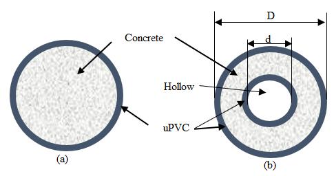
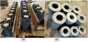
A total of 21 concrete-filled double skin uPVC tubular columns with C25, height to diameter ratio of (h/D =2, 4 and 6) and thickness of (D-d) = 53, 71 and 83mm were cast and tested as shown in Table 6, Figs. (3, 4 and 5). The columns were labeled based on the concrete strength class (C3=C25), thickness (D1= 53, D2=71 and D3=83) and aspect ratio of h/D =2, 4 and 6; For example, C3D1H2 means double skin with concrete class of C25, thickness (D-d) of 53mm and aspect ratio(h/D) of four.
2.4. Instrumentation, Test Setup and Loading Program
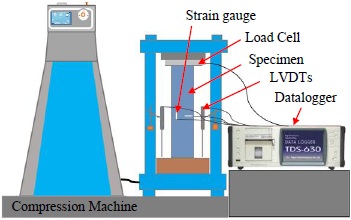
The instrumentation, test setup and loading program were completely described in the previous author's work [2], but are briefly discussed here for clarification purpose. After casting the specimens in water for 28 days, they were brought out from the water and the two sides of the specimens were smoothened using a concrete cutting machine to avoid a local buckling of the uPVC tube at the edge, and allowed to dry prior to testing as shown in Fig. (2b) and Fig. (4b). The test was performed using Compression Machine, which has a capacity of 2000kN and a testing frame with hydraulic loading jack connected to it as shown in Fig. (5). In addition, a load cell, transducers and strain gages connected to TDS-630 Datalogger were used to capture the measurements. First, the two strain gauges were placed on the surface of the specimen to measure the axial and radial strains. Then, the specimen was placed in between the two flattens of the compression testing machine, and also in between the upper and lower beam of the testing frame. Two LVDTs (Linear Variable Differential Transducers) were placed vertically, pointing to the moving plate of the machine to measure the axial deformation. After carefully placing the specimen in the testing machine, the strain gauges, load cells, and LVDTs were connected to TDS-630 data logger. The load was applied to the specimen at the rate of 0.2MPa/s till failure. The data was recorded both from the compression machine (Load-time data, Max. Load & Max. Strength) and TDS-630 Datalogger (time, Load, axial strain, radial strain, & displacement).
| Label | Concrete Class | D (mm) | d (mm) | Height, h (mm) | Number of Specimens |
|---|---|---|---|---|---|
| C3D1H1 | C25 | 110 | 57 | 220 | 3 |
| C3D2H1 | C25 | 140 | 69 | 280 | 3 |
| C3D3H1 | C25 | 140 | 57 | 280 | 3 |
| C3D1H2 | C25 | 110 | 57 | 440 | 3 |
| C3D3H2 | C25 | 140 | 57 | 560 | 3 |
| C3D1H3 | C25 | 110 | 57 | 660 | 3 |
| C3D3H3 | C25 | 140 | 57 | 840 | 3 |
3. RESULTS AND DISCUSSIONS
3.1. Failure Modes
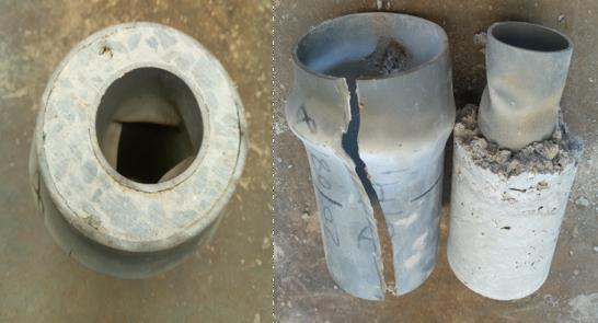
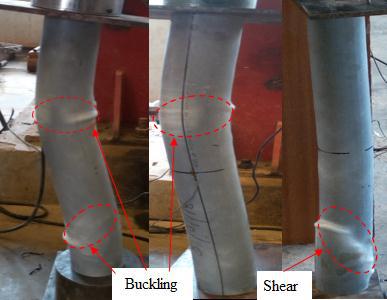
The failure modes of single and double skin concrete filled uPVC tube specimens are shown in Figs. (6, 7 and 8). In contrast to the un-confined ones , all the confined (single and double skin) specimens showed a ductile failure. The Concrete-Filled Single Skin uPVC Tubular (CFSUT) specimens experienced drum, shear and buckling type failure. Different types of failure progression were observed in Concrete-Filled Double Skin uPVC Tubular (CFDUT) specimens, which are outward expansion making a drum type failure with local buckling of internal uPVC tube. Fig. (6a) shows the drum and shear-type failure modes of single skin concrete filled uPVC tube specimens. Drum type failure mode is the most prevalent type of failure observed during the experiment. The drum type failure mode is due to the type 2 and 3 failure modes (ASTM C39/C39M − 15a) of the core concrete. The shear-type failure mode was a observed event. The diagonal cracks of the concrete due to type 4 failure (ASTM C39/C39M − 15a) created the shear-type failure. Further loading the specimen pushed the two halves in the opposite direction on the inclined plane, creating a bump like structure. Fig. (7) shows the failure mode of double skin concrete filled uPVC tube specimens. The specimen expanded outside similar to the single skin creating drum-type failure. The internal tube has undergone local buckling (Fig. 7). Buckling type failure mode was observed for higher aspect ratios for both single and double skin concrete filled uPVC tube specimens (Fig. 8).
3.2. Strength and Strain Enhancement Ratio
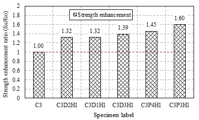
Figs. (9 and 10) show the strength and strain enhancement ratio of unconfined concrete and single and double skin concrete-filled uPVC tube specimens. For both single and double skin specimens, the strength increased by more than 30% compared to the unconfined specimens. Similar researches that were done on single skin concrete-filled uPVC tube equivalent cylinders by Woldemariam et al. [2] showed that the strength enhancement ratio ranged was between 1.28 and 2.35 for different concrete strength and pipe size. Fig. (10a) shows the strain enhancement ratio of single skin and double skin concrete filled uPVC tube specimens at the peak load. For single and double skin specimens, the strain at peak load increased by more than 3 times compared to the unconfined specimen. Fig. (10b) shows the strain enhancement ratio of single and double skin at the failure load. It was observed that the strain at failure load increased by more than 9 times compared to the unconfined specimens.

 .
.3.3. Effect of Hollow Size
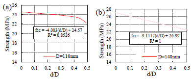
The recorded axial strength of concrete filled double skin uPVC tubular (CFDUT) specimens is presented in Table 7, Figs. (11 and 12). The axial strength of (CFDUT) was obtained by testing the specimen under axial compression and compared with concrete filled single skin uPVC tubular (CFSUT) specimens. Figs. (11 and 12) show the relationship between the strength of single and double skin concrete-filled uPVC tube. For single skin, two types of uPVC tube size with a thickness of 3mm and a diameter of 110 and 140mm were used to prepare the specimens. The strength of (CFSUT) specimens were 26.99 and 24.57MPa. The strength decreased as the 2t/D ratio increased. The double skin specimen (CFDUT) was prepared from two uPVC tubes of the same height and different diameter where concrete is sandwiched in between the two tubes, as shown in Fig. (3b). To study the effect of hollow ratios on the axial strength, two different diameters of outer tubes (110 and 140mm) and inner (63 and 75mm) were used to prepare the specimens. The strength of the specimens decreased as the hollow ratio (d/D) increased.

 , (b) at failure
 .
.
| Internal Tube | Ext. Tube | ||||||||||
|---|---|---|---|---|---|---|---|---|---|---|---|
| Label | t1 | D1 | d | t | D | h | h/D | D/h | (D-d)/D | Strength (MPa) | |
| C3P3H1 | 0 | 0 | 0 | 3 | 110 | 220 | 2 | 0 | 1 | 26.99 | |
| C3P4H1 | 0 | 0 | 0 | 3 | 140 | 280 | 2 | 0 | 1 | 24.57 | |
| C3P3H2 | 0 | 0 | 0 | 3 | 110 | 440 | 4 | 0 | 1 | 24.59 | |
| C3P3H3 | 0 | 0 | 0 | 3 | 110 | 660 | 6 | 0 | 1 | 23.15 | |
| C3P3H4 | 0 | 0 | 0 | 3 | 110 | 880 | 8 | 0 | 1 | 20.98 | |
| C3D1H1 | 3 | 63 | 57 | 3 | 110 | 220 | 2 | 0.52 | 0.48 | 22.27 | |
| C3D2H1 | 3 | 75 | 69 | 3 | 140 | 280 | 2 | 0.49 | 0.51 | 22.29 | |
| C3D3H1 | 3 | 63 | 57 | 3 | 140 | 280 | 2 | 0.41 | 0.59 | 23.49 | |
| C3D1H2 | 3 | 63 | 57 | 3 | 110 | 440 | 4 | 0.52 | 0.48 | 20.14 | |
| C3D1H3 | 3 | 63 | 57 | 3 | 110 | 660 | 6 | 0.52 | 0.48 | 18.37 | |
| C3D3H2 | 3 | 63 | 57 | 3 | 140 | 560 | 4 | 0.41 | 0.59 | 20.71 | |
| C3D3H3 | 3 | 63 | 57 | 3 | 140 | 840 | 6 | 0.41 | 0.59 | 18.43 | |


Woldemariam et al. [2] have developed an analytical expression for concrete-filled single skin uPVC tube equivalent cylinders that relates the concrete strength, tensile strength, diameter, and thickness of the confining material as shown in Eq. (1):
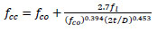 |
(1) |
An expression for double skin concrete-filled uPVC tube equivalent cylinder was developed based on Figs. (11 and 12) and Eq. 1. The results on two different 2t/D and three d/D ratios are used to define the relation in Eq. 2 and 3.
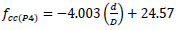 |
(2) |
|
(3) |
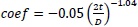
From the above two equations (Eq. 2 and 3), the two constants are equal to the peak strength of (p=90 &110mm) concrete filled single skin uPVC tubular specimens with h/D =2 and can be calculated by the expression in Eq. 1. The coefficients (coef 1 = -4.0003 & coef 2 = -9.1117) are dependent on 2t/D.
Thus, the strength of double skin concrete-filled uPVC tube specimen can be calculated by the expression in Eq. 4.
 |
(4) |
3.4. Effect of Aspect Ratio
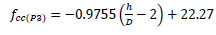
Fig. (13) shows the effect of aspect ratio (h/D) on strength. The strength decreased as the aspect ratio increased. An expression to predict the strength of double skin concrete filled uPVC tube specimens for different aspect ratios is developed. As the aspect ratio (h/D) increased from 2 to 6, the peak strength decreased, as shown in Fig. (13) and Table 7. The results of two different 2t/D and three h/D ratios are used to define the relation shown in Eq 5.
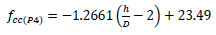 |
(5) |
 |
(6) |
From the above equation (Eq. 5 and 6), the two constants are equal to the peak strength of (p=90 &110mm) double skin concrete-filled uPVC tube with h/D =2 in Eq. 4. The coefficients (coef 1= -1.2661 & coef 2= -0.9755) are dependent on 2t/D. Hence,
 .
.
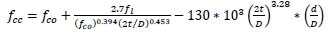
The general equation in Eq 7. was developed by combining Eq. 4, Eq. 5, and Eq. 6.
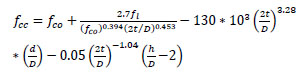 |
(7) |
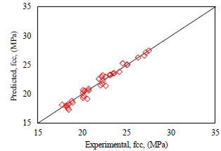
The model in Eq. 7 was used to predict the peak strength, compared with the experimental result (Fig. 14). The accuracy of the model was evaluated by using an Average Absolute Error (AAE), as defined in Eq. 8. The proposed model predicted the peak strength reasonably well with an AAE of 2.13%.
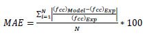 |
(8) |
3.5. Axial Stress-strain Behavior
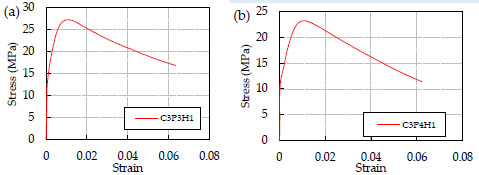
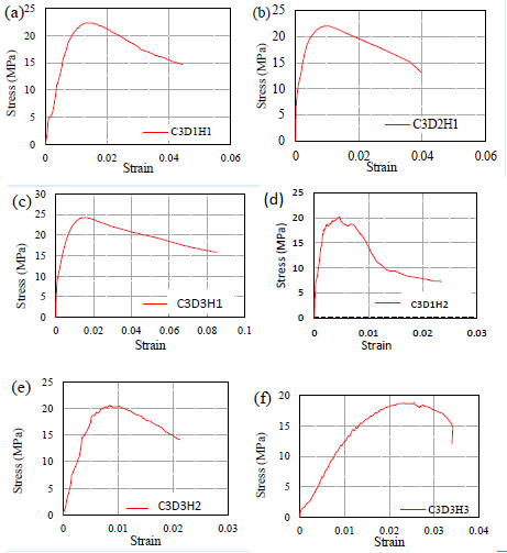
Fig. (15) shows the stress-strain behavior of unconfined concrete equivalent cylinders. The unconfined specimen has undergone a brittle failure after reaching the peak strength whereas both the single and double skin specimens have undergone a ductile failure without a sudden strength loss. Figs. (16 and 17) show the stress-strain curve of single and double skin concrete-filled uPVC tube specimens under axial compression load. The result shows that both single and double skin have exhibited similar behavior. When the h/D ratio was increased from 2 to 6, the specimens exhibited a post-peak displacement softening with a strength loss, as shown in Fig. (17e, f).

3.5.1. Ductility and Energy Absorption
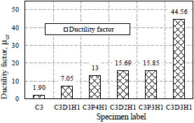
Fig. (18) shows the parameters used to calculate the ductility factor and energy absorption. The ductility factor is the ratio of strain at fracture strength to strain at maximum elastic strength [36-39] and it was calculated by the expression given in Eq. 9. Fig. (19) and Table 8 demonstrates the results on the ductility factor of unconfined concrete, single skin and double skin concrete-filled uPVC tube specimens. For single and double skin specimens, the ductility factor increased by 3.7 to 23.45 times compared to the unconfined concrete specimens.

| Label | fco | fcc | εco | εcc | ε1 | εcr | fcc/fco | εcc/εco | μcr | E |
|---|---|---|---|---|---|---|---|---|---|---|
| C3 | 16.89 | 0.0029 | 0.0017 | 0.0033 | 1.89 | 0.038 | ||||
| C3P3H1 | 26.99 | 0.0098 | 0.0033 | 0.0515 | 1.60 | 3.43 | 15.85 | 1.14 | ||
| C3P4H1 | 24.57 | 0.0094 | 0.0050 | 0.0650 | 1.45 | 3.32 | 13.00 | 1.11 | ||
| C3P3H2 | 24.59 | 0.0331 | 0.0060 | 0.10000 | 1.02 | 10.18 | 16.67 | 1.99 | ||
| C3P3H3 | 23.15 | 0.0175 | 0.0060 | 0.06580 | 0.96 | 5.40 | 30.54 | 1.18 | ||
| C3P3H4 | 20.98 | 0.0187 | 0.0055 | 0.08600 | 0.87 | 5.76 | 16.23 | 1.29 | ||
| C3D1H1 | 22.27 | 0.0130 | 0.0065 | 0.0458 | 1.32 | 4.56 | 7.05 | 0.79 | ||
| C3D2H1 | 22.29 | 0.0090 | 0.0020 | 0.0314 | 1.32 | 3.16 | 15.69 | 0.59 | ||
| C3D3H1 | 23.49 | 0.0130 | 0.0020 | 0.0891 | 1.39 | 4.56 | 44.56 | 1.73 | ||
| C3D1H2 | 20.14 | 0.0045 | 0.0015 | 0.0234 | 1.19 | 1.56 | 15.61 | 0.29 | ||
| C3D1H3 | 18.37 | 0.0124 | 0.0044 | 0.0151 | 1.09 | 4.35 | 3.43 | 0.21 | ||
| C3D3H2 | 20.71 | 0.0084 | 0.0040 | 0.0247 | 1.23 | 2.95 | 6.17 | 0.39 | ||
| C3D3H3 | 18.43 | 0.0255 | 0.0130 | 0.0340 | 1.09 | 8.94 | 2.62 | 0.47 |
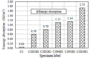
The energy absorption is the area under the stress-strain curve [36, 38-41] and it was obtained by integrating the stress-strain curve (see Eq.10). Fig. (20) and Table 8 shows the results on the energy absorption capacity of unconfined concrete, single and double skin concrete-filled uPVC tube specimens under axial compression loads. The energy absorption capacity of single and double skin specimens increased by 14.75 to 43.25 times compared to the unconfined concrete specimens.
 |
(9) |
 |
(10) |
CONCLUSION
This paper has presented the results on the behavior of single and double skin concrete-filled uPVC tube specimens subjected to axial compression loads. The following conclusions are drawn based on the results reported in this paper.
- Both single and double skin concrete-filled uPVC tubular specimens exhibited very ductile behavior under axial compression load compared to the unconfined concrete specimens. For concrete-filled single and double skin uPVC tubular specimens, the strength, ductility, and energy absorption increased by more than 1.32, 3.75 and 14.75 times compared to the unconfined concrete specimens, respectively.
- The failure modes observed during the experimental program were the brittle crushing, drum, shear, and buckling type failure modes. The unconfined concrete has undergone a brittle failure. Drum type failure mode is the most prevalent failure modes observed in both single and double skin specimens with lower aspect ratios. For double skin specimen, the specimen expanded outward similar to the single skin creating drum-type failure. The internal tube of double skin specimen has undergone local buckling. Also, buckling type failure mode was observed on both CFSUT and CFDUT specimens with higher aspect ratios.
- As expected, the use of uPVC tube in single and double skin concrete-filled tubular specimens increased the strength. The strength of CFDUT decreased as the hollow ratio (d/D) and aspect ratio (h/D) increased.
- The peak strength and strain enhancement ratios
 of CFSUT and CFDUT increased by 1.32 and 3.16 times compared to the unconfined respectively.
- The peak strength model predicted the peak strength of axially loaded concrete-filled uPVC tube column with a mean absolute error of 2.13%.
Ductile behavior with improved strength of concrete filled single and double skin uPVC tubular system has been observed during the study. The concrete-uPVC tube hybrid system has the potential to be used for building columns, bridge piers, highway head structures, piles, electric and telecom poles. However, more work is required on uPVC confined concrete columns under eccentric, lateral, cyclic and pure bending load to further understand its performance under different loading conditions.
NOMENCLATURE
AUTHOR CONTRIBUTIONS
Author Contributions: Conceptualization, A.M.W., W.O.O. and T.N.; Methodology, A.M.W., W.O.O. and T.N.; Experiment and data collection, A.M.W.; software, A.M.W.; Analysis, A.M.W.; writing-original draft preparation, A.M.W.; writing-review and editing, A.M.W., W.O.O. and T.N.
CONSENT FOR PUBLICATION
Not applicable.
AVAILABILITY OF DATA AND MATERIALS
The data that support the findings of this study are available from the corresponding author upon request.
FUNDING
Material support from the African Union Commission (AUC) and Africa-ai-Japan Project 2018-2019 to carry out the experiment is gratefully acknowledged.
CONFLICT OF INTEREST
The authors declare no conflict of interest, financial or otherwise.
ACKNOWLEDGMENTS
The authors sincerely thank the African Union Commission (AUC) and Africa-ai-Japan Project for funding this research.

