All published articles of this journal are available on ScienceDirect.

Innovative Structural Solutions for Prefab Reinforced Concrete Hall-Type Buildings
Abstract
Background:
The anti-seismic design of prefab reinforced concrete buildings is usually carried out with a conventional ductility-based approach. This implies a remarkable plastic demand on columns, as well as damages to the connections of structural and non-structural members, for seismic events with comparable intensity to the basic design earthquake normative level.
Objective:
In view of this, a study was developed and aimed at extending to the field of new prefab reinforced concrete structures the application of advanced seismic protection strategies, capable of guaranteeing undamaged response up to the maximum considered earthquake normative level.
Method:
A benchmark building was designed as demonstrative case study for this purpose, in the three following hypotheses: (a) according to a traditional ductility-based approach; (b) by incorporating dissipative bracings, equipped with fluid viscous dampers; (c) by placing a seismic isolation system at the base, composed of a set of double curved surface sliders.
Results:
The results of the verification analyses show that the targeted performance for the design solutions b) and c) is obtained with sizes of columns and plinths notably smaller than those for the conventional design. This allows compensating the additional cost related to the incorporation of the protective devices, for the dissipative bracing system, and limiting additional costs below 25%, for the base isolation solution. At the same time, a supplemental benefit of the latter is represented by greater protection of contents and plants, as they are fully supported by the seismically isolated ground floor.
Conclusion:
The study highlights the advantages offered by the two advanced seismic protection technologies in an unusual field of application, guaranteeing an enhanced performance of structural and non-structural elements, as well as reduced member sizes, as compared to the traditional ductility-based design.
1. INTRODUCTION
The traditional ductility based on anti-seismic design of prefab reinforced concrete (R/C) buildings implies remarkable plastic demand on columns, as well as severe distortions in the connections of structural and non-structural members, for input motions scaled at the Basic Design Earthquake (BDE) normative level. This causes considerable economic losses, due to the damage suffered by the buildings and the prolonged interruption of the activities carried out inside them, especially when they have industrial, manufacturing or commercial intended use. In the case of strategic prefab buildings, such as fire stations, civil defense headquarters, hospitals, airport and port terminals, etc., seismic damage to structural members and non-structural damage should be prevented to the minimum. Indeed, for these buildings the attainment of the Immediate Occupancy (IO) performance level is normally requested up to the BDE. As a consequence, if a conventional design approach is adopted, the resulting size of all members, particularly of columns and the connecting links of structural elements (roof purlins and tiles, girders, beams, stairs and foundations), as well as of non-structural components (cladding and internal panels, traveling cranes, gutters and plants), tend to grow significantly.
An improvement in the substantial performance of ordinary prefab buildings, aimed at preventing post-quake interruptions in use for moderate seismic events, as well as a remarkable limitation of member size for strategic structures, when targeting an IO-BDE design objective, can be attained by incorporating advanced motion control-based design solutions, based on the dual concepts of supplemental energy dissipation or seismic isolation. Both design strategies have been applied to the seismic retrofit of existing prefab buildings, especially after the earthquakes severely damaged large stocks of these buildings in the Mediterranean area over the last decade. At the same time, very few real [1] or simulated applications [2, 3] are reported for new buildings, limitedly to dissipation techno- logies.
In view of this, a study was recently undertaken by the authors, aimed at extending to the field of new prefab R/C buildings the application of advanced seismic protection strategies, addressed at previous steps of the same research line to the new design [4-7] or retrofit [8-12] of R/C and steel frame structures, and to the retrofit of prefab R/C structures [13] and special installations and infrastructures [14-16]. A benchmark building was specially designed for this purpose by assuming the typical geometrical layout and dimensions of single hall-type R/C prefab buildings in Italy, which are also similar to the characteristics of the same class of buildings in other Mediterranean countries. The design was carried out in the three following hypotheses: (a) according to a traditional ductility-based normative approach; (b) incorporating dissi- pative bracings, equipped with fluid viscous dampers; (c) placing a seismic isolation system at the base, composed of a set of double curved surface sliders.
The earthquake and performance levels assumed, their relevant limitations, the pre-sizing criteria and technical specifications adopted for the three design solutions, as well as a comparison of the final member sizes, their seismic response capacities and corresponding costs, are detailed in the follow- ing sections.
2. METHODS
2.1. Geometrical and Structural Characteristics of the Building
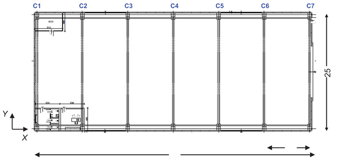
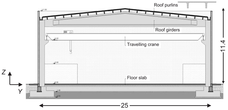
The geometrical plan of the building, identical for the three design hypotheses, and a transversal cross-section referred to the traditional design solution, are shown in Figs. (1 and 2), respectively, where the reference X, Y and Z axes of the Cartesian coordinate system adopted in the analyses are also traced out.
As highlighted in the drawing of Fig. (1), the plan is rectangular, with external sides of 61 m in longitudinal direction, parallel to X, and 25 m in transversal direction, parallel to Y. As mentioned above, the structure is a single-hall type, constituted by 14 R/C prefab columns, numbered C1 through C14 in Fig. (1), and 7 triangle-shaped pre-stressed prefab R/C girders (Fig. 2), with cross section base of 400 mm and height varying from 1020 mm to 2270 mm. The column alignments are placed at a mutual distance of 10 m. The height of the roof-top from the ground level is equal to 11.4 m. The roof is made of a set of pre-stressed R/C purlins with 400 mm high “π”-shaped section, composed of two 320 mm high webs, 100 mm wide at the bottom and 110 mm wide on top, and an 80 mm thick upper slab. An additional 50 mm thick upper R/C slab is cast on-site, so as to obtain a rigid diaphragm function of the roof with respect to wind and seismic forces. Purlins are fastened to the supporting girders by means of bolted steel joints. V channel-type prefab beams connect the top sections of the columns in the X direction on both sides of the building.
Purlins, girders and longitudinal V beams are mutually adopted, with same dimensions and reinforcement details, for the three design solutions developed in this study, as they are independent of the specific seismic design strategy adopted for the vertical structure.
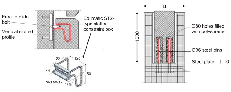
Each column includes a corbel supporting a longitudinal continuous steel beam bearing the overhead travelling crane, with a maximum allowable load of 160 kN. The cladding panels are constituted by 200 mm thick prefab R/C slabs incorporating a 100 mm thick insulation sheet. The panels are joined to the columns by patented steel boxes [17], shown in Fig. (3), with pinned-type slotted connections capable of accommodating maximum horizontal drifts equal to 2.75% of the panel height, at their horizontal ends; and to a continuous R/C foot edge-beam, at their bottom end. The pinned connections of the panels simply transfer their self weight to the joined columns, but do not allow the panels to contribute to the lateral stiffness of the building. Consequently, the presence of the panels is simulated in the finite element analyses only in terms of dead loads and corresponding seismic inertial masses, with no structural interactions with the columns.
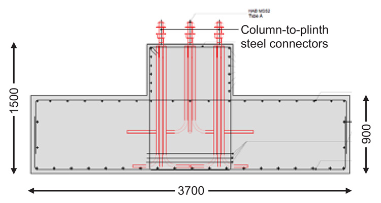
A transversal cross-section of the girder-to-column connection is illustrated also in Fig. (3), where the geometrical and technical details are equal for the three designs, except for the column size (denoted with symbol B in the drawing, which varies case by case). Two Ø 36 steel pins emerging from the column top, acting as dowel restrainers, are inserted in vertical cylindrical slots with diameter of 140 mm, located in the terminal zone of the girder, to prevent any possible loss of support of the latter from the column, in case of high relative displacement demands. The holes are filled with compressible polystyrene to protect the steel pins against moisture effects, without hindering the free relative displacements between girder and column.
Each end zone of girders includes a square bearing pad placed at its intrados in the manufacturing phase, constituted by a 10 mm-thick steel plate sized (400×400) mm2, with two central holes for the connection to the girder vertical slots.
The dead plus live gravitational loads distributed on the girders are equal to 39 kN/m. Concrete used for the prefabricated columns is class 45/55, with characteristic compressive cylindrical strength, fck, equal to 45 MPa, and characteristic compressive cube strength, fck,cub, equal to 55 MPa; concrete for the on-site cast foundation plinths is class 32/40 (fck=32 MPa, fck,cub=40 MPa). Steel is B450C type, with nominal yield stress, fy,nom, equal to 450 MPa, and strength, fu,nom, equal to 540 MPa. Concrete for the pre-stressed prefabricated girders and purlins is class 50/60 MPa (fck=50 MPa, fck,cub=60 MPa). The characteristic values of strength, fptk, nominal yield stress at 0.1 residual strain, fp(0.1)k, and stress at 1% of total strain, fp(1)k, of the harmonic steel constituting the strands of purlins and girders are equal to 1860 MPa, 1600 MPa and 1670 MPa, respectively.
2.2. Earthquake Design Levels
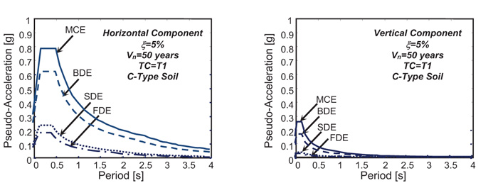
The three designs were carried out for the four reference seismic levels fixed in the Italian Standards [18], that is, Frequent Design Earthquake (FDE, with 81% probability of being exceeded over the reference time period VR); Serviceability Design Earthquake (SDE, with 63%/VR probability); Basic Design Earthquake (BDE, with 10%/VR probability); and Maximum Considered Earthquake (MCE, with 5%/VR probability). The VR period is fixed at 50 years. By referring to topographic category T1 (flat surface), and C-type soil (deep deposits of dense or medium-dense sand, gravel or stiff clay from several ten to several hundred meters thick), the resulting peak ground accelerations for the four seismic levels referred to the site of the building are as follows: 0.075 g (FDE), 0.096 g (SDE), 0.254 g (BDE), and 0.313 g (MCE), for the horizontal motion components; and 0.015 g (FDE), 0.022 g (SDE), 0.1 g (BDE), and 0.151 g (MCE), for the vertical component. Relevant elastic pseudo-acceleration response spectra at the linear viscous damping ratio ξ of 5% are plotted in Fig. (4).
In the traditional design hypothesis, the sizing analyses were developed by scaling the spectra referred to the BDE and the MCE by a behaviour factor q=2.5, as admitted by Italian Standards [18] for partly/completely prefabricated structures complying with ductility class “B” requirements, with fixed base columns having hinged connections to the girders. The same spectra were not scaled (q=1) for the DB-based and BI-based design solutions, because an undamaged elastic structural response was pursued up to the MCE in both options. The FDE and SDE-related elastic response spectra were mutually assumed for the three design hypotheses.
Final verification time-history analyses were developed by assuming artificial ground motions as inputs, generated in families of seven by SIMQKE-II software [19] from the elastic spectra above, both for the horizontal components (two families) and the vertical one (one family). In each time-history analysis, the accelerograms were applied in groups of three simultaneous components, i.e. two horizontal components, with the first one selected from the first generated family of seven motions, and the second one selected from the second family, plus the vertical component. The solution of the equations of motion was carried out with the average acceleration method of Newmark-beta family. A 0.005 s value of the integration time-step, Δt, was adopted throughout the analyses, so as to meet accuracy conditions for the numerical solution with wide margins.
2.3. Traditional Design Solution
2.3.1. Final Sizing of Structural Members-Modal Analysis
The outcome of the design process is synthesized in Figs. (5 and 6), where the vertical and mid-height cross sections of a column, and the cross-section of a foundation plinth, are shown. As illustrated by these drawings, columns have sections of 800×800 mm2 with 28 Ø20 reinforcing bars, and Ø12 stirrups spaced at 120 mm (bottom end zone) and 200 mm (remaining zones). Plinths have a square plan with sides of 3700 mm, bottom flange height of 900 mm, and the total height of 1500 mm. A set of ten steel connectors anchored in the plinths are screwed to ten corresponding nuts welded to special steel caps embedded in the columns, to obtain a monolithic plinth-to-column joint. A mesh of R/C beams sized (400×500) mm2 connects the 28 plinths, as requested by the Italian Standards to prevent possible differential displacements of their bases. These beams are included also in the two non-conventional design hypotheses.
The finite element model of the structure was generated by SAP2000NL program [20]. A perspective view of the model is displayed in Fig. (7).

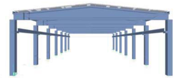
The mesh of the roof is made of shell-type elements; columns and longitudinal beams of frame-type elements; and girders of non prismatic frame elements, which allow precisely reproducing the variable section of these members. In view of the technical solution adopted for the plinth-to-column joint, a fixed-end constraint is introduced at the column bases.
A modal analysis was initially carried out by this model, which shows that the first mode is translational in X direction, with a vibration period of 1.377 s and effective modal mass (EMM) equal to 97.4%; the second mode is translational in Y direction, with a period of 1.364 s and EMM equal to 96.9%; and the third mode is rotational around the Z axis, with a period of 1.307 s and EMM equal to 97.7%. Therefore, the first three modes are sufficient to activate EMMs nearly equal to the total seismic mass of the building along the two horizontal axes and around the vertical one.
2.3.2. Time-History Verification and Performance Assess- ment Analysis
The time-history verification and performance assessment analysis of the building was carried out for the four normative seismic levels described above. For this analysis, the sliding contact between the steel plates placed below the terminal zones of the roof girders and the top of the columns was simulated by the “Friction Isolator” link element available in the library of SAP2000NL program. This is a stick-slip element with coupled friction properties for the deformations along the two reference local axes in plan, governed by a Coulomb-type hysteretic law, and “gap”-type (i.e. no tension) behaviour in vertical direction. The value of the friction coefficient, μ, was fixed by considering the results of experimental studies carried out on the sliding friction contact between steel and concrete surfaces [21], which highlighted μ values ranging from about 0.7 to about 0.3 in static (zero velocity) conditions, and from about 0.5 to 0.1 in dynamic response conditions. Like for any friction contact problem, these values are a function of the roughness of the facing surfaces and the normal stress acting on them. In the case examined here, the bearing plate is made of plain steel and the prefabricated columns of troweled and compacted concrete. The design compressive stress, equal to 4.7 MPa, is a standard design value for the bearing zones of prefab concrete members. Based on these design data and the suggestions of the above-mentioned experimental studies, the median values of relevant μ ranges, i.e. μ=0.5 for static conditions and μ=0.3 for dynamic response conditions, were adopted in the time-history analyses.
The results at the FDE and SDE levels are evaluated in terms of maximum drift ratio (i.e. the ratio of drift to height) of the cladding panels, drp. Peak drp values are equal to 0.25% (FDE) and 0.35% (SDE), far below the 0.66% limitation adopted by Italian Standards [17] at the Operational (OP) performance level for drift-sensitive non-structural elements not seismically interacting with the supporting structure, like the cladding panels in this design.
The response in the inelastic field is estimated by virtue of the “equal displacement rule” (i.e. the maximum deformation of the inelastic and the associated elastic systems may be considered the same). Indeed, it can be directly applied in this case since the three first vibration periods of the structure are included in the constant velocity branch of the horizontal pseudo-acceleration response spectrum, and relevant associated EMMs are nearly equal to 100% of the total seismic masses, as commented in Section 4.1. This allows considering the maximum drifts obtained from the elastic time-history analysis at the BDE and MCE as an acceptable approximation of the corresponding maximum inelastic drifts, thus providing a more general meaning to the seismic performance evaluation in terms of displacement response. The peak drp values at the BDE and the MCE are equal to 1.18% and 1.55%, respectively. Both values are greater than the IO-related limit of 1%, highlighting moderate (BDE) and medium (MCE) damage levels of panels (consisting in local fissures and cracks, dislocations and out of plumbs, etc.), as usually planned for the two highest earthquake levels in a conventional design. At the same time, even considering that these values could slightly underestimate the actual inelastic drifts, due to the inherent approximations of the “equal displacement rule”, they are far below the 2.75% drift capacity of the pinned slotted connections adopted for the panels. This allows to meet with wide margins the requirements of the Life Safety (LS) performance level for these elements, which are the most important non-structural components of the building, both from an architectural and an economic viewpoint. The performance in terms of bending-compression stress states of columns deduced from the results of the elastic time-history analysis is synthesized by a coefficient of exploitation, ρ (given by the ratio of the maximum combined biaxial bending moments to the corres ponding ultimate biaxial bending moment capacity computed for the design axial force), equal to 2.38 (BDE) and 3.13 (MCE), thus identifying a medium (BDE) and medium-to-high (MCE) potential plastic demand. By dividing ρ by the behaviour factor q=2.5, a value 0.95, i.e. very near to 1 (representing the normative nominal safety condition), is obtained at the BDE, as a consequence of the section size and column reinforcement optimizationplanned in the design analysis.
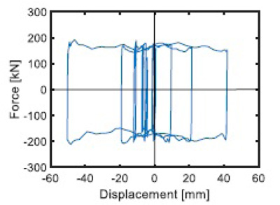
The response of the girder-to-column friction contact elements is assessed at the MCE, to check the consequences of the maximum relative displacements between the two members at the highest input seismic level. Fig. (8) shows the output cycles in the Y direction of the contact element for which the maximum displacements were noticed, situated between the steel plate of the girder borne by column 14 and the top section of the latter, as obtained from the most demanding MCE scaled group of input accelerograms.
The peak displacements highlighted by this graph are equal to about 50 mm, that is, below the 52 mm-wide available gap existing, in any direction, between the Ø 36 steel dowel restrainer and the corresponding cylindrical slot encased in the terminal zone of the girder, with 140 mm diameter. Therefore, no contact occurs between pins and slots up to the most demanding relative displacement response conditions.
The estimated total cost of the structure for this design hypothesis, not including plants and finishes, amounts to about 610,000 Euros, 335,000 of which represent the mutual cost of prefab girders, purlins, V-channel beams and cladding panels for the three design solutions.
3. RESULTS AND DISCUSSION
3.1. Design Solution Incorporating a DissiPative Bracing (DB) System Equipped With Fluid Viscous Dampers
3.1.1. Characteristics and Design of the DB System
The Dissipative Bracing (DB) system considered for this second solution, originally proposed by the authors both for new design and seismic retrofit of frame structures [6, 8-10], belongs to the class of viscous dissipative technologies, increasingly emerging in the field of passive protection strategies [22-50]. As observed in the Introduction, the application of this system to new prefab R/C buildings is explored for the first time within the study reported here.
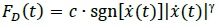
The Fluid-Viscous (FV) spring-dampers mounted in the DB system, detailed in previous studies [4], produce their damping action by means of a compressible silicone fluid flowing through the thin space found between the piston head and the internal casing. The FD(t) damping and Fne(t) non-linear elastic reaction forces corresponding to the damper and spring functions of the devices are effectively simulated by the following analytical expressions [4, 23]:
 |
(1) |
 |
(2) |
where t = time variable; c = damping coefficient; sgn(·) = signum function; x(t) =device velocity; |·|=absolute value; γ=fractional exponent, ranging from 0.1 to 0.2 [4]; F 0=static pre-load force; k1, k2=stiffness of the response branches situated below and beyond F 0; and x(t)=device displacement.
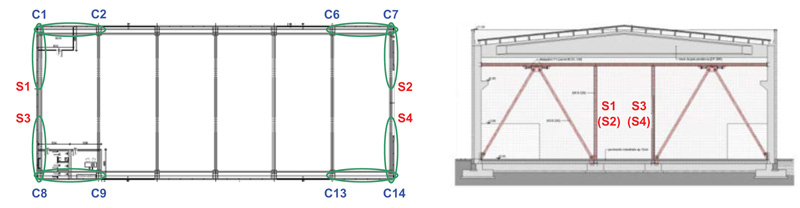
As shown by the building plan in Fig. (9), the dissipative braces are placed in four alignments parallel to X and four alignments parallel to Y. The X-parallel alignments are constituted by the four corner pairs of adjacent columns (C1-C2, C6-C7, C8-C9, C13-C14). Concerning the Y-parallel alignments, because the girder span is about 25 m long, four columns made of HEB 220 steel profiles, named S1 through S4 in Fig. (9), are added at a distance of 10 m from columns C1, C7, C8, and C14, prior to mounting the bracing members. This allows obtaining in Y the same brace span determined by the mutual distance of columns in X direction, while preserving a 5 m wide free central span for vehicle access.
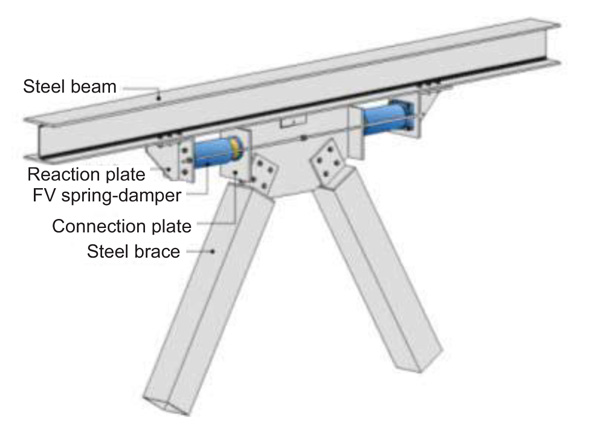
The installation layout of the FV springs-dampers, illustrated in Fig. (10), is similar to the basic configuration adopted for frame buildings. The only difference is that, to simplify mounting operations, the FV devices are connected in this case to an additional steel profile placed below the roof girders, in X. At the same time, in Y direction they are directly linked to the V channel-type prefab beams.
For the development of numerical analyses, the finite element model of FV spring-dampers is obtained by combining in parallel a non-linear dashpot element and a non-linear spring element with reaction forces given by (1) and (2), respectively [8, 9]. Both types of elements are currently incorporated in commercial programs, such as the SAP2000NL code used in this study. The complete finite element model of the structure including the protective system is displayed in Fig. (11).

The design of the FV devices was developed by the general criterion formulated in a previous study [8], which consists in assigning the installed devices the capability of dissipating a prefixed energy fraction, Ed,t, of the seismic input energy computed by the finite element model of the structure, Ei,t. For the examined building, an elastic response was targeted up to the maximum considered earthquake, to prevent damages to the structural and non-structural elements. In order to reach this objective, by referring to the suggestions formulated for frame structures [8-10], Ed,t was tentatively fixed at 85% of Ei,t calculated for the response to the MCE-scaled input action. The Ed,t demand estimated by this criterion was met by a set of medium-sized FV spring-dampers in current production [51], characterized by a nominal energy dissipation capacity, En, equal to 50 kJ, and a stroke, xmax, of ±65 mm (i.e. 65 mm in tension and 65 mm in compression). The supporting diagonal braces are made of 200 mm square tubular steel profiles with thickness of 8 mm.
3.1.2. Final Sizing of Structural Members–Modal Analysis
The final sizing of columns and plinths in the presence of the DB system is highlighted by the drawings in Fig. (12).
Columns have sections of 600×600 mm2 and are reinforced by 24 Ø20 bars, with Ø12 stirrups spaced at 150 mm (bottom end zone) and 250 mm (remaining zones). Plinths have square plan with sizes of 2600 mm, bottom flange height of 600 mm, and total height of 1100 mm. The resulting concrete volume of columns and plinths is approximately equal to half of the volume obtained for the traditional design solution; the quantity of reinforcement is reduced by about 15%.
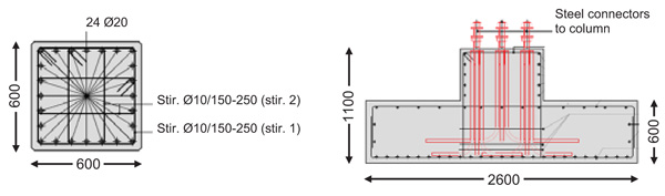
Based on the outcome of the design process, a new modal analysis was carried out with the finite element model of the structure including the DB system, which shows the same sequence of modes observed for the traditional design, i.e. a first translational mode in X, with a period of 1.885 s and EMM equal to 97.3%; a first translational mode in Y, with period of 1.828 s and EMM equal to 97%; and a first rotational mode around the vertical axis, with period and EMM of 1.644 s and 97.6%. The increase of periods is caused by the remarkable reduction of column size, negligibly counterbalanced by the stiffening effect of the dissipative braces. Indeed, the technical installation of FV spring-dampers and steel braces, which corresponds to an in-series rheological scheme, determines a relatively small horizontal translation stiffness of the DB system in dynamic response conditions, as it is essentially determined by the very low second-branch spring stiffness of the devices, k2. Consequently, this causes a little increase inthe horizontal stiffness of the structures where the system is incorporated.
3.1.3. Time-History Verification and Performance Assess ment Analysis
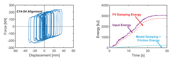
The total reaction force displacement [(Fd(t)+Fne(t)]–x(t) cycles of the pair of FV dampers installed in C14-S4 alignment, obtained from the most demanding MCE-scaled group of input motions, are visualized in the graph on the left in Fig. (13). The response cycles exhibit peak displacements equal to about 38 mm, i.e. no greater than 0.6 times the available positive and negative stroke limit of 65 mm mentioned above. Similar results come out for the other alignments and the other input accelerograms. The energy time-histories plotted in the graph on the right in Fig. (13) assess that the energy dissipated by the FV elements is nearly equal to the targeted 85% of the input energy.
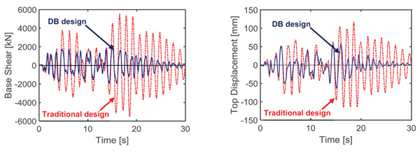
The base shear and top displacement time-histories ob- tained in Y direction from the most demanding MCE-scaled group of input motions, displayed in Fig. (14), highlight a reduction factor of about 3.2 (peak base shears) and 2.6 (peak top displacements) when passing from the traditional to the DB-based design.
The drop in base shear produces a corresponding decrease of the stress states in columns, determining their elastic response up to the MCE, as targeted in this design. Consistently, the maximum ρ value at the MCE results to be equal to 0.97. The reduction of top displacements leads to peak drift ratios of panels equal to 0.45% and 0.6% at the BDE and MCE, respectively. Both values are below the 0.66% OP-related drift limit, which means that no damage of panels is expected up to the MCE.
The estimated total cost of the structure amounts to about 627,000 Euros, that is, 2.8% greater than the cost of the conventional design.
3.2. Design Solution Incorporating a Base Isolation (BI) System Equipped With Double Curved Surface Sliding Bearings
3.2.1. Characteristics and Design of the BI System
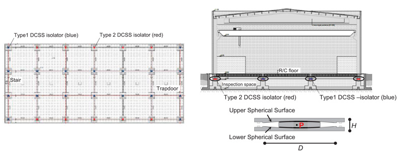
The proposed system includes double curved sliding surface (DCSS) bearings as isolation devices, which are extensively adopted in new designs, as well as in the retrofit of existing buildings, in Italy and several other earthquake-prone countries [7, 11, 12, 14, 52-61]. As shown by the schematic cross section in Fig. (15), they consist of two facing spherical concave surfaces, separated by an articulated double friction slider, which produces two independent pendulum response mechanisms.
The DCSS devices in standard production are charac- terized by identical properties of the two surfaces, and namely: radium R; slider center-to-surface distance h (i.e. the distance between the “pivot point” P of the articulated slider and the face of each spherical surface); effective pendulum length R-h (i.e. the distance between P and the center C of each surface, (Fig. (15); diameter of the horizontal projection of the spherical surface D; and friction coefficient μs. The resulting effective pendulum length LDCSS of the isolator is equal to twice the effective pendulum length of each surface, i.e. LDCSS =2·(R-h)=2R-2h.
The equivalent vibration period of a DCSS, Te, and the equivalent viscous damping ratio, ξe, are expressed as:
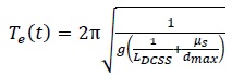 |
(3) |
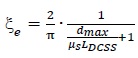 |
(4) |
where g=acceleration of gravity, and dmax=maximum displacement of the device along all directions in plan.
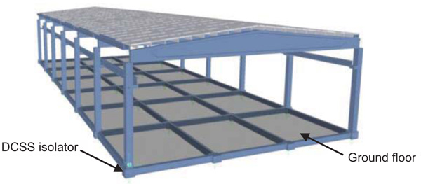
Based on a preliminary sizing carried out by computing the maximum axial force that each column transmits to the isolator placed below its base, and estimating the maximum displacement demand for the MCE seismic level, two types of DCSS devices were selected, named Type-1 (highlighted with blue symbols) and Type-2 (red symbols) in the plan and section of Fig. (15). The mechanical and geometrical properties of the isolators, as derived from the reference manufacturer’s catalogue [62], are as follows: LDCSS=3100 mm, dmax=±250 mm, μs=0.025, Te=3.1 s, ξe=15.2%, for both types; NRd=maximum allowable vertical force=1500 kN, D=540 mm, H=106 mm- Type-1; NRd= 2000 kN, D=570 mm, H=height=111 mm- Type-2. As illustrated by the plan in Fig. (15) and the detail drawing in Fig. (16), an R/C floor is built for this design solution at the ground level, to constitute a horizontal rigid diaphragm for the isolation system. The structure of the floor is made of “Predalles” type joists, with interposed lightening polystyrene blocks and a 50 mm thick on-site cast upper R/C slab. The span of the structure is subdivided in three equal portions by building two internal plinths per column alignment, over which a set of 14 Type-2 isolators is placed. Other 14 isolators are installed below the column bases (10 Type-1- perimeter columns, plus 4 Type-2- corner columns). In addition to constructing the floor, a perimeter retaining R/C wall is built around the structure, in order to accommodate the horizontal displacements of the base isolated structure, as well as to help easy inspection and maintenance of the fourteen devices situated at the feet of the columns, and the four placed below the floor along the two façade alignments. The ten internal isolators are accessed by six trapdoors inserted in the ground floor, each one giving access to two devices.

For the time-history verification analyses, the finite element model of the DCSS isolators was generated by the “Friction Isolator” link element available in the library of SAP2000NL code, i.e. a biaxial friction-pendulum element with coupled friction properties for the deformations along the two reference local axes in plan, and post-slip stiffness in both directions, as mentioned in Section 2.3.2. The complete finite element model of the structure including the base isolation system is shown in Fig. (17).
3.2.2. Final Sizing of Structural Members–Modal Analysis
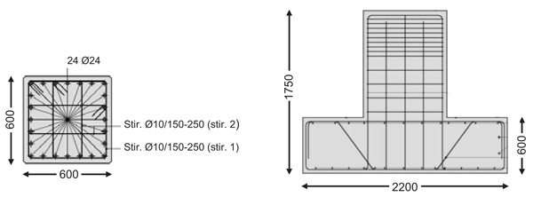
The final sizing of columns and plinths in the presence of the BI system is illustrated in Fig. (18). As shown there, columns have the same cross section dimensions as in the DB design- (600×600) mm2- and a slightly higher vertical reinforcement, in this case constituted by 24 Ø24 bars, instead of 24 Ø20 bars. The transversal reinforcement, consisting of Ø12 stirrups spaced at 150 mm (bottom end zone) and 250 mm (remaining zones), is identical.
Plinths have square plan with sizes of 2200 mm, bottom flange height of 600 mm, and total height of 1750 mm. The latter is adopted to guarantee the necessary underground height to carry out the required inspection and maintenance activities of the isolators. Like for the DB solution, the concrete volume of columns and plinths is approximately equal to half the volume obtained for the traditional design, whereas the quantity of reinforcement is reduced by about 12%.
The modal analysis for the BI design shows a first translational mode in X, with period of 3.294 s and EMM equal to 98.1%; a first translational mode in Y, with period of 3.212 s and EMM equal to 99%; and a first rotational mode around the vertical axis, with period of 3.131 s and EMM equal to 99.1%. The values of the two translational modes are slightly higher than the Te=3.1 s equivalent vibration period of the isolation system because of the deformability of the superstructure.
3.2.3. Time-History Verification and Performance Assessment Analysis
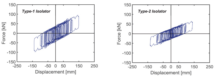
The force-displacement response cycles in X direction of a Type-1 isolator, situated under a corner column, and a Type-2 isolator, placed in central position, obtained from the most demanding MCE-scaled input accelerogram, are plotted in Fig. (19). A peak value of about 142 mm is recorded for both DCSS devices, far from the dmax=±250 mm displacement capacity of the isolators. The practically equal displacements of the two devices also highlight that the time-history response of the base isolated structure is virtually unaffected by plan torsion effects. The maximum base displacements in Y direction, not documented here for brevity’s sake, virtually coincide with the values obtained in X.
The base shear and top displacement time-histories obtained in Y direction from the most demanding MCE-scaled group of input motions, displayed in Fig. (20), highlight a reduction factor of about 3.5 on peak base shears and 1.9 on peak top displacements when passing from the traditional to the BI-based design.
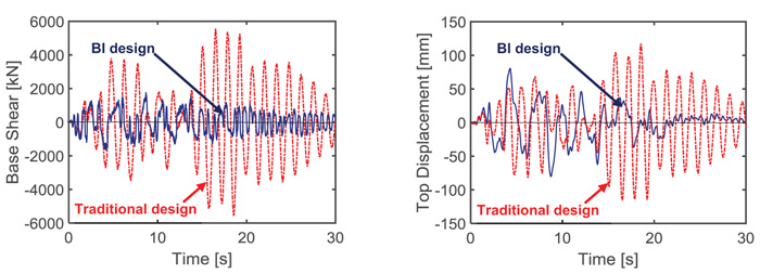
Like for the DB-based one, the drop of stress states in columns related to the reduction of base shear causes their elastic response up to the MCE, with a corresponding maximum value of the coefficient of exploitation ρ equal to 0.88 in this case. The maximum drp drift ratios of panels determined by the reduction of top displacements are equal to 0.62% at the BDE, i.e. below the 0.66% OP-related drift limit, and 0.81% at the MCE, below the 1% IO-related drift limit. Thus, no damage of panels is expected at the BDE for the BI-based design solution too, and a very slight and easy repairable damage at the MCE.
The estimated total cost of the structure amounts to about 764,000 Euros, that is, 25.2% greater than the cost of the conventional design, and 21.8% greater than the DB-based design. This increased amount is caused by the construction of the ground floor and the perimeter retaining wall, whose additional costs exceed the cost reduction of columns and plinths determined by the incorporation of the seismic isolation system.
It can be observed that the greater cost of the BI-based design would be fully motivated if a basement was built (to host plants, storage volumes, garages, etc.), instead of the underground space strictly required by the inspection and maintenance activities of the isolators. Indeed, in spite of a further additional cost of about 30,000 Euros related to a 1.2 m greater height of plinths and perimeter retaining wall needed to obtain a usable basement space, the latter would provide a significant economic and functional added value to the building. Furthermore, an additional benefit of the BI technology consists in the total protection of contents (machineries, scaffoldings, shelves, furnishes, etc.) and plants, whose economic value is often comparable to and sometimes even greater than the value of the building.
CONCLUSION
The dissipative bracing and base isolation design solutions developed for the case study prefab R/C building examined in this paper allow reaching an elastic structural response and an undamaged response of the cladding panels up to the maximum considered earthquake level, with columns and foundation plinths of significantly smaller sizes than in the ductility-based conventional design.
The extensive repair interventions required in the conventional design imply costs approximately equal to 30% and 50% of the original construction cost of the structure under seismic events with comparable intensity to the BDE, and the MCE, respectively. These data highlight the appropriateness of the two advanced designs, whose costs are virtually coinciding with the conventional solution (DB) or about 25% higher (BI). Additional costs related to the long interruption of usage of the building (and thus of the manufacturing and business activities housed in it), required to carry out the necessary post-quake repair works, must also be accounted for in the conventional design.
The installation layout of the FV springs-dampers incorporated in the DB system is similar to the basic configuration adopted for frame buildings, and their sizing criterion is the same. The high damping capacity of these dissipaters allows meeting the required seismic performance with a small number (eight pairs in total) of medium-sized devices in current production. The resulting eight DB system alignments are located at the four corners of the building, causing a null impact on the architectural plan. In view of this, the application of this dissipative bracing technology could be easily extended to other types of prefab R/C structures (e.g. with differently shaped girders and connection beams, with wider or smaller spans, for multi-storey and/or multi-span structures, etc.).
About 25% and 22% greater cost computed for the BI solution in comparison to the cost of the conventional and DB-based design, respectively, is caused by the construction of the ground floor and the perimeter retaining wall. Like for ordinary frame structures, this suggests adopting a base isolation system in hall-type prefab buildings when they include a basement. However, an additional benefit of the BI design, with respect to the dissipative bracing solution too, is represented by notably greater protection of contents and plants, as they are fully supported by the seismically isolated ground floor.
Based on these findings, the study carried out on the representative building examined here underlines the potential of the considered DB and BI technologies as alternative design strategies for hall-type prefab R/C buildings having similar characteristics.
CONSENT FOR PUBLICATION
Not applicable.
AVAILABILITY OF DATA AND MATERIALS
Not applicable.
FUNDING
Financial support from the ReLUIS-DPC Project 2019-2021 (Work Package 15: Normative Contributions for Isolation and Dissipation Project 9 – protocol nr. 60 - 05/02/2019– grant nr. 1100004434, 10.13039/50) is gratefully acknowledged.
CONFLICT OF INTEREST
The author declares no conflict of interest, financial or otherwise.
ACKNOWLEDGEMENTS
Declared none.

