All published articles of this journal are available on ScienceDirect.

Reuse of Ceramic Demolition Waste in the Reconstruction of Planked Timber Floor Slabs
Authors Info & Affiliations
Abstract
The aim of this work, mainly an experimental study, is to develop a new infill piece by reusing ceramic waste from demolition works. The piece is intended for use in floors as part of the rehabilitation of a type of building in which such materials were originally used, and forms part of the repair process of infill slabs characteristic of domestic architecture. It also enables the reuse of existing wooden beams that still retain their strength capacity.
Various test models to reproduce the geometry and structural characteristics of these slabs were developed, and experiments with the proportions of mortar and geometries were performed to achieve the required strength capacity for their use on site. As a result, an infill piece was produced with a strength capacity of up to 457 kgf, which exceeds the values required for prefabricated concrete slabs according to current regulations.
Finally, it should be noted that this new piece contributes to the conservation of the original vertical supporting structure based on masonry walls, while the horizontal structure is rendered lighter thanks to these new slabs.
1. INTRODUCTION AND BACKGROUND
The construction sector in Spain is currently experiencing a crisis as a result of environmental concerns in the building process. Constructed buildings are a direct cause of pollution in that they produce waste and consume large quantities of energy. Construction and demolition waste (CDW) is generated in the life-cycle of a building especially during the demolition and rehabilitation phases [1], so, any proposal for the rehabilitation of a building presumes significantly high levels of waste generation.
Of total waste generated in Mediterranean countries such as Spain, ceramic waste accounts for 54% of total demolition waste from construction [2]. The manufacture of ceramic products, such as coatings (both vertical and horizontal) and, to a lesser extent, the bricks and tiles, are the main components of this waste [3].
The increasing volume of such waste has led researchers to study the possibilities for its reuse. In Spain, the National Integrated Waste Plan (2008-2015 PNIR) has fomented demand for recycled CDW products, especially aggregates (Fig. 1). In recent years, several studies have tested the feasibility of applying this waste to the production of new materials and products by using it in the manufacture of concrete blocks [4-6], pavement slabs [7] or as subbase material for road construction [8]. Other studies are looking at the use of CDW in the manufacture of non-structural concrete infill, replacing natural aggregates with recycled material in various proportions [9].
The reused ceramic waste [10] mainly comes from manufactured tiles [11], sanitary pieces [12] or bricks [13-15]. This waste is ground into cement [16] as a form of cementsubstitute in the production of mortar [17, 18] or as an addition [13]. As for their use as aggregate in the form of a natural aggregate replacement, thicker fractions have been used as aggregates in concrete production [12, 14, 19] and the finer ones as recycled aggregate in mortar [15, 20].

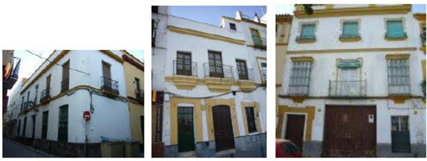
Researchers have so far focused on the use of ceramic waste as a recycled aggregate in the production of mortar or concrete, or as a cement substitute, mainly because of its pozzolanic properties. But none has investigated the use of ceramic tiles as a component for manufacturing slabs. This paper shows how ceramic waste can be reused to produce an infill piece for a planked timber slab system to rehabilitate typical domestic buildings constructed between the 17th and 20th century in southern Spain (Fig. 2).
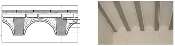
The planked timber floor slabs that are characteristic of this building typology consist of wooden beams with a curved infill that are traditionally packed with debris (alcatifa) and made on site (Fig. 3).
The aim of reusing ceramic tile demolition waste is to make a new piece that can be added to these slabs during their rehabilitation process. So, the waste generated in the demolition phase of the rehabilitation of these buildings forms part of the process of reconstruction and repair of the slabs of the original edifice. The development of this new piece enables us to reuse existing wooden beams that still have adequate strength capacity but their aesthetic is questionable since the proposed solution only exposes the underside of these beams. When we make a new piece of filled this is placed into the slabs as a non-loadbearing shuttering since these blocks don’t have structural function. So, the bearing capacity of retrofitted slabs is only related with the bearing capacity of wooden beams and compression layer. Therefore this piece has to have a minimal capacity of bending strength according to UNE standard [25].
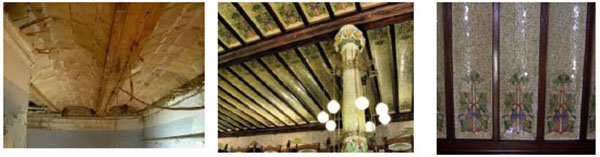
The recovery of this type of slab is based on traditional slabs forged with timbrel brick vaulting and a “trencadis” finish, which was popular in eastern Spain between the late 19th and early 20th centuries. The infill element consists of leftover ceramic pieces, mainly tiles, together with a formwork system (Fig. 4).
2. METHODOLOGY AND MATERIALS
2.1. Design Model: Geometric Definition and Typologies
The piece designed is composed of an arched lower layer made from recovered “trencadis” ceramics and a mortar filling flush to the upper face of the pre-existing beams. This design is for constructions with beams of variable width and a height of 14-16 cm (the normal cross-section dimensions for this type of slab). The gap between beams is that used in the most common inter-beam framework system of approximately 30 cm [21]. The design model is shown in Fig. (5).
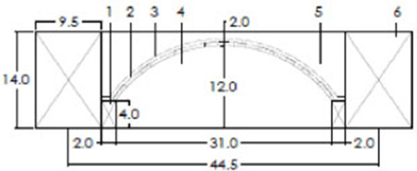
The configuration of the model is of a 12 cm cant and key thicknesses ranging between 2 and 4 cm depending on the height of the beams that are joined (14-16 cm). The cant of 12 cm was determined as a result of a previous test process with pieces with a 10 cm cant. The final model, with a cant of 12 cm, functions better structurally, acting as a discharging arch.
Table 1 shows the different key, theoretical and real thicknesses of each piece produced.
| Series | Piece | Piece height (cm) | Theoretical thicknesses key (cm) |
Real thicknesses key, mean value(cm) |
|---|---|---|---|---|
| A | 1 | 14.0 | 2 | 1.98 |
| B | 1 | 14.0 | 2 | 2.01 |
| 2 | 14.0 | 2 | 2.00 | |
| C | 1 | 15.0 | 3 | 1.89 |
| 2 | 15.0 | 3 | 3.12 | |
| 3 | 15.0 | 3 | 3.10 | |
| D | 1 | 15.0 | 3 | 2.25 |
| 2 | 15.0 | 3 | 2.33 | |
| 3 | 15.0 | 3 | 2.21 | |
| E | 1 | 16.0 | 4 | 4.35 |
| 2 | 16.0 | 4 | 4.73 | |
| 3 | 16.0 | 4 | 4.10 | |
| F | 1 | 15.0 | 3 | 2.67 |
| 2 | 15.0 | 3 | 3.47 | |
| 3 | 15.0 | 3 | 3.18 |
2.2. Materials
2.2.1. Ceramic Waste
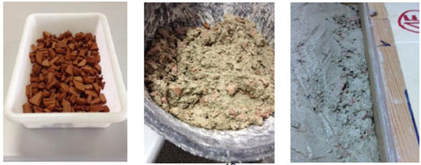
The small fragments of ceramic waste selected in the production of the pieces come mainly from demolished floors and fillers used in floor structures and slopes in the original roof coverings of this building typology. The floors consist of tiles measuring 14x28x1 cm, and the fillers are made of “alcatifa”, a waste product composed mainly of charcoal, bits of ceramic and mortar (Fig. 6).
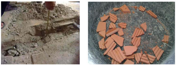
After preliminary grinding of the original pieces, fragments of less than 40 mm were selected by passing them through a sieve with a mesh width of 40 mm; the parts that remained in the sieve were reground and passed through the sieve again in order to use the maximum number of pieces. In addition, the F series of pieces of ceramic fragments were used not only to produce the first layer of the curved soffit, but also as an aggregate substitute for the sand in the mortar filler. In this case the fragments passing through a sieve with a 15 mm aperture were selected.
2.2.2. Cement
To give the piece a more pleasing aesthetic, a white cement binder was used with the designation BL II/A-L 42.5 R, in other words, cement with added limestone (L), with a strength after 28 days superior to 42.5 MPa and with a high initial resistance (R) [22].
2.2.3. Aggregates
For mortar manufacture, a commercial aggregate with 2 selections was used:
- Maximum aggregate size of 4 mm (MAS: 4 mm): A, B and C series.
- Maximum aggregate size of 8 mm (MAS: 8 mm): D, E and F series.
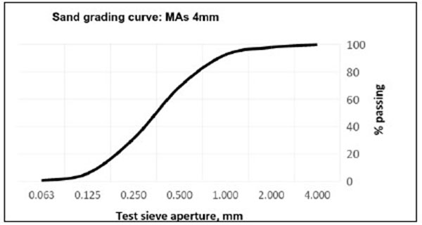
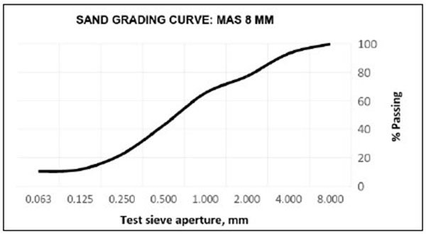
The test results for grading [23] are shown in Tables 2 and 3.
| MAS: 4mm. Total mass for the test(M1): 200 g. | |||
|---|---|---|---|
|
Test sieve aperture (mm) |
Mass of the material retained, Ri (g) |
Percentage retained, Ri/M1x100 (%) |
Percentage passing, 100-(Ri/M1x100) (%) |
| 4.00 | 0.67 | 0.33 | 99.66 |
| 2.00 | 3.85 | 1.92 | 98.07 |
| 1.00 | 10.76 | 5.38 | 94.62 |
| 0.50 | 46.90 | 23.45 | 76.55 |
| 0.25 | 75.73 | 37.86 | 62.13 |
| 0.125 | 50.81 | 25.40 | 74.59 |
| 0.063 | 10.16 | 5.08 | 94.92 |
| Material on the tray, P | 0.85 | ||
| Sum of the masses | 198.9 | SM+P=199.75 | |
| MAS: 8mm. Total mass for the test (M1): 1000 g. | |||
|---|---|---|---|
|
Test sieve aperture (mm) |
Mass of the material retained, Ri (g) | Percentage retained, Ri/M1x100 (%) |
Percentage passing, 100-(Ri/M1x100) (%) |
| 8,00 | 16.00 | 1.60 | 98.40 |
| 4.00 | 67.14 | 6.74 | 93.29 |
| 2.00 | 159.91 | 15.99 | 84.01 |
| 1.00 | 117.82 | 11.78 | 88.22 |
| 0.50 | 227.28 | 22.73 | 77.28 |
| 0.25 | 204.08 | 20.41 | 79.59 |
| 0.125 | 106.20 | 10.62 | 89.38 |
| 0.063 | 13.16 | 1.32 | 98.68 |
| Material on the tray, P | 1.67 | ||
| Sum of the masses | 911.59 | SM+P=913.26 | |
The grading curves are represented as follows (Fig. 7 and 8).
2.2.4. Mortar
Various dosages were applied to prepare the mortar filler we applied, at 1:6 (series A), 1:6 with an EPS granulate replacing a fraction of the aggregate, in a proportion of 2% on the weight of cement (series B), and 1:5 (series C, D, E and F).
The mechanical characterization of the mortar was obtained using prism samples measuring 40x40x160 mm3 according to UNE EN 1015-11:2000 / A1:2007 [24]. These samples were tested for bending and compression, and the results are shown in Table 4.
| Series | Mortar dosage |
Density (Kg/m3) Mean value (CoV, %) |
Bending strength (N/mm2) Mean value (CoV, %) |
Compression (N/mm2) Mean value (CoV, %) |
|---|---|---|---|---|
| Series A | 1:6 | 4621.23 (0.02) |
1.32 (11.82) |
3.44 (8.05) |
| Series B | 1:6 with EPS | 3988.18 (0.26) |
0.61 (7.69) |
1.24 (12.90) |
| Series C | 1:5 | 4474.06 (0.19) |
1.79 (6.95) |
5.092 (6.83) |
| Series D | 1:5 | 3995.04 (0.19) |
2.71 (3.65) |
11.80 (5.53) |
| Series E | 1:5 | 4382.27 (0.13) |
2.74 (7.43) |
10.36 (4.45) |
| Series F | 1:5 | 4129.32 (0.021) |
3.39 (7.09) |
10.78 (10.99) |
As is shown in Table 4, with the addition of EPS in the mortar dosage, the strength values decrease significantly for both bending and compression. Likewise, the results for the A and B series specimens show an increase in cement content, rising to a dosage of 1:5 (series C, D, E, F), which in turn gives better results for strength, both in bending and compression.
At these dosage levels, the water/cement ratio (w/c) in the mortar is high to facilitate workability and bonding with the reused ceramic pieces. Further research could test for a lower water/cement ratio by adding fluidizing additives, if it is deemed necessary to increase the resistance values.
2.2.5. Fibreglass
A fabric veil was used to increase the strength of the pieces for the A, B and C series. The fiberglass fabric is produced in the same way as for textile fibres, and is prepared with an anti-alkaline coating. In the D, E and F series, this reinforcement is eliminated in order to optimize the sustainability of the piece, comparing the mechanical strength of the pieces in each series. The characteristics of the fibreglass used are:
- Density: 300gr/m2
- Tensile strength: 2940 MPa
- Tensile modulus: 76 Gpa
The characteristics of the components of each series are shown in Table 5.
| Series | Piece number |
Real thicknesses key, mean value (cm) |
Mortar dosage |
MAS (mm) |
Fibreglass reinforcement | Recycled ceramic weight (Kg) |
Final weight of the piece (Kg) |
|---|---|---|---|---|---|---|---|
| A | 1 | 2.00 | 1:6 | 4 | YES | 1.15 | - |
| B | 1 | 2.00 | 1:6 with EPS |
4 | YES | 1.15 | - |
| 2 | 2.00 | 1:6 with EPS |
4 | YES | 1.15 | - | |
| C | 1 | 2.58 | 1:5 | 4 | YES | 1.15 | - |
| 2 | 3.12 | 1:5 | 4 | YES | 1.15 | - | |
| 3 | 3.10 | 1:5 | 4 | YES | 1.15 | - | |
| D | 1 | 2.25 | 1:5 | 8 | NO | 1.15 | 17.60 |
| 2 | 2.33 | 1:5 | 8 | NO | 1.15 | 17.90 | |
| 3 | 2.21 | 1:5 | 8 | NO | 1.15 | 17.13 | |
| E | 1 | 4.35 | 1:5 | 8 | NO | 1.15 | - |
| 2 | 4.73 | 1:5 | 8 | NO | 1.15 | 24.60 | |
| 3 | 4.10 | 1:5 | 8 | NO | 1.15 | 23.20 | |
| F | 1 | 2.67 | 1:5 | 8* | NO | 2.30 | 18.60 |
| 2 | 3.47 | 1:5 | 8* | NO | 2.30 | 20.00 | |
| 3 | 3.18 | 1:5 | 8* | NO | 2.30 | 19.20 |
3. EXECUTION PROCESS
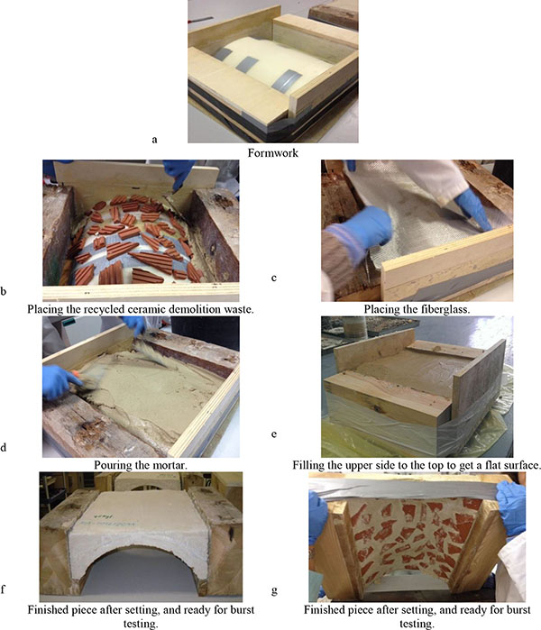
The mold was made from extruded polystyrene as the base material, and was used as the formwork. As indicated in Fig. (5), the mold had a width of 31 cm and height of 12 cm, corresponding to the cant height (Fig. 9). First, the mold was vectorized in a design program and then shaped by a milling machine set up in an ETSA (FabLab) mock-up laboratory.

Once the mold was completed, it was coated with a PVC sheet to avoid contact with the mortar and to facilitate the subsequent demolding of the piece. To reproduce the work conditions, two pieces of wood measuring 9x14-15x31 cm were placed on either side of the mold to simulate the floor beams and simultaneously act as a formwork (Fig. 10a). With the pieces of wood in place around the mold, the ceramic pieces to be reused were then arranged. A first layer of about 2 cm of mortar was poured into the mold (Fig. 10b), and the fibreglass veil placed over the A, B and C series (Fig. 10c). Finally, the mould was filled to the height of the wooden beams. It is very important to fill the upper surface of the slab to the top and produce a flat surface in order to achieve a uniform support for the burst test (Figs. 10d and 10e). At the end of the production process, the mortar required a 28-day setting period after which burst tests could be carried out (Figs. 10f and 10g).
As noted in chapter 3, the percentage of recycled ceramic was increased in pieces from the F series compared to the other series. In fact double the content was used in this series, with the curved soffit used not only as a finishing material but also as an aggregate, replacing some of the sand component of the mortar filling. Ceramic fragments passed through a sieve with a 15 mm aperture were used in this filling (Fig. 11).
4. MECHANICAL TESTS
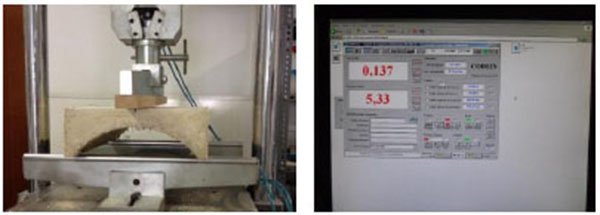
There is no standard for testing this item since it is a new element composed of ceramic material and mortar with no specific application norms. So, the procedure used was that described in the UNE 67-042-88 [25] standard for testing large baked clay pieces, as there was similarity in the shape of the elements.
This test was made using a press capable of applying the load at a speed of 5 kgf/s, with a two-prop patella plate, one fixed and the other articulated. The load was applied at the midpoint of a parallel-piped piece of wood 5 cm wide and 3 cm high, and of a length equal to or greater than the width of the piece, as shown in Fig. (12).
According to the standard [25], the test result was ranked as positive when the specimen was able to withstand a load of 125 kgf without breaking.
5. RESULTS AND DISCUSSION
The test results are shown in Table 6.
| Series | Piece number |
Real thicknesses key, mean value (cm) |
Mortar dosage |
MAS (mm) |
Fibreglass reinforcement |
Ultimate load (Kgf) |
Ultimate load, mean value (Kgf) |
|---|---|---|---|---|---|---|---|
| A | 1 | 2.00 | 1:6 | 4 | YES | 72.0 | 72.0 No satisfied |
| B | 1 | 2.00 | 1:6 with EPS | 4 | YES | 28.6 | 27.1 No satisfied |
| 2 | 2.00 | 1:6 with EPS | 4 | YES | 25.5 | ||
| C | 1 | 2.58 | 1:5 | 4 | YES | 96.0 | 114.3 No satisfied |
| 2 | 3.12 | 1:5 | 4 | YES | 110.0 | ||
| 3 | 3.10 | 1:5 | 4 | YES | 137.0 | ||
| D | 1 | 2.25 | 1:5 | 8 | NO | 137.0 | 136.7 satisfied |
| 2 | 2.33 | 1:5 | 8 | NO | 142.0 | ||
| 3 | 2.21 | 1:5 | 8 | NO | 131.0 | ||
| E | 1 | 4.35 | 1:5 | 8 | NO | 427.0 | 388.3 satisfied |
| 2 | 4.73 | 1:5 | 8 | NO | 389.0 | ||
| 3 | 4.10 | 1:5 | 8 | NO | 349.0 | ||
| F | 1 | 2.67 | 1:5 | 8* | NO | 234.0 | 339.0 satisfied |
| 2 | 3.47 | 1:5 | 8* | NO | 457.0 | ||
| 3 | 3.18 | 1:5 | 8* | NO | 326.0 |
The results indicate that:
- Pieces made with a mortar dosage of 1:6 did not reach the minimum strength value in line with UNE 67-042-88 [25]. Switching to a dosage of 1:5 saw a significant increase in the load-bearing capacity of the element, with an average value in the C series of 114.3 kgf, in some cases exceeding the established minimum strength of 125 kgf. Moreover, lower values were recorded in mortars with added EPS.
- The strength values of the pieces increased when the maximum aggregate size of the mortar was raised from 4 to 8 mm. Average values reached 114.3 kgf for a 4 mm MAS and 136.7 kgf for an 8 mm MAS in the C and D series, respectively. Also, F series pieces in which fragments of recycled ceramic were used in the mortar with a 15 mm MAS recorded an average bending strength of 339 kgf.
- As the thickness of the key element increases, it becomes stronger. The pieces with a similar mortar and sand dosage (1:5) and the same MAS (8 mm) recorded average strength values of 136.7 for key thicknesses of 2 to 2.5 cm, and 388.3 kgf for key thicknesses of 4 to 5 cm in the D and E series, respectively. In the case of the E series with thicknesses of between 4 and 5 cm, the strength values obtained amply exceeded the values for standard thicknesses, making it feasible to reduce key parts and therefore optimize both the final weight of the finished item as well as the cost of the slabs.
- The addition of a fibreglass veil did not yield a significant improvement in the piece’s flexural strength so it can be discarded, thereby reducing the final cost of the piece and increasing its sustainable value.
- The weight of the finished element enables us to estimate the weight of a 1 m2 slab constructed using the system proposed. So, for beams with a 14 cm edge, the slab weight estimate is 0.506 KN / m2. The addition of a 6 cm compression layer gives the following final loading per square meter:
- Conventional concrete: (1.44KN/ m2): 1.95 KN/m2
- Lightweight aggregate concrete: (0.84 KN/m2): 1.34 KN/m2
The low weight for 1 m2 of this type of slab compared to other slab building systems [26] means that the strength capacity of the traditional load-bearing walls of these building types is not diminished [27].
CONCLUSION
A new infill piece is developed in this paper, and the conclusions we have drawn from its development are the following:
- The application of this new piece enables the reuse of existing wooden beams in the rehabilitation work; these retain adequate bearing capacity regardless of their aesthetic deterioration.
- The pieces we have developed enable the reuse of ceramic waste generated in the rehabilitation work and in the building production industries. According to data from the manufacture of each series, it is possible to reuse the following quantities of ceramic waste per m2:
- § Series A-E: 2.875 g/m2
- § Serie F: 5.750 g/m2
This means we can recycle waste material and reduce the presence of less sustainable materials which this waste material can replace.
- These pieces enable us to produce slabs that are lighter than more traditional slabs. The weight of the slab with recovered wooden beams and joists with recycled ceramic mortar and a total depth of 0.20 m (a 6 cm compression layer of lightweight aggregate) is 1.34 kN/m2, which is favorable when compared to other solutions for rehabilitating existing slabs.
- The model proposed is a good solution for the floors of buildings of the type studied, and is consistent with the strength capacity of the original structural walls of the building [27].
The model proposed is still under study and the aim is to use a bigger quantity of demolition waste and develop a piece of plastic formwork that can be adapted to the different spaces that require such pieces on site.
CONFLICT OF INTEREST
The authors confirm that this article content has no conflict of interest.
ACKNOWLEDGEMENTS
This research has been supported by the Ministry of Economy and Competitiveness of Spain (reference number BIA2013-43061- R).Also, the author Mª Jesús Morales Conde acknowledges the financial support of the V Research Plan of the University of Sevilla.

