All published articles of this journal are available on ScienceDirect.
The Effectiveness of Eugenia Oleina in Protecting Tropical Residual Slope from Excessive Shear Failure
Abstract
Introduction
Slope stability and soil erosion are major concerns in geotechnical engineering and land management. This research investigates the relationship between soil type and root systems in stabilizing slopes.
Methods
The main aim is to measure the effectiveness of Eugenia Oleina as a bioengineering technique for slope protection. Laboratory tests were conducted to measure soil shear strength, root properties, and the factor of safety (FOS) of tropical slopes before and after plant root implementation.
Results
Results revealed significant differences in cohesion and angle of friction values between unrooted and rooted soil. Apart from that, it was observed that as the root diameter increased, the tensile strength decreased when the applied force increased. The FOS of unrooted soil was higher than rooted soil, indicating greater stability without any vegetation. Furthermore, this study also evaluated the use of bio-anchorage to prevent soil erosion, considering factors such as soil composition, vegetation, and external loads. Finite element analysis was carried out using Plaxis 3D simulations to assess the effectiveness of Eugenia Oleina in controlling slope erosion.
Conclusion
This study contributes valuable insights in choosing suitable plant species for erosion control in tropical soil and guides soil bioengineering practices for slope stability in various soil conditions.
1. INTRODUCTION
Landslides are one of the most hazardous and pervasive threats worldwide, claiming thousands of lives and causing billions of dollars in damage. The increasing development on mountainous terrains has exacerbated the danger, posing a serious threat to both physical infrastructure and inhabitants [1]. Recent studies reveal a growing trend in the location, quantity, activity, frequency, and social and economic impacts of landslides, exposing more people to these hazards [2].
In Malaysia, rapid urbanization in hilly locations has stressed the terrain and led to slope failures due to reduced protective forces and safety factors [3]. Unlike rock slopes, soil slope collapses involve substantial amounts of failed material [4]. Based on Lias et al. [5], rainfall is one of the elements that contribute to slope failure. Turf and topsoil fragments from the slope surface are eroded by rainfall runoff to the slope. Rainfall is the main cause of landslides, so it is important to assess the relative significance of heavy rainfall and antecedent rainfall as well as how these factors may change the pattern of the rainfall threshold [6]. According to Gidon and Sahoo [7], the rise in pore water pressure caused by heavy rain on unsaturated soil causes landslides to occur. High rainfall and ambient temperature in the tropics result in severe chemical weathering and the development of loose soil profiles which promotes soil erosion [8].
Geotechnical engineering faces the challenging issue of slope failure caused by soil erosion during rain, and a significant problem for slope protection strategies involving vegetation [9]. As a result, researchers found a method to fix the problem by combining engineering and geo-environmental tools known as bio-geo-engineered techniques.
One of the alternative technologies to prevent shallow landslides, particularly during the rainy season, is the use of vegetation in bioengineering. Referred to as 'bioengineering,' this approach utilizes plants to stabilize slopes, where the hydromechanical aspects of the vegetative contribution play a crucial role [10]. Various factors such as slope steepness, root characteristics, soil aggregate, vegetation type, and spacing can either increase or decrease slope stability through hydromechanical vegetation effects [11]. Based on Masi et al. [12], the effect of vegetation on mechanical and hydrological soil behavior is an important issue to consider when modeling shallow landslides.
Roots significantly influence slope stability, offering reinforcement through increased soil cohesion and mechanical stabilization through tensile strength, frictional properties, bending stiffness, root distribution and orientation. This paper aims to provide a comprehensive review of the interaction between soil matrix and root pattern, elucidating its role in increasing shear strength.
1.1. Soil Bioengineering Techniques
Steep slopes can be replanted using soil bioengineering techniques, and seepage zones can be treated, and surface erosion can be controlled [13]. Introducing and growing functional living communities that are capable of effectively ensuring the desired soil and slope protection and consolidation targets, soil bioengineering systems use plants and parts of plants as living building materials. These systems may also be supported by a wide range of materials and structures [14].
When utilizing plants as construction materials, roots imbue engineering structures with multifunctionality and meet the escalating societal demand for environmentally friendly approaches to design structures [15]. According to Rahman [16], “vegetation” encompasses the ground cover provided by plant communities and refers to tree planting as crucial in maintaining soil mass through hydrological and mechanical mechanisms. From a mechanical perspective, vegetation strengthens the soil by transmitting shear stress to the root fibers through mobilized tensile strength in the roots [17]. Plant roots form a dense network that binds unconsolidated materials, preventing sliding and enhancing slope stability. They contribute tensile strength, increase matric suction, and dissipate excess water pressure, thereby promoting soil stability [18].
Based on Fata et al. [11], the impacts of hydromechanical vegetation could make a slope more stable. Plants can influence slope hydrology and thus stability in a variety of ways, including transpiration-induced suction, rainfall interception, and root change of soil water retention qualities [19]. The foundation of bioengineering employing natural vegetation is the use of live plants found in nature and adapting engineering techniques to improve the stability of eroding slopes, stream banks, and trail systems [20]. A landslide due to lateral failure or basal failure plane can both be reinforced by roots. Particularly in weak soils in highland areas, roots can penetrate bedrock cracks and fractures to attain a strong and deep anchoring for the plant [12].
1.2. Root System Characteristics
It is well known that plant roots significantly improve slope stability and tree stability. The use of vegetation to prevent soil erosion and maintain slope stability has been used all around the world. In the face of environmental issues including landslides, water loss, and soil erosion, the anchoring and strengthening of roots and soil are crucial [21]. The root system is responsible for anchoring vegetation to the earth, and other important tasks. A reinforced soil matrix is created by the ground, roots, and linkages. This matrix can transfer pressures from the soil to the roots, enhancing the total strength [12]. Root biomass tends to increase soil-root interactions and surface roughness by adding organic substances into the soil [22].
Various studies have explored the root mechanical characteristics, which vary based on species and regional factors like water and nutrient availability. Generally, roots grow close to the ground surface to access water, oxygen, and nutrients in areas with lower soil bulk density [23]. According to Carrete et al. [24], plant root growth can be altered by introducing obstacles in the path of growth. Studies have shown that roots can strengthen the ability of soil to resist landslides, water erosion, and boost streambank stability. In streambank soil, roots increase the ground resistance to compression [25].
In identifying the hydraulic activities of unsaturated soils, permeability is a fundamental soil characteristic that relates to both the qualities of water and soil [26]. It should be emphasized that, regardless of cohesive interactions, particles in sediments with low permeability may stick together when wet or saturated due to negative pore pressure [27].
1.3. Influence of Root Strength and Slope Stabilization
According to Mahannopkul and Jotisankasa [28], the effectiveness of bio-slope stabilization operations is significantly influenced by root tensile strength. The root moisture content and its suction can change seasonally in practice and might not be equivalent to soil suction because of evapotranspiration and climatic conditions. Most people agree that one of the most important factors for slope stability is root reinforcement [12]. Plants are active in holding and protecting soil particles on the surface as well as at deeper levels where they lower pore pressure and increase soil shear strength [29]. The earthen slopes are strengthened and made more stable by the vegetation's roots [30].
According to Wang et al. [31], the strength of the root composite increases with root design complexity and rainwater infiltration speed. It appears that the plant roots play a good influence on the strength of the root composite while having a negative effect on the infiltration of rainwater. The slope's stability is improved by vegetation roots lowering the moisture content of the soil's top layer [32]. The roots changed the soil's cohesiveness and suggested a vertical root system model based on the Mohr-Coulomb strength criterion, which has since been gradually improved and adjusted [33].
According to Yu et al. [34], plants' intertwined roots tend to compact the soil into a solid mass and increase bank strength by adding more apparent cohesiveness. When there are enough roots crossing the possible fissures defining the border of a surface landslide, slope stability may become more stable [35]. The strengthening of soil by plant roots, which results in an increase in soil shear strength, is one of the primary mechanical impacts [36]. The physical characteristics and spatial distribution of a plant's root system have a considerable impact on the soil's evident root-reinforcing effect [37].
2. METHODS
The study area for this research was carried out at the Universiti Malaysia Pahang (UMP), Gambang Campus, 3°43'4.19” N and 103°07'9.60” E. It covers an area of 126 acres and can accommodate up to 5,000 students. The three different slopes; slopes A, B, and C, from which the soil samples were taken, are located on a hillside close to the Faculty of Civil Engineering Technology (FTKA) laboratory. The slope area at Slope A has no trees planted. The slope regions at Slopes B and C are reserved as locations with trees. Slope B has a large tree roots, and Slope C has a little plant roots, to be more precise. Slope A spot served as a control location and was initially covered in green grass. In this research, the impact of grassroots on shear failure is neglected assuming very little or no severe issue. Grass protects the soil surface from any erosion from taking place hence no shear failure is expected from this research. These locations were chosen because a live pole had seriously eroded part of the slope's surface. The three slope segments were chosen so that it would be possible to comprehend how the tree roots are bound together and how this affects the overall stability. The various laboratory assessments, including sieve analysis, fine analysis, Atterberg limit, particle density, and specific gravity, were utilized to determine the different soil types for each location. A reservation was made for a plant, followed by its purchase, and subsequently, a root sample was gathered for the purpose of this study.
A shovel was used to gather the soil from each location into a bucket with a lid. To preserve the original moisture content of the sample, the disturbed sample was then placed in a plastic container with a lid. Soil samples on the slope for soil property analysis were collected from the same slope where the trees were planted for research. Three soil samples were collected from each of the slope A, B and C. Following that, a dry sample of the soil from sites A, B, and C was obtained by transferring it to a container and oven dried, as illustrated in Fig. (1). The soil sample was then kept for experimental investigation purposes in the Soil Mechanics and Geotechnical Laboratory, UMP. The slopes were chosen as the case study because they experience severe soil erosion, which, if its root cause is not discovered, could result in shallow slope failure.
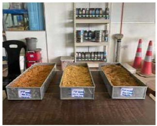
Dry samples of soil.
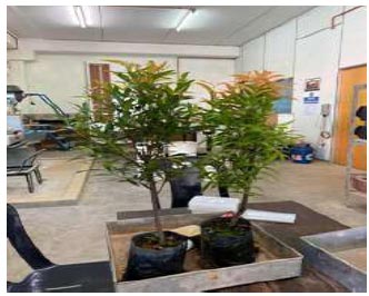
Eugenia oleina plants.
As for the roots, several Eugenia Oleina plants were purchased from a nearby nursery and placed in the laboratory as shown in Fig. (2). Then, the plants were segregated and the roots cleaned as shown in Fig. (3). Several measurements were recorded from the roots, including its length, diameter, and the number of fibrous roots using a Vernier caliper. Fig. (4) shows the roots were cleaned and preserved in a plastic container after being washed.
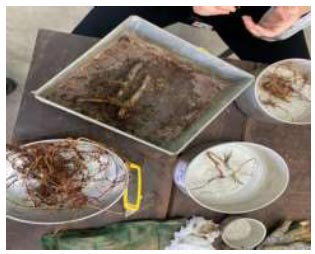
Cleaned roots of eugenia oleina.
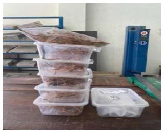
Roots preserved in containers.
2.1. Laboratory Test
Table 1 contains an overview of the laboratory tests that were performed. The American Society for Testing and Material (ASTM), British Standard (BS) and the American Association of State Highway and Transportation Officials (AASHTO) guidelines were followed during the execution of all tests.
2.2. Factor of Safety
According to Tosi [39], slope stability is analyzed using the infinite slope method. The Factor of Safety (FOS) for each sample was obtained using an equation that adopted the infinite slope method in the following form. The effect of vegetation on slope stability can be defined by the following relationship in Eq. (1) [38]:
 |
(1) |
Where;
FS = Factor of safety (FOS)
c' = soil cohesion (kPa)
∆s= root cohesion (kPa)
z = vertical depth of the failure plan (m)
β = Slope angle (°)
ϕ' = Soil friction angle (°)
γ' = γsat-γw “submerged” bulk unit weight
γsat = saturated bulk unit weight (kN/m3)
Wv = overload due to vegetation (kPa)
Table 2 presents the soil properties. In the case of bare/unrooted soil, the properties of root cohesion (∆s in kPa) and overload due to vegetation (Wv in kPa) are not taken into consideration. In this correlation, the tensile stress obtained from the field pull-out test was utilized as Wv. The specific results from the pull-out test were based on previous studies of [38] article.
| Properties | Code of Practices |
|---|---|
| Sieve Analysis | ASTM D422 |
| Fine Analysis | ASTM D422 |
| Atterberg Limit | BS 1377: Part 2: 1990 |
| Specific Gravity | ASTM D854 |
| Direct Shear Test | BS 1377 / ASTM D467 |
| Tensile Test | ASTM E8: ASTM D638 |
2.3. Software
This research is conducted by using a finite element method in software namely Plaxis 3D. A calculating kernel for 3D finite element calculations was created, resulting in the 2001 release of the 3D Tunnel software. Plaxis 3D is a comprehensive three-dimensional finite element software with an intuitive interface and full 3D modeling capabilities. The parameters from this research were subsequently utilized in Plaxis 3D for slope stability analysis, employing the Strength Reduction Method. This analysis allows for evaluating the safety of designs for both artificial and natural slopes, ensuring they meet equilibrium conditions.
2.4. Mesh Generation, Boundary Conditions and Material Modelling
Soil material properties are characterized, and data are assigned to clusters in geometry models. A finite element mesh is created by adjusting coarseness, and ten-noded tetrahedral elements are used to mesh three-dimensional slopes. The mesh was used in reference to previous research which is similar to this research scope. This is maintained in order to compare results and reduce biases in the findings.
| Slope | ||||||||||||
|---|---|---|---|---|---|---|---|---|---|---|---|---|
| Parameters | A | B | C | |||||||||
| Rooted | Unrooted | Rooted | Unrooted | Rooted | Unrooted | |||||||
| Number of Roots | 3 | 5 | 7 | 0 | 3 | 5 | 7 | 0 | 3 | 5 | 7 | 0 |
| Slope angle, β° | 27.6 | 27.37 | 26.69 | |||||||||
| Load of tree, kN | 0 | 266.701 | 3490.4 | |||||||||
| γunsat, kN/m3 | 13.56 | 13.49 | 13.68 | |||||||||
| γsat, kN/m3 | 22.96 | 23.64 | 22.76 | |||||||||
| Horizontal permbeability (m/day) | 1.0 | |||||||||||
| Horizontal permbeability (m/day) | 1.0 | |||||||||||
| Angle of friction, Ø′ | 20.25 | 18.06 | 18.58 | 17.03 | 28.06 | 27.3 | 20.03 | 18.14 | 29.54 | 22.12 | 21.39 | 17.16 |
| Cohesion, c’ kN/m2 | 21.25 | 10.92 | 17.07 | 33.44 | 19.77 | 19.78 | 20.37 | 35.07 | 28.7 | 19.72 | 26.22 | 31.77 |
| Dilatancy angle | 1.0 | |||||||||||
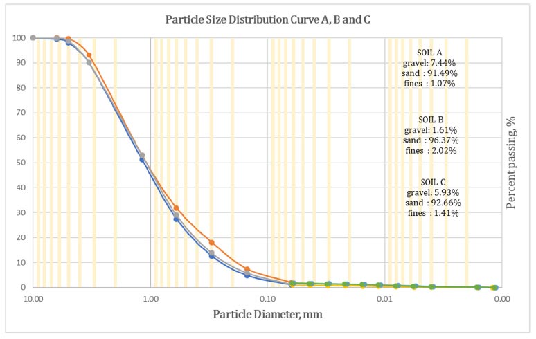
Graph of sieve analysis for each of the three slopes.
2.5. Initial Condition
After producing the mesh, initial conditions were established by setting water unit weight, water level, boundary conditions for closed consolidation, phreatic level water pressure, and initial stress. Initial stresses are calculated using the K_0 procedure and set the pore pressure calculation type to Phreatic. The Global water level was determined based on Borehole Waterlevel_1.
2.6. Consolidation
The consolidation procedure involves three loading types: “Staged construction” for initial construction under undrained conditions, “Minimum excess pore pressure” until excess pore pressures reach a predefined minimum value, and “Degree of consolidation” until a specified degree of consolidation is achieved. The default loading type is “Staged construction,” while phase 2 requires no changes to geometry and consolidation analysis until the final time. Phase 4 involves a consolidation analysis to attain a minimum excess pore pressure. The drained conditions analysis includes four phases, including activated drains and consolidation phases with 1-day intervals. The final phase aims for a minimum excess pore pressure of 1.0 kN/m2.
2.7. Simple Slope Application
To have a simple checking and comparison of slope stability in Plaxis 3D, the Simple Slope application was used. Simple Slope application was installed from the Play Store on mobile phones.
| Slope Properties | A | B | C |
|---|---|---|---|
| Liquid Limit (LL), % | 51.77 | 49.16 | 42.45 |
| Plastic Limit (PI), % | 11.29 | 14.17 | 12.40 |
| Uniformity Coefficient (Cu) | 5.59 | 7.38 | 5.95 |
| Coefficient of Gradation (Cc) | 1.22 | 1.23 | 1.25 |
| Group Classification | A-2-7 | A-2-7 | A-2-7 |
| Type of Soil | Sandy Silt | Sandy Silt | Sandy Silt |
3. RESULTS AND DISCUSSION
3.1. Soil Type and Engineering Properties
A comprehensive classification of soil relies on the examination of various crucial soil properties, encompassing sieve analysis, liquid limit (LL), plastic index (PI), uniformity coefficient (Cu), and coefficient of gradation (Cc). These properties serve as key indicators when assessing the behavior and characteristics of soil. In the context of this research, a meticulous comparison will be conducted between the soil's original state and its altered properties. This approach ensures the acquisition of accurate and reliable results for the study. By scrutinizing these observed changes, a deeper comprehension of the soil's behavior can be attained, unveiling valuable insights into its composition, structure, and potential applications. Fig. (5) depicts a sieve analysis graph for each of the three slopes in one graph. Table 3 contained data that provided a thorough understanding of soil composition, structure, and potential applications.
Using ASTM, BS, and AASHTO standards, the soil was systematically categorized based on meticulous data analysis and comprehensive laboratory tests conducted. The rigorous investigation undertaken ultimately culminated in the compelling conclusion that the soils present at all examined sites exhibit remarkably similar attributes and characteristics. Notably, the recorded values of plasticity remain well below the 20% threshold, indicating a commendably moderate degree of plasticity within the soil composition. Consequently, the soil was appropriately classified as sandy silt (SM), earning a commendable group classification of A-2-7. The research was limited to soil moisture content only. Soil moisture test was conducted using a standard method in accordance with BS. No root moisture was included as a factor in this research.
3.2. Root Morphology
According to Duraisamy et al. [38], The morphology and growth patterns of plant species vary, primarily determined by their resource acquisition capabilities and competitive abilities. Shrubs and trees typically exhibit the development of branches and longer roots, as opposed to grass species. In terms of root structure, thicker roots typically exhibit higher ultimate tensile strain values compared to thinner roots [39]. In general, this type of root tends to grow horizontally, known as the H-type, and serves as reinforcement for the soil.
3.3. Direct Shear Box Test
Referring to Fig. (6), it is evident that root-reinforced soil exhibits a significantly higher shear strength in comparison to bare soil. Among the three slope A, B, and C conditions examined, the seven-rooted soil demonstrates the greatest shear strength with 156.4 kPa, 159.2 kPa, and 197.4 kPa. The unrooted soil exhibits the lowest shear strength under the applied normal stress. This discrepancy can be attributed to the absence of roots in the unrooted soil sample, which fails to contribute to the enhancement of shear strength observed in the other conditions with 129.7 kPa, 149.3 kPa, and 149.7 kPa.
According to Nordin Abdullah et al. [3], the researchers also made an important observation regarding the impact of increased load on shear strength. It was found that as the load increased, the shear strength of the soil also increased. The findings obtained in this study are consistent with the observations made by Maffra et al. [40] to assess the impact of roots on the shear strength of both clay and sandy soils, the inclusion of roots in both sandy and clay soil resulted in a noticeable enhancement of shear strength in the tested specimens. Past research by Meng et al. [41] also found that under identical stress conditions, the shear strength of soil reinforced with roots is superior to that of plain soil.
Fig. (7) shows a linear decrease in cohesion (kPa) values for all three slopes, with lower cohesion in rooted soil compared to unrooted soil, and an increase in friction angle (˚). According to Emadi-Tafti et al. [42], the role of trees in improving soil conditions is significantly influenced by the level of soil cohesion. When soil cohesion is low, the beneficial effects of trees in enhancing soil stability diminish.
Based on the findings obtained from the shear test results, it can be concluded that the variation in shear strength between rooted soil and bare soil is not deemed significant. Building upon previous research, Maffra et al. [40], in relation to the impact on cohesion, it can be inferred that an elevation in this characteristic is anticipated when the roots intersect the failure surface. The presence of shrub roots has been found to considerably augment soil cohesion, with a stronger correlation between root content and the extent of cohesion enhancement [43]. According to Fahim Badhon [44], the rooted sample exhibits a higher angle of internal friction compared to the bare soil, indicating increased resistance to shear forces. However, the cohesion of the rooted sample is lower than that of the bare soil in both cases, implying a reduced binding strength between soil particles.
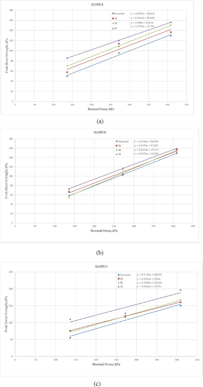
Comparison of shear strength over normal stress of (a) Slope A, (b) Slope B, and (c) Slope C.
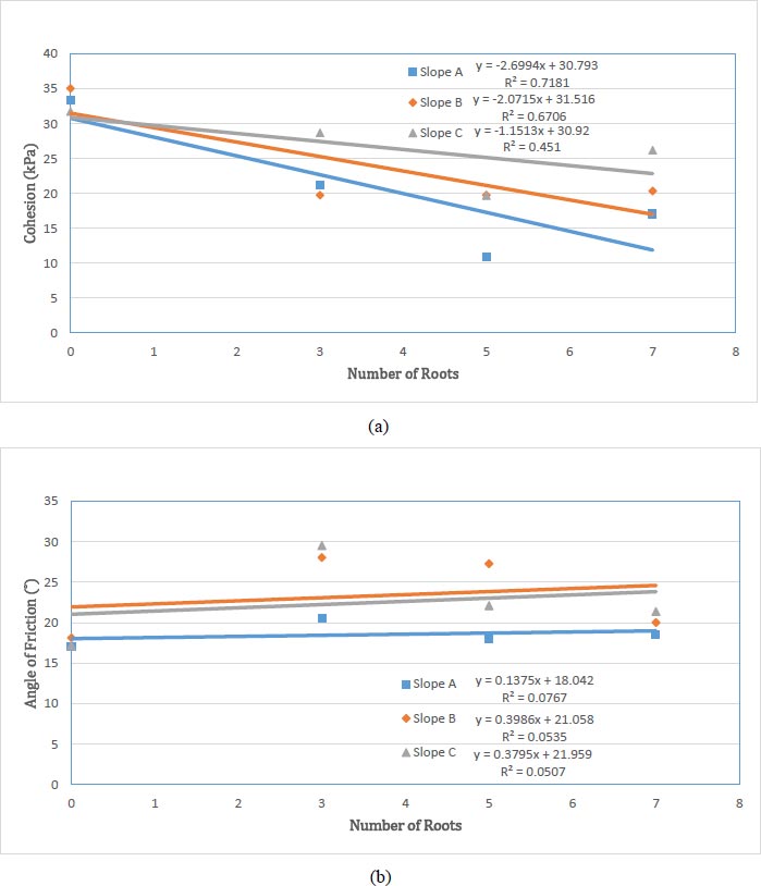
Comparison of number of roots with (a) Cohesion, kpa and (b) Angle of friction.
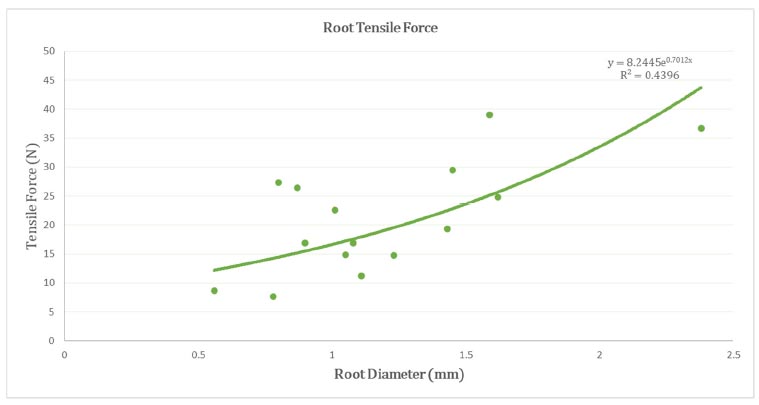
Correlation between tensile force and root diameter.
3.4. Root Tensile Strength Testing
Fig. (8) shows the relationship between tensile breaking force (TBF) and root diameter. The tensile force rose with increasing root diameter. This correlation can be effectively represented by an exponential regression curve in Eq. 2, adhering to the provided equation format. Where in this equation, TBF represents the tensile breaking force in Newton (N), D denotes the root diameter in millimeters (mm), and the constants a and b in the exponential relationship.
 |
(2) |
The roots of Eugenia Oleina were categorized into five groups based on their length over diameter ratio to assess the average tensile strength. As depicted in Fig. (9), there was a linear increase in the relationship between tensile strength and length over diameter ratio. According to G. Meijer et al. [45], the measured root tensile strength and stiffness showed an upward trend as the root diameters increased. However, it is important to note that the results exhibited significant variability or scatter for both parameters.
The formula utilized to determine the tensile strength, Tr, can be expressed through Eq. 3. In this equation, Fmax represents the maximum force (measured in N) attained during root rupture, while D signifies the diameter of the root in millimeters.
 |
(3) |
Furthermore, when examining Fig. (10), the results demonstrate a power law relationship between the root tensile strength and the diameter of roots. The graph illustrates that as the diameter of roots increases, the root tensile strength decreases. The values of the tensile strength range from 5 to 50 kPa, and this relationship can be described using Eq. 4. In this equation, Tr represents the root tensile strength in kilopascals (kPa), D denotes the root diameter in millimeters (mm), and the constants a and b are involved in the power law function relationship.
 |
(4) |
According to Duraisamy et al. [38], previous studies have revealed a consistent pattern where the root tensile strength decreases as the diameter of the roots increases. The tensile force demonstrates a positive correlation with an escalating root diameter, conforming to a second-order polynomial regression curve. Contrarily, the tensile strength exhibits a negative relationship with an increasing root diameter, adhering to a power law curve [39]. Previous research by Moresi et al. [46] stated that a set of 346 undamaged roots, each with a diameter smaller than 1 cm and a consistent length of 20 cm, underwent testing to measure their tensile strength. As a general trend, the tensile strength (Tr) of the roots tends to decrease as the root diameter (D) increases. An inversely proportional relationship between root tensile strength and root diameter has been observed in various plant species. In these species, as the root diameter increases, the tensile strength tends to decrease [47].
According to Ali Pourmalekshah et al. [48], the tensile force rose with increasing root diameter, following a power law relationship. The tensile stress result revealed that when the diameter of the tree root increased, an increase was seen. Based on prior existing research of Hj Ali & Ali [49], regarding the tensile strength experiments, the findings demonstrated a decline in tensile strength as the root diameter increased.
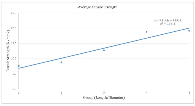
Tensile strength and length/diameter ratio relationship.
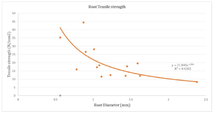
Tensile strength and length/diameter ratio relationship.
In Fig. (11), the research includes a comparative analysis of the tensile strengths of Eugenia Oleina in relation to other tropical plants. The results are presented in a single graph, allowing for a direct comparison. The previous tensile strength data for other tropical plants were obtained from the article by Duraisamy et al. [38]. Upon examining the graph, it can be concluded that Eugenia Oleina exhibits a lower tensile strength when compared to the other tropical plants, with Leucaena Leucocephala demonstrating the highest tensile strength among them.
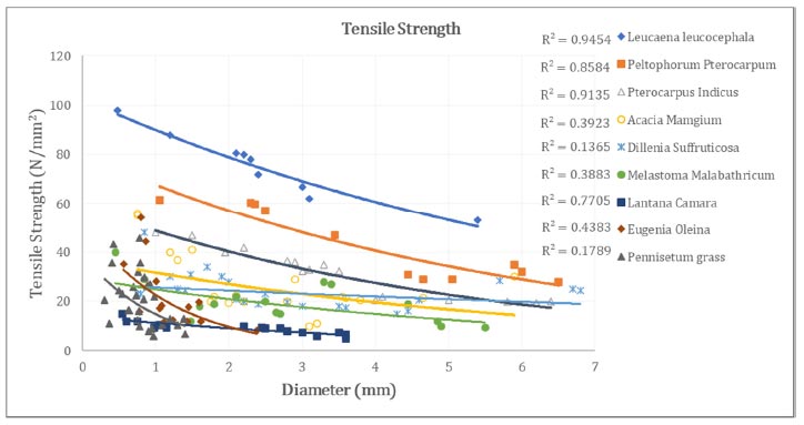
Tensile strength of eugenia oleina in contrast to other tropical plants.
3.5. Simulation of Slope Stability
In Plaxis 3D, the software calculates how the soil moves based on the applied loads and properties. It does this incrementally, at each step or load change. To show these movements, Plaxis 3D uses shading and arrows. Shading indicates the amount of movement, helping engineers see significant shifts. Arrows show both the direction and amount of movement at specific points in the soil or rock. Loadings from the trees are imposing greater movement as opposed to slopes with no trees. Especially when compared with Fig. (12) where Slope A with only grass vegetation has demonstrated very little soil movement or no movement at all. Similarly, all the other figure shows when there is an increase in the number of roots, there is a significant movement in soil regardless of the size of the trees.
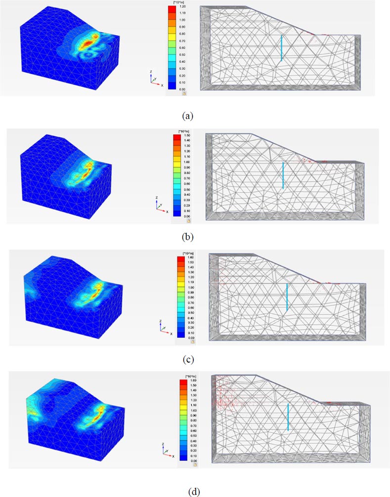
Incremental displacement of slope A (a) Unrooted; (b) 3 roots; (c) 5 roots; (d) 7 roots.
Based on Fig. (12), the unrooted slope A has the lowest incremental displacement which typically indicates minimal or negligible deformation or movement in that particular area. It also suggests that the corresponding portion of the slope experiences relatively small or insignificant displacements. It implies that the area is relatively stable and less prone to significant deformations or failures under the given loading conditions. In comparison to slope A with 3, 5, and 7 roots, incremental displacement of rooted slope increases, respectively. In slope A simulation, there was no tree loading applied since slope A has only grass vegetation.
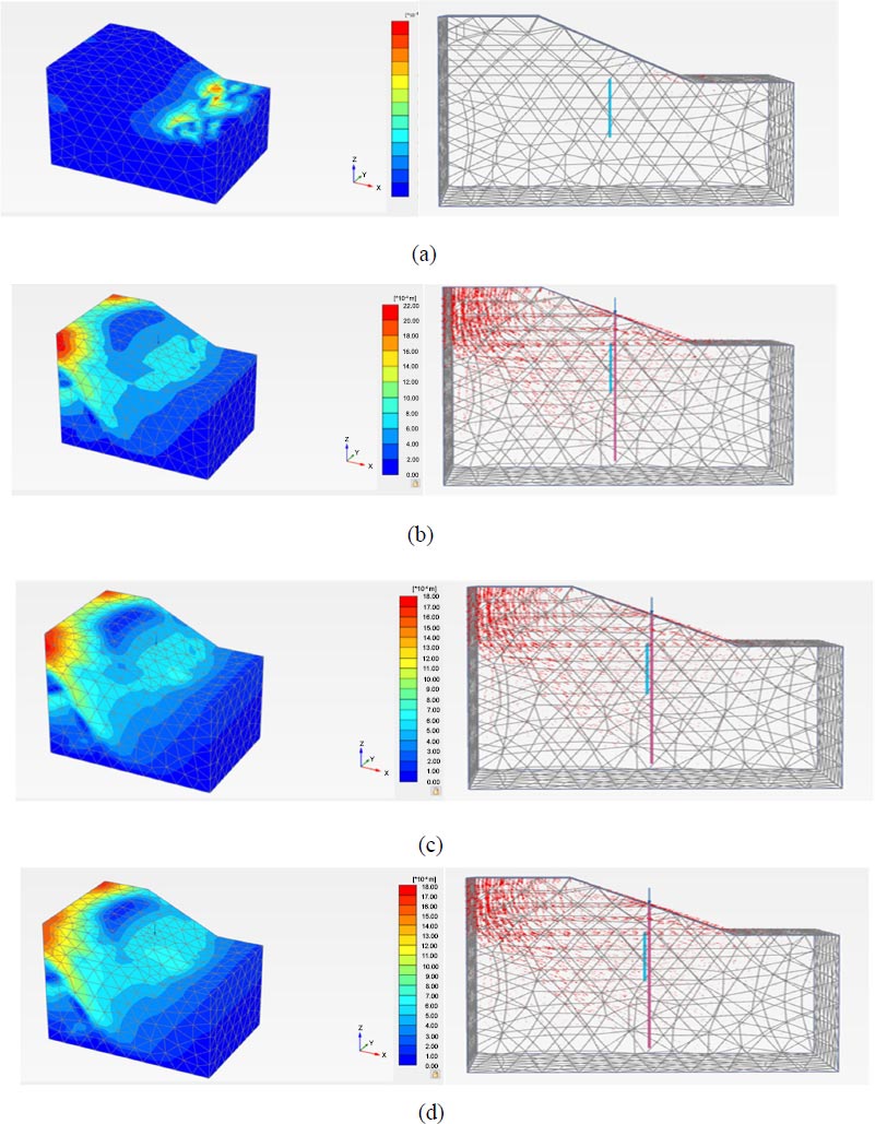
Incremental displacement of slope B (a) Unrooted; (b) 3 roots; (c) 5 roots; (d) 7 roots.
In slope B simulation based on Fig. (13), the load of the tree was applied which is 3490.4 kN. The age of the tree is around 13 years. Similar to slope A, the incremental displacement of slope B arises gradually from the bare slope to the slope with 7 roots. The growth and expansion of vegetation can exert additional stresses on the slope. The effects of the vegetation surcharge are leading to slope destabilization [50], resulting in an increase in normal stress and soil resistance to movement. Additionally, it increases the mass on slopes, creating a potential risk for landslides or soil erosion [51].
According to Fig. (14), in the simulation of slope C, a load of 266.702 kN was applied to a rooted slope, where the tree had a smaller diameter and height compared to slope B. Similarly, in slope B, the incremental displacement increased when transitioning from an unrooted slope to a rooted slope with seven roots. When comparing slopes A, B, and C, slope A shows the least incremental displacement, while slope B shows the highest. This study indicates that applying more loading to slopes with the same type of vegetation leads to increased soil movement.
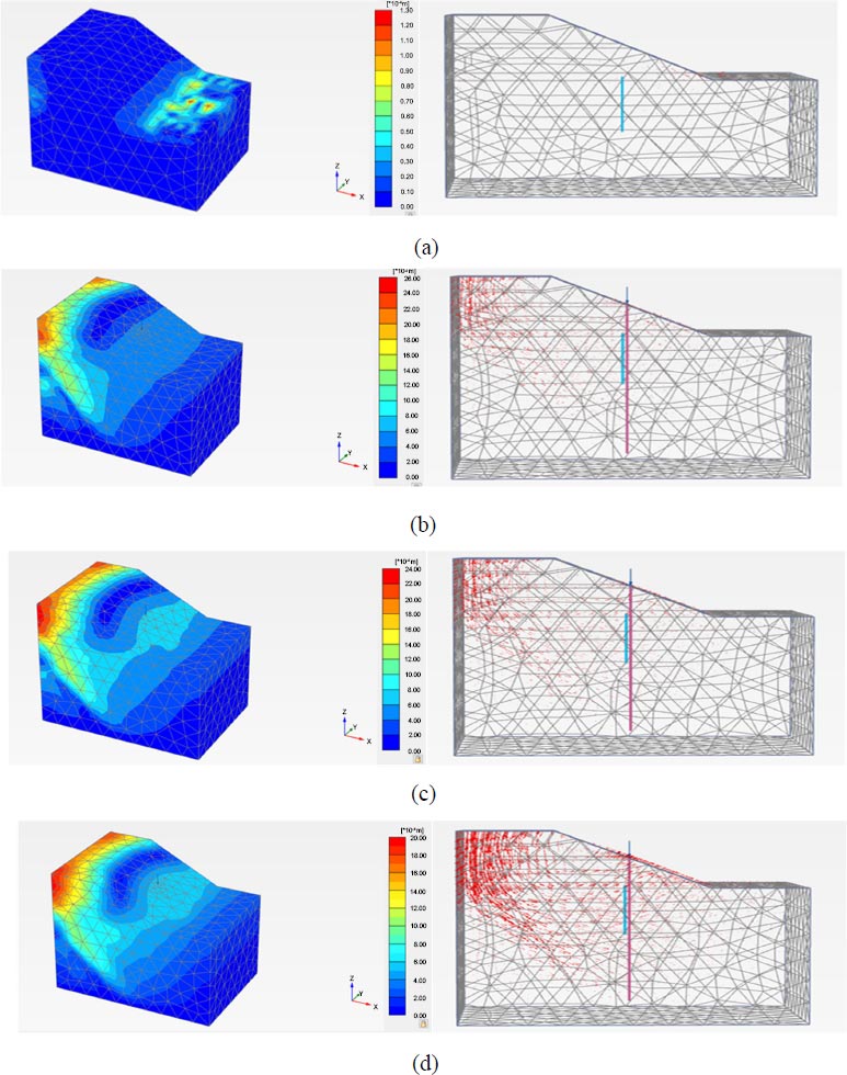
Incremental displacement of slope C (a) Unrooted; (b) 3 roots; (c) 5 roots; (d) 7 roots.
The factor of safety (FOS) between the unrooted and rooted slopes based on different approaches was calculated and presented in Fig. (15). All the parameters used in the calculation were obtained from the laboratory tests conducted, except for the field pull-out test data, which was sourced from previous research [38].
Based on the data presented in Fig. (15), there are variations in the FOS depending on the different approaches employed. FOS values vary depending on the approach used. In this research, a simple slope application using the Bishop method is used to validate the FOS obtained from Plaxis 3D software, which uses the Mohr-Coulomb method to assess the slope's acceptability. The lowest FOS value is found when a slope is planted with Eugenia Oleina species, indicating an unsafe condition compared to a slope without vegetation.
The Plaxis 3D software shows that rooted slopes A, B, and C with seven roots have FOS values of 6.05, 3.74, and 4.09, while unrooted slopes have higher FOS values of approximately 6.99, 5.75, and 6.11. The highest FOS value is found on slope A, which is the controlled slope. Although the differences in values are acceptable, the overall pattern of FOS for all three approaches remains consistent, showing a decrease in FOS values from unrooted slopes to rooted slopes with seven roots. According to Duraisamy et al. [38], the stability of a bare slope with a 25° gradient can be demonstrated by the fact that it remains highly stable even when up to 80% of the soil becomes saturated. Therefore, it is justified when unrooted slopes recorded the highest FOS compared to rooted slopes.
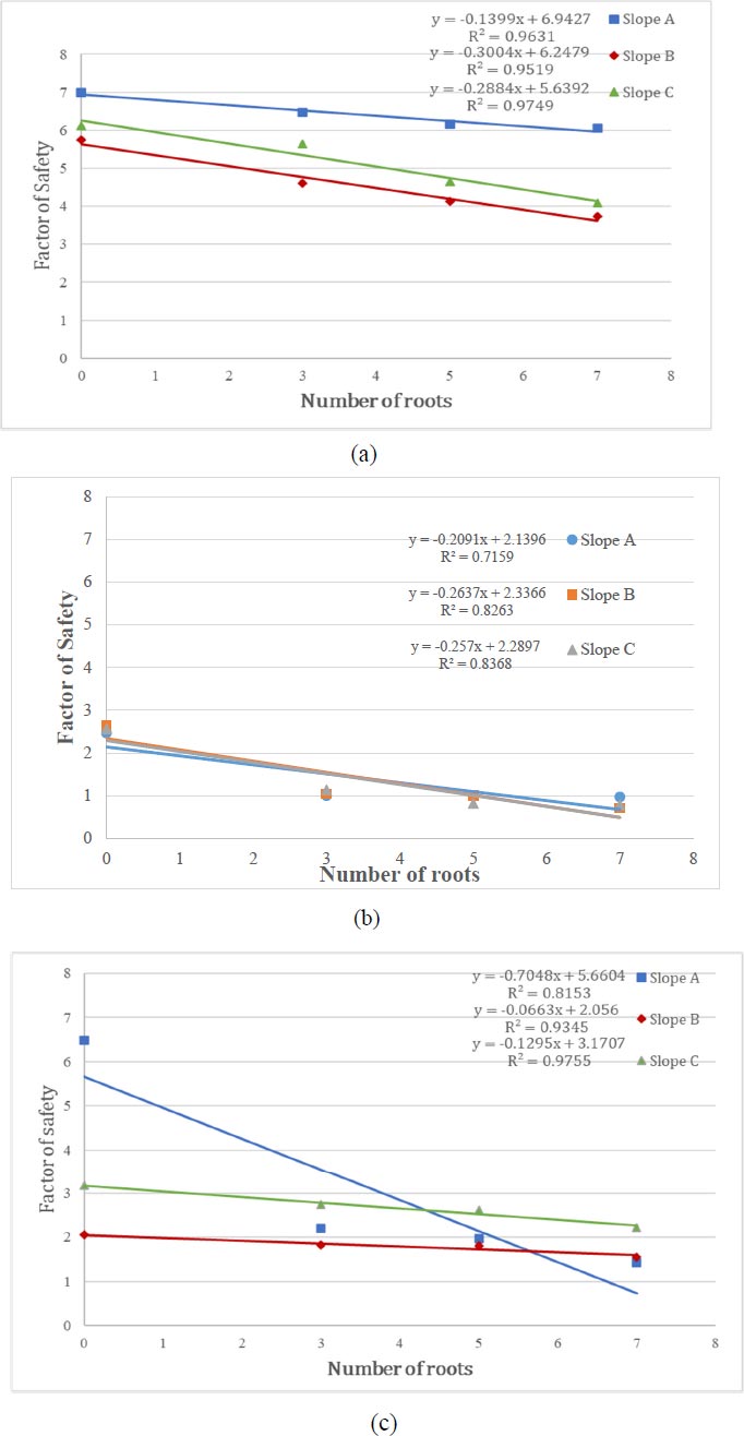
FOS from (a) Plaxis 3D (b) Simple slope mobile application (c) Manual calculation.
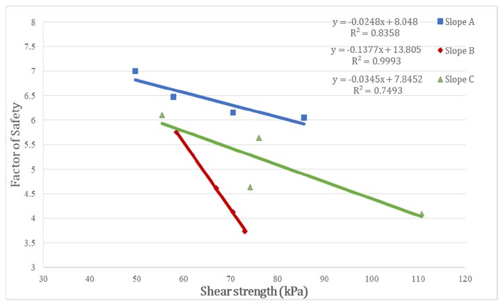
FOS from plaxis 3D against shear strength of soil at 136.2 (kPa).
Based on the findings presented in Fig. (16), there is an inverse relationship between the FOS and the value of shear strength. In the context of this research, it is observed that the bare slope has a higher FOS compared to the rooted slope. Therefore, the shear strength of the bare slope is lower than the rooted slope. This study shows that increase in roots of Eugenia Oleina will increase the shear strength of the soil. The increase in shear strength is evaluated based on two key factors which are the tensile strength of the roots and the cross-sectional area of the roots within the shear plane. This evaluation is commonly referred to as the root area ratio (RAR) [52].
Based on Fig. (17), the tensile strength of roots on slopes A, B, and C increases, leading to an increase in the FOS. High-tensile strength roots provide maximum tensile strength during soil displacement, leading to increased soil shear strength. Fine roots act as tensile elements within the soil matrix, while large-diameter roots function as tendons or anchors, connecting plant surfaces to stable soil zones [53]. Weaker or poorly developed roots with lower tensile strength may not provide enough mechanical reinforcement, reducing soil cohesion. Eugenia Oleina with fibrous roots may struggle to effectively bind soil particles, resulting in decreased overall cohesion and FOS with increasing roots.
According to Nordin Abdullah et al. [3], the identification of the roots revealed that A. mangium and L. leucocephala have tap root systems, D. suffruticosa has a heart-root system whilst Eugenia Oleina has fibrous roots and H-shaped architecture pattern and the root diameter of Eugenia Oleina decrease with soil depth according to Duraisamy et al. [38]. Although both A. mangium and L. leucocephala have a tap root system, L. leucocephala has very few lateral roots. A tap root system is distinguished by a huge core vertical root accompanied by tiny lateral roots.
Previous research has shown that vertical roots help in plant establishment on slopes by increasing pullout resistance where surface movement is frequent and anchoring the soil to improve resistance [3]. The site location of A. Mangium, L. leucocephala, and D. suffruticosa are in a tropical environment, with heavy rains annually and daily temperatures that can reach over 35°C [3] making it comparable to the conditions studied in this research.
Based on Fig. (18), soil with Eugenia Oleina has the lowest value of shear strength in slopes A, B, and C compared to other tropical plant species. Therefore, Eugenia Oleina provides less reinforcement and contributes less to the overall shear strength of the soil. In this case, the FOS of a slope with Eugenia oleina trees may be lower compared to slopes with other topical plant species that have stronger root systems and higher shear strength.
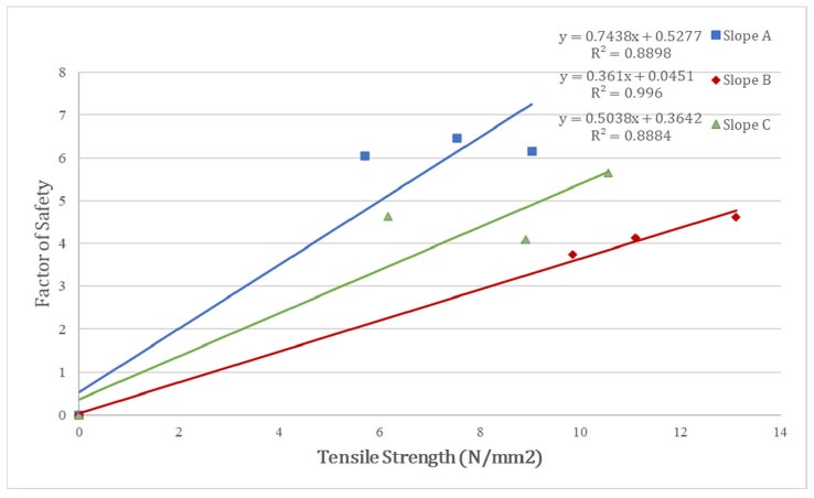
FOS from plaxis 3D against tensile strength (N/mm2).
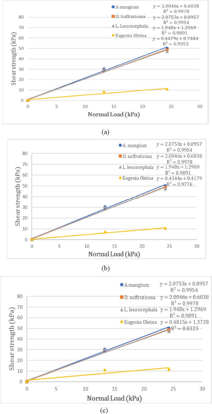
Comparison of shear strength of soil with eugenia oleina at: (a) slope A; (b) slope B; (c) slope C with other tropical plants at 13.3 kPa and 24.3 kPa.
CONCLUSION
This study investigates the physical and engineering properties of Eugenia Oleina and its implications for slope stability and erosion control. The research reveals that as the diameter of Eugenia Oleina increases, its tensile strength decreases, making it unsuitable for reinforcing slopes due to its shallow root structure. Compared to other tropical tree species, Eugenia Oleina exhibits the lowest tensile strength. While the additional cohesion provided by root tensile strength can enhance slope stability, the increase in the self-weight of the tree can compromise the stability.
The FOS analysis using Plaxis 3D indicates that planting Eugenia Oleina on slopes decreases the FOS, significantly increasing the risk of slope instability. Additionally, the decrease in the FOS of rooted soil over nine months suggests that surface erosion caused by Eugenia Oleina persists even after more than ten years. Therefore, planting Eugenia Oleina on slopes can lead to severe slope instability issues due to erosion.
To mitigate slope erosion and maintain stability in the study area, protective measures are necessary. Planting shrubs and grasses with low tensile strength is recommended to prevent surface erosion and enhance slope stability. The study highlights the inadequacy of Eugenia Oleina for slope reinforcement and stabilization and hence, suggests using it solely for landscaping purposes. To prevent debris erosion, incorporating additional grass beds or mulching techniques is more effective than relying on Eugenia Oleina plants. By employing simulation tools like Plaxis 3D with Mohr-Coulomb and Bishop methods, this research improves technical skills and understanding in the field of slope stability assessment.
LIST OF ABBREVIATIONS
| FOS | = Factor Of Safety |
| UMP | = Universiti Malaysia Pahang |
| FTKA | = Faculty of Civil Engineering Technology |
| ASTM | = American Society for Testing and Material |
| BS | = British Standard |
| AASHTO | = American Association of State Highway and Transportation Officials |
| TBF | = Tensile Breaking Force |
AVAILABILITY OF DATA AND MATERIALS
The data and supportive information are available within the article.


