All published articles of this journal are available on ScienceDirect.

Improving the Seismic Response of Tall Buildings: From Diagrid to Megastructures and Mega-Subcontrol Systems
Abstract
Background:
Diagrid structures, widely used for the tall buildings of the third millennium, are characterized by a very effective behaviour in the elastic field due to the grid triangulation. In particular, under horizontal actions, axial forces and deformations mainly arise in the structural members of the diagrid, thus resulting in the reduction of the shear lag effect and racking deformations. The response to incremental horizontal actions beyond the plastic threshold, however, shows a poor plastic redistribution capacity, with consequent low values of global ductility, in spite of a significant design overstrength.
Objective:
In this paper, it is proposed to exploit the high elastic efficiency of the diagrid type and use a vibration control system, based on mass damping mechanism with large mass ratios, to reduce a priori the inelastic demands due to seismic actions.
Methods:
Starting from the analysis of the seismic behavior of archetype diagrid buildings, a case study is selected to assess the effectiveness of the proposed motion-based design approach. For this purpose, the diagrid is first transformed into a megastructure (MS) configuration by densifying the diagonal elements at the most stressed corner areas and transfer floors, suitably chosen. Then, the exterior mega-frame is detached from interior sub-structures, thus allowing for a relative motion between the two structural portions according to a “mega-sub-structure control system” (MSCS), which activates the mass damping mechanism.
Results:
Time-history analyses carried out on simplified lumped-mass models confirm the effectiveness of the proposed strategy in reducing the seismic response.
Conclusion:
Finally, the practical feasibility of the MSCS and engineering solutions for the relevant structural organization are discussed.
1. INTRODUCTION
Diagrid structures can be considered the ultimate solution in the evolution of tube applications [1-3]. Widely used today, diagrids are perimeter configurations characterized by a narrow grid of diagonal members that act both as inclined columns and as bracing elements, thus carrying gravity loads as well as lateral forces. Due to the triangulated pattern, mainly internal axial forces arise in the members, thus minimizing the shear lag effect and the racking deformation component [4-6].
The wide use of diagrids for tall buildings is justified by both structural and architectural reasons. Due to the predominant axial stress and deformation regime, the diagrids provide high stiffness and resistance, thus allowing for achieving the required performance with reduced material consumption, as compared to other structural systems [1, 3]. Furthermore, the triangular mesh allows for tessellating any surface, thus adapting to complex shapes and geometries of building facades.
The pure triangular grid and its structural efficiency is the most distinctive aspect of diagrid, which also makes the system unique in its kind; on the other hand, the triangular grid makes difficult the application of the “capacity design” approach widely used as a basis for ductile design under seismic actions. In fact, it is not possible to distinguish the dissipative structural elements, i.e., weak elements, that provide ductility and dissipation capacity from non-dissipative structural elements, i.e., strong elements that retain elastic strength and provide bearing capacity for gravity loads, even in thepresence of widespread seismic damage.
Some recent studies [7-12] have dealt with the evaluation of the nonlinear behaviour of diagrids under seismic actions, with numerical analyses performed to derive indications on ductility and overstrength. The results invariably highlight a poor load redistribution capacity in the plastic field, with consequent very low global ductility values, despite considerable redundancy and overstrength.
Firstly, Baker et al. [7] proposed a methodology for deriving the values of seismic design performance factors by selecting an 8-story steel diagrid building as an archetype model. Nonlinear static analyses based on FEMA 450 procedures have been implemented in order to determine the overstrength and period-based ductility factors. Several diagrid systems with various diagonal slopes have been investigated by means of nonlinear static and dynamic analyses [8, 9], and the performance of diagrid structures with Buckling Restrained Braces (BRB) has also been evaluated [8, 10]. A further contribution to the quantification of seismic performance factors of steel diagrids has been provided by Heshmati and Aghakouchak [11], who have also observed that when the slope of the edge diagonal elements increases, the overstrength decreases, and the ductility of the overall system also increases. By recalling the previous studies, Asadi and Adeli [12] provide a comprehensive investigation of the seismic performance of diagrid structures by considering several archetype groups of diagrid buildings by varying the height, from 4 to 30 storeys, and by researching the optimal diagonal angle of the braces. They used nonlinear static, time-history dynamic, and incremental dynamic analyses for assessing diagrid performance and collapse mechanisms under seismic loads.
In this paper, a different design approach to bypass the problems related to the poor inelastic performance of diagrids under seismic action is proposed. In particular, an innovative scheme based on “controlled motion between building parts” is utilised for generating inertial damping that reduces the global dynamic response of the building, thus preserving the elastic behaviour of structural elements and minimizing the occurrence of damage to building components and contents. Starting from the observation that the diagonals in the corner zones of tall diagrids are the most stressed elements (due to the governing flexural behaviour and the effect of the overturning moment), the diagrid tube structure is firstly transformed into a diagrid Mega-Structure (MS). In particular, the diagrid mesh is densified at corner zones and transfer levels to create mega-columns and mega-beams, respectively, thus generating a diagrid Mega-Frame that provides global stiffness and strength. Then, the interior part of the building is subdivided into secondary substructures, each located between two consecutive mega-beams. Finally, the secondary substructures are seismically isolated at their bases; the isolation system allows for relative motion between the exterior mega-frame and the interior substructures, which gives the possibility to control the seismic response according to the so-called “Mega-Sub Controlled System” (MSCS), firstly proposed by Feng and Mita in 1995 [13].
In the following, the seismic behavior of diagrid tall buildings is firstly investigated by varying the building aspect ratio and the diagonal slope, and a case study is selected for generating the MS and MSCS solutions. Simplified MSCS lumped-mass models are then utilized for exploring the potentials of the proposed design schemes, based on the concept of mass damping and employing seismic isolation for converting large building portions (the secondary substructures) into vibration absorbers. Finally, engineering solutions for the structural organization of the MSCS are discussed.
It is worth underlining that, while several conceptual studies are provided in literature for MSCS applications [14-24], such schemes are not yet proposed for diagrid tall buildings. Furthermore, while this study refers to MSCS, the concept can be generalized, and other real-scale applications can be envisaged in the context of a new design paradigm that can be appointed as motion-based design by sub-structuring. Although such solutions may initially cost slightly more, they are cost-effective in the life cycle perspective due to the lower earthquake impact (i.e., losses and damage, repair costs, disruptions, and related consequences).
2. METHODS
2.1. Seismic Behaviour of Diagrids
2.1.1. Archetype Diagrid Buildings
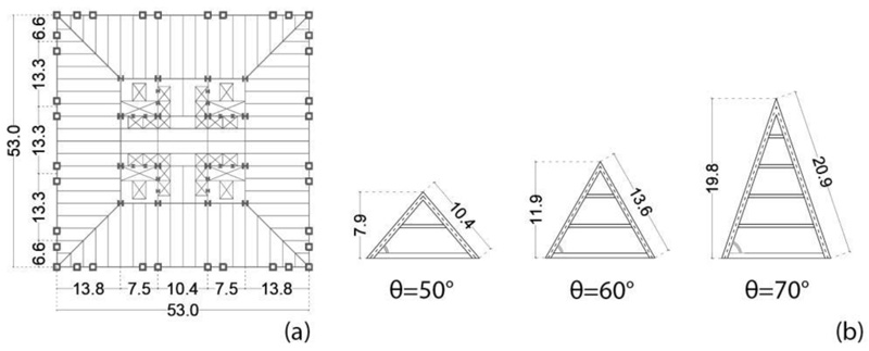
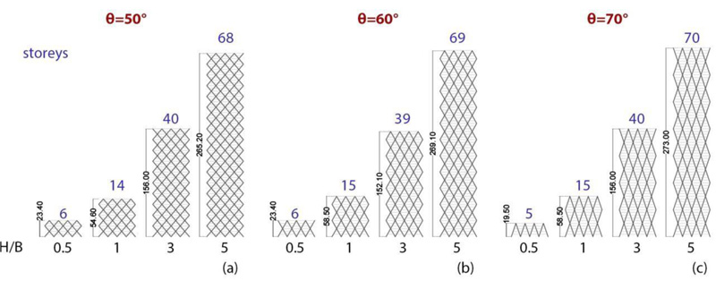
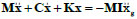
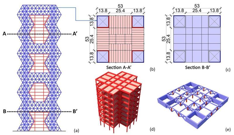
Three groups of archetype buildings (Fig. 1) are considered to represent a wide range of applications, from low- to high-rise diagrid buildings. Such groups refer to different diagonals’ angles θ of the triangular module, i.e., 50°, 60°, 70°; for each group, four aspect ratios H/B, i.e., 0.5, 1, 3, 5, and the same square plan 53 x 53 m are selected (Fig. 2a) [25, 26]. The number of storeys and the height of the buildings are shown in Fig. (1). The triangular modules with the relevant diagonal length and module height are provided in Fig. (2b), showing that the number of storeys of the module is equal to 2, 3, and 4, respectively, for θ equal to 50°, 60°, and 70°. The material used for the diagrid is S275 steel (fyk = 275 MPa, ftk = 430 MPa). The dead and live gravity loads are 5 kN/m2 and 3 kN/m2, respectively. The design seismic action is derived according to Eurocode 8, as specified in the following subsection. Both linear dynamic and nonlinear static analyses are carried out on the archetypes’ 3D FE models using the software SAP2000 [27].
2.1.2. Linear Dynamic Analysis
For the evaluation of the design seismic action, the design acceleration response spectrum prescribed by Eurocode 8 [28] is assumed, characterized by 10% exceedance probability in 50 years, for high seismicity zone (ag = 0.35 g), soil type B (S = 1.2; TB = 0.15 s; TC = 0.5 s; TD = 2 s), and damping ratio equal to 0.05. The behaviour factor q is assumed equal to 3, according to Kim and Lee [8].
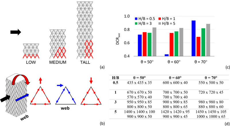
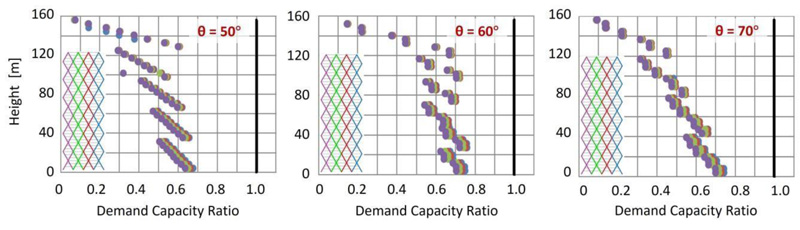
The main results of the elastic analysis are provided in Fig. (3), by considering the axial forces due to the combined effect of compression gravity loads and shear and bending moment induced by the lateral actions. By considering the “web” building façades, i.e., the façades parallel to the applied lateral action (Fig. 3b), the location of the most stressed diagonals (depicted in red) is shown in Fig. (3a). As the building becomes taller, the bending mode governs more than the shear mode. Therefore, for low-rise buildings, the most stressed elements are all the diagonals at the base, while for high-rise buildings, they are the corner diagonals. The average values of the Demand to Capacity Ratio, DCRave, and the minimum and maximum cross-sections of the diagonals are provided in Fig. (3c and d), respectively.
2.1.3. Non-Linear Static Analysis
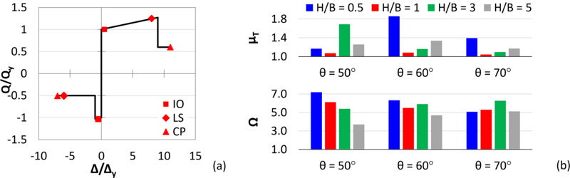
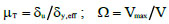
In order to evaluate the overstrength and ductility of the diagrid buildings subjected to seismic actions, pushover analyses are carried out by assigning axial plastic hinges to the diagonals according to the model proposed by ASCE 41-13 [29] for diagonals of concentric brace frames (Fig. 4a). For this purpose, two seismic performance factors are introduced and depicted in Fig. (4b) for each group of archetypes, i.e., the ductility µT and the overstrength factor Ω, given by Eq. 1:
 |
(1) |
Where δy,eff, δu, and Vmax, are the effective yield drift, the ultimate roof drift, and the maximum base shear, obtained from the pushover curve linearized according to the methodology of FEMA P695 [30]; V is the design base shear. From the results of the pushover analyses, it can be stated that the diagrid systems are characterized by great overstrength and poor global ductility, which are in line with the outcomes provided in the current literature [7-12] (see §1).
2.1.4. Focus on the Case H/B = 3
For a better insight into the seismic performance of the diagrid systems, more detailed results are provided in Figs. (5 and 6), by assuming H/B = 3 and varying the diagonal’s angle. By observing the distribution of the DCR along the height of the building obtained from the elastic analysis (Fig. 5), it is shown that the diagonals at the base corner are the most stressed elements for each diagonal’s angle. In addition, the pushover curves, depicted in Fig. (6a), highlight the poor redistribution capacity of the diagrid systems, for example, by observing the sequence of plastic hinges for θ = 60° (Fig. 6b) with maximum plastic deformation demands concentrated in the corner zone. The crucial role of the corner diagonals with respect to the other members is therefore evident, both in the elastic range, in terms of internal force distribution, and in the plastic range, in terms of deformation demand.
2.2. Proposed Strategy
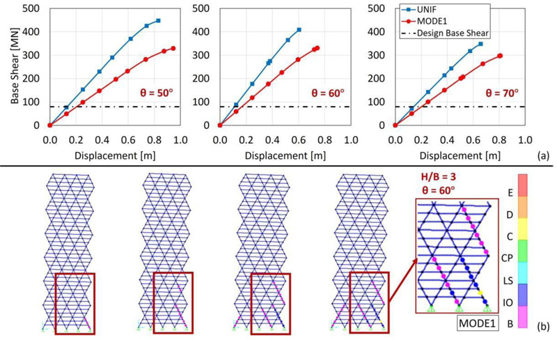
Diagrid structures are becoming very popular for buildings in seismic areas, even of medium-low height, for which the requirements of ductility and dissipation capacity are of primary importance. In these cases, the problem of seismic resistance is usually solved by using either a dual system, i.e., by coupling a ductile reinforced concrete core to the exterior diagrid (e.g., Guangzhou West Tower [1, 31-33]), or by equipping the diagrid buildings with base isolation system (e.g., the Sony City [34] and Prada Boutique Aoyama [35, 36] buildings in Tokyo). In both solutions, diagrids are designed to remain in the elastic range. Other researchers [8, 37-39] suggest the adoption of either shear links (Fig. 7a) at the diagrid nodes or BRB systems as diagonal members (Fig. 7b).
In this paper, the authors propose a different idea to transform the diagrid structure into a diagrid megastructure (MS) by reinforcing the most stressed corner zones by densifying the grid. The resulting MS configuration consists of exterior diagonalized mega-columns, continuous along the building elevation and laced together at discrete levels by diagonalized mega-girders (every tenth – fifteenth – twentieth floors), to form an integral unity of great strength, stiffness, and stability. The interior part of the building is subdivided into several independent secondary substructures, each one extending between two mega-girders and designed for transferring the gravity loads to the mega-columns through the mega-girders.
From the MS configuration also derives the possibility of controlling the seismic response of the building by adopting the so-called Mega-Sub-Controlled System (MSCS), where, according to an idea proposed by Feng and Mita in 1995 [13], the relative motion between the exterior mega-frame and the interior substructures is allowed, giving rise to a mass damping effect.
3.1. From Diagrids to Megastructures
3.1.1. Megastructures (MS): High-Efficiency Structural Systems for Tall Buildings
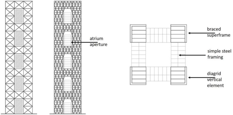
The concept behind megastructures was initially formulated by Fazlur Khan based on three static requirements [40-42]: (1) to transfer as much as possible, if not all, the compression gravity load into the mega-columns, thus stabilizing the building structure against overturning moments caused by lateral loads; (2) to position the mega-columns at the planned perimeter, thus maximizing the bending stiffness of the building; (3) to interconnect the columns with a stiff shear resisting structural system, thus forcing the columns to work as an integrated system. These three requirements give rise to mega-frame structures, having the form of a multi-story portal placed on the exterior of a building. The exterior mega-frame consists of mega-columns arranged in the corners of the building, connected by mega-beams every 10-15 storeys; each interior substructure spans 10-15 storeys between two mega-beams. The mega-beams, at least one story deep, also act as transfer trusses, supporting the columns of the interior substructures and transferring the relevant gravitational load to the exterior mega-columns. Some megastructure configurations are shown in Fig. (8) [43]. In particular, the vertical and horizontal mega-elements of the diagonalized façades are rigidly connected to each other and very stiff in their plane. Hence, an equivalent cantilever beam is obtained, having the same efficacy as a tubular system.
A seminal study by Fazlur Khan provides the mega-frame concept applied to the Chicago World Trade Center project, a tower of 170 storeys, 655 m high, 706,000 m2 of gross floor area. Although never built, this project has had great importance in the evolution of the structural systems of tall buildings. Fazlur Khan [41] proposed to go from a multi-column tube to a square tower with four giant corner mega-columns. Hence, the moment of inertia and the effective section modulus of the new configuration increase, consequently improving the structural efficiency. Approximately every 20 floors, exterior and interior transfer trusses carry the gravity loads into the four mega-columns that are also utilized as service cores for the building.
3.1.2. Mega-Frame Configurations Applied To A Case Study
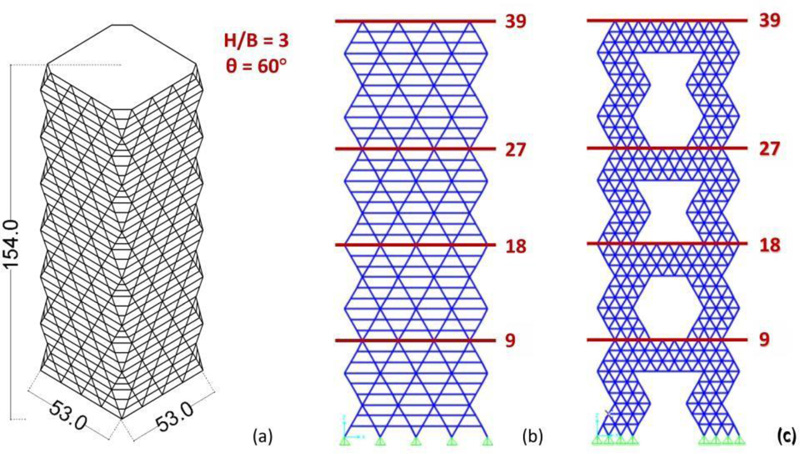
In order to show the proposed strategy, a case study is selected from the groups of archetypes described in the previous Section 2.1, i.e., the 39-storey building with H/B = 3 and θ = 60°, 154 m tall (Figs. 1, 2 and 9a).
The design seismic action is estimated by assuming the same design spectrum adopted in Section 2.1. Based on the results of the response spectrum analyses (RSA) performed on the 3D FEM model of the DiaGriD structure (DGD) (Fig. 9b), the cross-sections derived for the different members are shown in Table 1. Then, two MegaStructure (MS) solutions, appointed as MS1 and MS2, are define using diagrid densification. The MS FEM model of the two variants is shown in Fig. (9c), while the cross-sections adopted for the structural members are provided in Table 1. In particular, the MS1 and MS2 models are both obtained by increasing the density of diagonals at corner areas and at four horizontal levels, which subdivide the building into four zones, the first three of 9 storeys, while the top one of 12 storeys. In the MS1 solution, the cross-sections of diagonals and beams are the same as in the DGD model. In the MS2 solution, instead, the cross-sections utilised for the members at levels 19-27 in the DGD model are adopted throughout the structure.
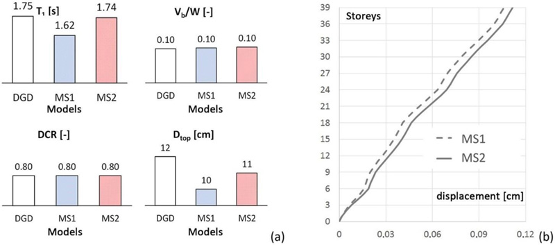
The accuracy of the structural sizing in terms of stiffness and strength of the proposed structural solutions MS1 and MS2 has been verified by carrying out response spectrum analyses. For the sake of brevity, only the main analysis results are reported in Fig. (10) and compared to the DGD model, in terms of: fundamental period, T1; base shear, derived from the RSA and normalized to the overall weight of the structure, Vb/W; maximum DCR of the diagonals; top displacement, Dtop; lateral drifts along the height.
3.2. From Megastructures to Mega-Substructure Control Systems
A typical mega-frame exhibits dramatic structural efficiency from the static point of view by providing high stiffness and strength while minimizing the amount of structural materials. Taking advantage of this structural configuration, Feng and Mita [13, 44-47] first, and then other authors [15-22, 47-49] proposed the so-called mega-substructure control system (MSCS), a solution that shows equally dramatic efficiency also from the dynamic point of view. In the MSCS, indeed, the hierarchical organization in primary and secondary substructures is retained and exploited for activating the relative motion between the two structural portions (primary and secondary structures) and the consequent large-mass damping effect. Feng and Mita analyse the MSCS through a simplified 2-DOF lumped mass model and, by minimizing the variance of the displacement of the first degree of freedom (primary structure), they provide the optimal values for the design parameters, namely, the damping ratio of the absorber (secondary substructure) and the ratio between the frequencies of the absorber and primary structure. In the following, the formulation proposed by Feng and Mita is briefly recalled and subsequently used to transform the MS1 and MS2 solutions into MSCS solutions.
3.2.1. Vibration Control System Proposed By Feng And Mita
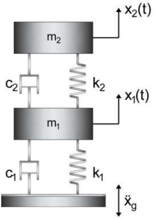
The two-degree-of-freedom (2DOF) model of the MSCS is depicted in Fig. (11), where m, k, and c denote mass, stiffness, and damping coefficients, respectively, and subscripts “1” and “2” refer to the primary system, respectively, i.e., the megastructure, and to the absorber, i.e., the secondary substructures.
| Elements | Floors | DGD e MS1 Models | MS2 Model |
|---|---|---|---|
| Beams | 0-9 | 450x450x50 | 350x350x40 |
| 10-18 | 450x450x40 | 350x350x40 | |
| 19-27 | 350x350x40 | 350x350x40 | |
| 28-39 | 350x350x30 | 350x350x40 | |
| Diagonals | 0-9 | 900x900x85 | 800x800x75 |
| 10-18 | 900x900x75 | 800x800x75 | |
| 19-27 | 800x800x75 | 800x800x75 | |
| 28-39 | 800x800x65 | 800x800x75 |
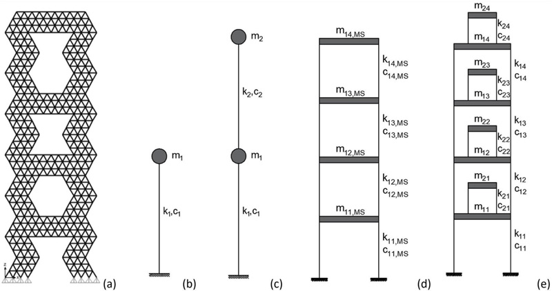
The equations of motion of the system under seismic excitation are written in the matrix form (Eq. 2):
 |
(2) |
Where: M, C, K refer, respectively, to the (2x2) mass, damping and stiffness matrices; x = {x1 x2}T is the vector (2x1) of relative displacements of the structure with respect to the ground; I = {1 1}T is the vector that multiplies the ground acceleration ẍg.
The natural frequencies and damping ratios of megastructure and substructure are defined as follows (Eq. 3):
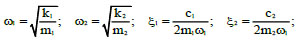 |
(3) |
with the damping ratio of the substructure ξ2 defined as a function of ω1. The mass ratio and frequency ratio are represented by the following parameters (Eq. 4):
 |
(4) |
By modelling the earthquake excitation as a white noise input, Feng and Mita [13] impose the minimization of the variance of the displacement of the first degree of freedom, with respect to two design variables, i.e., the frequency ratio β and the damping ratio ξ2, whose optimal values are provided in closed form in Eq. (5). It is worth noticing that in the expression of the optimal damping ratio ξ2opt, the frequency ratio β is not explicitly expressed as the optimal value, thus allowing for selecting an appropriate value for β within practical design ranges.
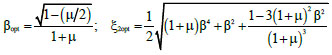 |
(5) |
3.3. Design of the Mega-Substructure Control System
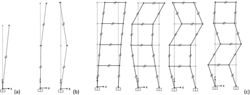
The passive control schemes based on MSCS configuration for the case-study MS1 and MS2 are obtained according to the following design procedure. Starting from the dynamic properties of the 3D FEM MS models of the uncontrolled megastructure configurations MS1 and MS2 (Fig. 12a), the equivalent reduced-order SDOF models (SDOF MS) (Fig. 12b) are derived. The optimal values of the frequency ratio βopt and damping ratio ξ2opt are then calculated according to Eq. (4), thus defining the dynamic characteristics of the secondary system in the 2DOF MSCS configurations (Fig. 12c). In order to assess the accuracy of the SDOF and 2DOF models, more refined MDOF models of the uncontrolled and controlled configurations, i.e., 4DOF MS and 4+4 DOF MSCS models (Fig. 12d and 12e), are also defined. Finally, modal and time-history analyses are carried out to compare the seismic response of the controlled and uncontrolled configurations.
3.3.1. Dynamic Characteristics Of Lumped Mass Models
The mass m1, stiffness k1, and damping coefficient c1 for the SDOF MS model depicted in Fig. (12b) are evaluated from the corresponding properties of the reference 3D FEM MS model, provided in Table 2, by recalling that m1 is the total mass of the MS configuration, appointed as Mtot in Table 2, while k1 is equal to ω12m1 and c1 is calculated as 2ξ1ω1m1.
For the 2DOF MSCS models (Fig. 12c), the total mass Mtot is distributed between the megastructure and substructure, as a function of mass ratio μ, i.e., m1 = Mtot/(1+μ), m2 = μm1. Once defined the value of m1, the period T1 (and the frequency ω1) of the first DOF, representing the exterior mega-frame, is assumed equal to the MS model counterpart, therefore: k1 = ω12m1 and c1 = 2ξ1ω1m1. The stiffness k2 and the damping coefficient c2 of the second DOF, representing the secondary substructures, are evaluated starting from the optimal parameters βopt and ξ2opt, i.e., k2 = ω22m2 and c2 = 2ξ2optω1m2, with ω2 = βoptω1. In particular, assuming a mass ratio equal to 1, the optimal values of the parameters are: βopt = 0.35 and ξ2opt = 0.15 (Table 3). Hence, the period values of the substructure T2 are obtained, i.e., 4.59 s and 4.91 s for the MS1 and MS2 models, respectively (Table 3). It is worth observing that such period and damping values, T2 and ξ2, can be easily obtained by means of a seismic isolation system at the base of each substructure.
| Model | n [-] | Mfloor [kNs2/m] | Mtot [kNs2/m] |
T1 [s] |
ω1 [rad/s] |
ξ1 [-] |
|---|---|---|---|---|---|---|
| MS1 | 39 | 2234 | 87120 | 1.62 | 3.87 | 0.05 |
| MS2 | 39 | 2194 | 85564 | 1.74 | 3.62 | 0.05 |
| Model |
βopt [-] |
ξ2opt [-] |
T1 [s] |
T2 [s] |
ω1 [rad/s] |
ω2 [rad/s] |
ξ1 [-] |
|---|---|---|---|---|---|---|---|
| MSCS1 | 0.35 | 0.15 | 1.62 | 4.59 | 3.87 | 1.37 | 0.05 |
| MSCS2 | 1.74 | 4.91 | 3.62 | 1.28 |
| Mode | SDOF MS2 | 2DOF MSCS1 | SDOF MS2 | 2DOF MSCS1 | ||||
|---|---|---|---|---|---|---|---|---|
| T [s] | Γ [-] | T [s] | Γ [-] | T [s] | Γ [-] | T [s] | Γ [-] | |
| 1 | 1.62 | 1.00 | 4.92 | 0.62 | 1.74 | 1.00 | 5.25 | 0.62 |
| 2 | - | - | 1.52 | 0.38 | - | - | 1.63 | 0.38 |
| Mode | 4DOF MS1 | 4+4 DOF MSCS1 | 4DOF MS2 | 4+4 DOF MSCS2 | ||||
|---|---|---|---|---|---|---|---|---|
| T [s] | Γ [-] | T [s] | Γ [-] | T [s] | Γ [-] | T [s] | Γ [-] | |
| 1 | 1.62 | 0.76 | 4.87 | 0.47 | 1.74 | 0.78 | 5.22 | 0.49 |
| 2 | 0.65 | 0.16 | 4.64 | 0.08 | 0.69 | 0.15 | 4.96 | 0.07 |
| 3 | 0.40 | 0.05 | 4.61 | 0.03 | 0.43 | 0.05 | 4.93 | 0.02 |
| 4 | 0.27 | 0.03 | 4.60 | 0.02 | 0.30 | 0.02 | 4.92 | 0.01 |
| 5 | - | - | 1.53 | 0.29 | - | - | 1.64 | 0.30 |
| 6 | - | - | 0.64 | 0.08 | - | - | 0.69 | 0.07 |
| 7 | - | - | 0.40 | 0.03 | - | - | 0.43 | 0.02 |
| 8 | - | - | 0.27 | 0.01 | - | - | 0.30 | 0.01 |
In the four-degree-of-freedom megastructure model (Fig. 12d), appointed as 4DOF MS, the i-th mass, stiffness, and damping coefficients of the megastructure are denoted by m1i,MS, k1i,MS, and c1i,MS (with i = 1, …, 4). The i-th mass is equal to the product of the total number of floors in the i-th mega-frame segment, nfr,i, and the floor mass, Mfloor, i.e., m1i,MS = nfr,i·Mfloor. The stiffness coefficients k1i,MS of the four degrees of freedom of the mega-frame are evaluated according to the procedure of Connor and Laflamme [50], by assuming a stiffness distribution corresponding to the fundamental modal shape of the 3D FEM model. For the damping factors, the same value of the MS configurations is assumed, namely ξ1 = 0.05.
With reference to the 4+4 DOF MSCS model, the i-th mass, stiffness, and damping coefficients of the megastructure are appointed as m1i, k1i, c1i, while the substructure counterparts are appointed as m2i, k2i, c2i. For the sake of simplicity, all substructures are assumed equal. The i-th mass of the 4DOF MS model is distributed between megastructure and substructure as a function of the mass ratio μ. The i-th mass of the megastructure is m1i = m1i,MS/(1+μ), while the mass of the i-th substructure is m2i = μm1/nframe, with m1 = Σim1i. The i-th stiffness of the megastructure and substructure are derived assuming that the periods (and circular frequencies) are equal to the counterparts of the 2DOF MSCS model (T1 and T2, ω1 and ω2, provided in Table 3). It follows that: k1i = k1i,MS/(1+μ) and k2i = ω22m2i.
3.3.2. Modal Analyses
Modal analyses are carried out on the four models (SDOF and 4DOF MS, 2DOF and 4+4 DOF MSCS). Since the damping values of the megastructure and substructures are different, respectively equal to 0.05 and 0.15 (Table 3), the MSCS is characterized by non-proportional damping. In particular, a viscous system that is not classically or non-proportional damped exhibits complex natural modes and does not satisfy the Caughey and O 'Kelly identity: CM-1K = KM-1C [51]. Therefore, non-diagonal elements in the C-matrix cannot be neglected. Hence, in order to decouple the equations of motion, the state-space formulation is developed.
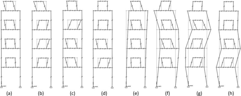
By considering the undamped system, the modal shapes of the SDOF MS, 2DOF MSCS, 4DOF MS, 4+4 DOF MSCS models, obtained using SAP2000 software [27], are shown in Figs. (13a-c and 14), respectively. The corresponding values of periods and participating masses are given in Tables 4 and 5. Looking at the periods and the participating masses of the SDOF MS and 2DOF MSCS models (Table 4), it should be observed that the first mode of the MSCS model is the mode of the substructure, while the second mode represents the mode of the megastructure. For μ=1, although the total mass is divided equally between the two structural parts, a participating mass of the fundamental mode greater than 0.50 is activated, equal to 0.62.
By observing the periods and participating masses of the 4DOF MS and 4+4DOF MSCS models (Table 5), as well as the relevant vibration modes (Figs. 13c and 14), it should be pointed out that the first four modes of the MSCS model are the substructure modes, while the subsequent four modes are the megastructure modes. The comparison between the SDOF and MDOF MS models shows a perfect agreement of the fundamental period. Similarly, the first and fifth periods of the MDOF MSCS model are close to the first and second periods of the 2DOF MSCS model (MSCS1: 4.87 s vs. 4.92 s, 1.53 s vs. 1.52 s; MSCS2: 5.22 s vs. 5.25 s, 1.64 s vs. 1.63 s). This correspondence is also observed in terms of participating mass. Indeed, the sum of the first four modal participating masses of the 4+4DOF MSCS model is approximately equal to the first participating mass of the 2DOF model (MSCS1: 0.59 vs. 0.62; MSCS2: 0.60 vs. 0.62). The sum of the participating masses of the next four modes is approximately equal to the second participating mass of the 2DOF model (MSCS1: 0.41 vs 0.38; MSCS2: 0.40 vs 0.38).
As regards the non-classically damped system, modal analyses are only carried out on the 2DOF MSCS model. The periods and damping ratios, derived from the complex modal analysis, of models MSCS1 and MSCS2 are given in Table 6. The following observations can be made. The values of damping are the same for the two models since for both models, a mass ratio μ equal to 1 is assumed. Since the first vibration mode mainly involves the substructure and the second mode mainly involves the megastructure, by combining the two structural parts, a reduction is obtained for the damping in the first mode (from 0.15 to 0.124) and an increase in the second mode (from 0.05 to 0.107). The comparison between the Tables 4 and 6 suggests that the periods derived from classical and complex modal analyses are almost coincident.
| - | 2DOF MSCS1 | 2DOF MSCS2 | ||
|---|---|---|---|---|
| Mode | T [s] | η [-] | T [s] | η [-] |
| 1 | 4.92 | 0.124 | 5.28 | 0.124 |
| 2 | 1.52 | 0.107 | 1.64 | 0.107 |
3.3.3. Time History Analyses
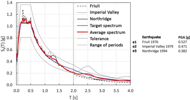
Time-history analyses are carried out by adopting a set of three spectrum-compatible ground motions, defined using SeismoMatch software [52], which selects accelerograms by matching their average response spectrum to a reference elastic spectrum (here, the one prescribed by Eurocode 8 [28]). In Fig. (15), the acceleration spectra with the relative PGA values are reported, as well as the average and the reference spectra.
The time history analyses are carried out by assigning the damping ratio as a function of the periods, according to the following considerations. Recalling that the first vibration modes are the modes of the substructures, while the next ones mainly involve the megastructure (Fig. 14), and considering the values of complex modal damping provided in Table 6, then the damping ratio of 0.124 is assigned to the first four modes, while the damping ratio of 0.107 is assumed for the following ones.
The results of the time-history analyses are provided in terms of top displacement and acceleration and base shear. With reference to the peak values of these response parameters, three performance indexes are introduced for a preliminary estimation of the effectiveness of the MSCS:
1. dtop, the ratio between the top displacements of the controlled and uncontrolled structures, dtop=dtop,MSCS/dtop,MS.
2. atop, the ratio between the top absolute accelerations of the controlled and uncontrolled structures, atop=atop,MSCS/atop,MS.
3. v, the ratio between the base shear forces of the controlled and uncontrolled structures, v=Vb,MSCS/Vb,MS.
The values of the top displacement and acceleration ratios for each accelerogram and MDOF model, as well as the average value, are shown in Fig. (16a and b), respectively. Similarly, base shear ratio values are reported in Fig. (17a and b) for MS and MSCS models 1 and 2, respectively. The results provided in Fig. (17), in terms of base shear ratio v, obtained by adopting both pairs of SDOF MS – 2DOF MSC and MDOF MS – MDOF MSC models confirm the accuracy of the simplified models in the first design phase. In fact, a close correspondence between the simplified 2DOF or SDOF models and the respective MDOF models is registered, with scatters in terms of average values of 1% and 7%, for solutions 1 and 2, respectively.
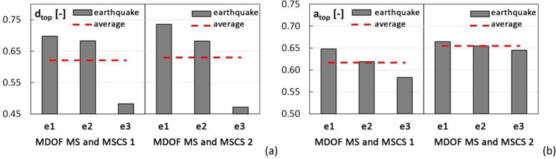
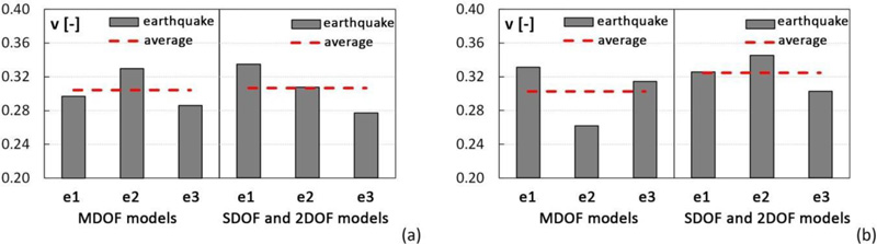
From the results depicted in Figs. (16 and 17), it should be emphasized that the passive control of the megastructure induced by the substructures results in a dramatic reduction of the seismic response. In fact, in the MSCS1 configuration, the displacement and acceleration ratios are approximately equal to 60%, and the base shear ratio is about 30%. In the MSCS2 model, the displacement and acceleration ratios are equal to 65%, and the base shear ratio is about 30%.
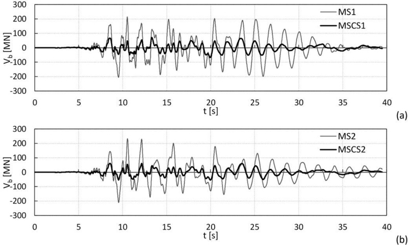
Moreover, as an example, the base shear time histories of the controlled and uncontrolled configurations (models MDOF 1 and 2) for the Imperial Valley ground motion are compared, as shown in Fig. (18a and b). The plots confirm that the passive control of the megastructure using the substructures’ mass damping effect results in a substantial reduction of the overall seismic response.
Although the results of these dynamic analyses refer to a single case study and MSCS configurations derived from the same optimal values of design parameters, they are representative of more general applications. These outcomes, in fact, are in line with the previous studies [53, 54], in which different structural solutions are considered by varying the building’s fundamental period, i.e., going from very rigid (e.g., stiff diagrid structures or diagonalized mega-frame) to more flexible structural systems (e.g., moment-resisting frames or frame tubes). Then, by adopting 2DOF and MDOF lumped mass models, the dynamic behaviour of MSCS configurations is evaluated by varying all design parameters (μ, T2, ξ2) in a wide range. The effect of the distribution of moving secondary substructures is also investigated [54].
3.4. Engineering Solutions
While real tall buildings utilizing the megastructure concept have been already built, applications of Mega-Substructure-Control Systems have not yet been realized properly. In the previous section, it has been shown that this configuration gives rise to a highly desirable response of tall buildings under seismic loads and a dramatic improvement of the performance with respect to conventional solutions. The analyses have been carried out on lumped-mass models, which are able to predict the dynamic response and highlight the major behaviour aspects. However, it is interesting to understand how the MSCS design concept can be translated into actual engineering solutions. For this aim, a brief discussion on the design issues is provided concerning the structural solutions suggested in the literature [14-24]; finally, a schematic design solution is proposed for the case study.
3.4.1. Structural Organization Of MSCS And Relevant Design Criteria
The MSCS concept starts from the mega-frame structural typology, composed of primary mega- columns and mega-girders, which resists both gravity and lateral loads due to the frame action, and a number of secondary substructures, 10-15 storeys tall, that are placed between two mega-beams and are only designed for their gravity loads. The substructures, indeed, rely on the mega-frame stiffness and strength due to the floor diaphragm action. In the case of the MSCS, instead, a detachment between exterior mega-frame and interior substructures is required for allowing the relative motion, which also requires a physical separation in the floor slab. Therefore, the secondary structures should possess adequate lateral strength and stiffness, necessary to absorb internal force demand and maintain drifts within the serviceability limit. In general terms, the engineering solutions that guarantee the expected behaviour and the construction feasibility of the MSCS should account for the following issues:
1. The “physical” detachment of the parts of the building that must work as substructures from the megastructure, and the subdivision of the building mass between megastructure and substructure.
2. The relative motion between substructures and megastructures.
3. The stiffness and the damping of the substructures, defined by the optimal value derived from optimization procedures [13, 53, 54] or parametric analyses [53, 54].
The disconnection between the main and secondary structures requires a joint (gap) in each floor slab, whose position depends on the percentage of the tributary mass of primary and secondary structures, which, in turn, should be compatible with construction aspects and functional requirements. The size of the gap should be larger than the maximum relative displacement predicted by the analyses. With reference to the design of the substructures, it is necessary to define a structural system which bears the floors’ weight and possesses adequate lateral stiffness. In Section 3.3, seismic isolation system at the base of the substructures is the strategy preliminarily suggested for dividing the design process of the substructure into two independent parts, each related to a specific function: (1) the design of the isolation system, aimed at tuning the substructure mass at the optimal frequency, and making it works as a tuned mass damper; (2) the design of the structural system, aimed at ensuring safety and serviceability of the substructures, as inhabited parts of the building. As a result of the analyses carried out by the authors in other studies [53, 54], an additional option emerges to design the substructure without taking into account the optimal frequency value, since, due to the large mass ratio, the response of the megastructure is highly reduced in the whole range of typical isolation periods.
Concerning the damping associated with substructures, which is essential for mitigating the displacement of the substructure and avoiding the occurrence of collision with the exterior mega-frame, different strategies can be considered, namely:
1. Installing dampers between the megastructure and the substructure [16].
2. Inserting a tuned-inerter-damper between the megastructure and the substructure [24].
3. Including dampers in the substructures [22].
4. Adopting an isolation system at the base of the substructures made either of high damping rubber bearings, or by coupling isolators and viscous (or hysteretic) dampers.
Another engineering aspect that must be properly addressed in order to make the MSC configuration feasible concerns the floor structural system at the transfer levels. Its role is fundamental, and its design is challenging: it should span the large bay between the corner mega-columns (say, 20-30 m, or more), bear the gravity load of the upper substructure (10-15 storeys tall), and transfer this load to the mega-columns. Therefore, the design solutions should account for very long and heavily loaded free spans. A system made of two-ways mega-truss girders seems a very good candidate. Finally, from a functional and architectural point of view, it should be recalled that both the classical typology of mega-frame and the innovative MSCS usually assume that the mega-columns, which are the only vertical continuous structures, are located at the building corners. For this reason, it is implicitly assumed that the vertical transportation system (elevators, escalators, as well as staircases) is concentrated in the corner locations, thus implying that the classical core-centred floor plan should be rearranged in a solution with split corner cores.
As an example, two MSCS engineering solutions, based on the concept of mass damping, are briefly described.
The first structural solution is proposed by several papers [14-16, 18, 23] and is obtained first from the Tokyo City Hall, an emblematic mega-frame, 144 m tall, composed of steel truss mega-columns and mega-girders that subdivide the building into three mega-zones, each of 48 m. In the MSCS solution, a gap of 0.5 m separates the external mega-frame to two or three interior substructures. The bases of such substructures are fixed to the mega-beams structures of the mega- frame at the transfer floors. Viscous or friction dampers are utilized, either between the exterior and interior structures or within the substructures according to different arrangements. Additional columns are introduced between the mega-beams and the upper floors of the substructures by means of slip supporting joints in order to realize intermediate supports for the mega-beams.
The second structural solution is proposed by Martinez-Paneda and Elghazouli [21]. An exterior mega-frame, 250 m tall, is composed of four reinforced concrete corner mega-columns and steel mega-trusses that subdivide the building into five interior blocks. Each block is vertically stacked and overhangs alternately in the two plan orthogonal directions. The structural system of the interior blocks is a simple frame with hinged beams; thus, it leans on the mega-columns for lateral stability by means of the diaphragm action of the composite steel-concrete floor. A sliding joint is provided between the substructures floor and the core at each level, with a spring and a viscous damper connecting the two structural parts, in order to allow the relative motions between the exterior mega-frame and the interior blocks.
3.4.2. Proposed MSCS Schematic Solution For The Case Study
As discussed in Section 3.1, the mega-frame (Fig. 10c) consists of four continuous corner mega- columns and four mega-beams, each three storeys depth. Consequently, the mega-frame is made up of four blocks, with the first three ones 9 storeys tall and the last one of 12 storeys. In order to realize the controlled mega-substructure, it is planned to use the mega-columns as service cores and disconnect the substructure slabs by means of a joint at each floor (Fig. 19a-c). The continuity of the service cores along the building height gives rise to a cruciform floor plan for the substructure slabs (Fig. 19b and d); the columns of the substructures are connected at their bases to the mega- beams by means of the seismic isolation system. Finally, the mega-floors are made up of a two-way truss beam system (Fig. 19a, c, e).
CONCLUSION
This paper deals with an innovative scheme for diagrid tall buildings in seismic zones. The idea is to 625 reduce a priori the inelastic seismic demand on the diagrid by utilizing a vibration control system firstly introduced by Feng and Mita, i.e., the MSCS, based on mass damping mechanism with large mass ratios. For this purpose, starting from archetype diagrid buildings, a case study is selected. A megastructure is firstly defined by densifying the diagrid mesh at the corner zones. Then, the MSCS configurations are obtained by subdividing the building into an exterior megastructure and interior substructures isolated at their base. Linear dynamic analyses are carried out on simplified lumped mass models for assessing the effectiveness of MSCS to reduce the seismic response of diagrid buildings. Finally, the structural organization of MSCS and a schematic solution are proposed for the case study.
From the analysis of seismic behaviour of the archetypes, the following conclusive remarks can be drawn.
● Diagrid structures have limited plastic reserves, with poor ductility and redistribution capacity in the plastic field, despite the high structural redundancy of the grid and the significant design overstrength.
● For buildings with aspect ratio H/B equal to or larger than 3, the governing flexuralbehaviour and the effect of the overturning moment clearly point out towards the crucial role of the corner diagonals, both in the distribution of stresses in the elastic field and the sequences of plastic hinges formation.
● By following the flow of internal forces within the building façades, the diagrids are naturally directed towards MS solutions through the mesh densification at the corner zones (mega-columns) and transfer levels (mega-beams).
From the results of the dynamic analyses carried out on the simplified lumped mass models, it emerges that:
● Modal analyses of the MSCS models and their standalone portions (exterior megastructure and interior substructures) confirm the ability of the isolation systems to dynamically subdivide the building into a principal and several secondary systems.
● Time history analyses show that MSCS is able to drastically reduce the base shear, and both the top absolute acceleration and relative displacement of the megastructure.
● The mechanism of mass damping, emerging from the MSCS scheme without adding external masses, is characterized by a large mass ratio, thus guaranteeing great effectiveness in reducing the dynamic response and robustness to varying dynamic input.
While this study refers to MSCS, the concept can be generalized for real-scale applications. In fact, other solutions can be derived by adopting this new design paradigm, which can be appointed as motion-based design by sub-structuring. Such solutions can be considered cost-effective in the life cycle perspective because they reduce the seismic response and the earthquake impact.

