All published articles of this journal are available on ScienceDirect.

Proposing Cubic-Grid System as a New Structural System for Tall Buildings
Abstract
Background:
Changes in the skyline of cities all over the world show that tall buildings are an interesting solution to accommodating growth more sustainably in today’s urban areas. Stability against lateral loading is the main issue for designing high-rise buildings. Diagrid systems or grid structures are one of these stable systems. For a long time, the only structural pattern used in this system was the triangular modulus (diagrid).
Methods:
In the present study, a new pattern for grid structures was introduced, and its performance was compared with the two previous common patterns (triangular and hexagonal). The new pattern is called the Isometric Cube grid, thanks to its particular shape. The design process was performed based on a simple stiffness criterion presented in the previous research. In order to calculate the stiffness of the structure for the new pattern, two types of existing structural nodes were distinguished, and the results were combined to determine the stiffness of the unit forming the entire grid.
Results and Conclusion:
From the results of analysis, it was found that the optimal angles of diagonal elements were in the range of 50-65 degrees. Although the behavior of the new pattern in terms of shear stiffness was between the two previous patterns (and closer to the hexagonal pattern), the shear stiffness ratio increased from 30° to 65° for cube pattern, while for hexagrid, it decreased over the same range of angles.
1. INTRODUCTION
High-rise building is a new challenge that is managed through the application of high-strength, lightweight materials. As the height of the structures increases, the effect of lateral loads is dominated in the design, and loads such as wind and earthquakes cause larger deformations in the building. Therefore developing new lateral bearing systems is required for reducing these deformations [1].
One of the most creative and adaptable construction methods for tall buildings is diagrid (diagonal grid structures), especially in the last ten years. Diagrid structures take advantage of prefabricated and modular elements [2]. Diagrid is a perimeter resisting system derived from framed tube structures as a result of eliminating vertical columns. Tubular systems can help achieve high efficiency and architectural potential. They are stiffer and resist vertical and lateral loads better. The last generation of tubular systems is perimeter grid tubes with geometric patterns (reticular structures made of steel diagonal elements). According to their configuration, they can be distinguished as Diagrid, Pentagrid, Hexagrid, Octagrid and Voronoi grid. As a mathematical pattern, Voronoi is formed by observing the irregular patterns in nature, such as ribs on a leaf, patterns on giraffe fur, wings of insects, etc. Each configurationshould be evaluated for material savings, drift limitation, and structural member utilization [3].
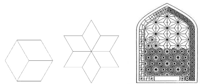
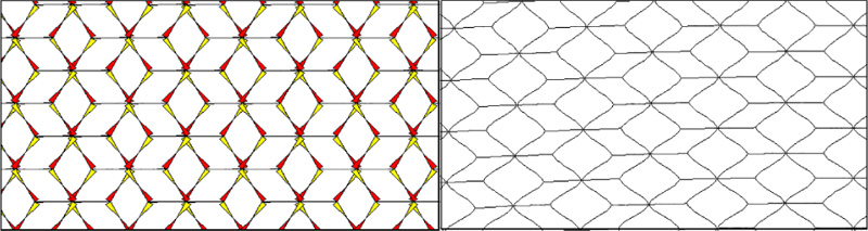
The triangular modulus (diagrid) has been the only model used in diagonal grid structures for a long time. In order to develop grid patterns, the possibility of applying other structural forms found in nature as diagonal grids has been discussed recently. The hexagon is one of the most common forms found in nature. It can also be regarded as a kind of Voronoi grid. The hexagonal pattern (hexagrid) inspired by natural (honeycomb structure) has a high-efficiency ratio (stiffness to weight). A hexagrid is a bending-dominated structure, so it is inevitably less stiff, and therefore less efficient, in terms of weight, than a diagrid [4]. On the façade of a hexagrid structure, steel density is lower (about 40%) than the density of diagrid structures. So, hexagrids will produce a better daylight performance. However, it has weaker stiffness [5]. Since hexagrid is a bending-dominated structure, it can be used in the lower parts of high-rise buildings where there is a large bending moment, transitioning to diagrid at the upper levels. This design would take into account structural and economic requirements. However, there is no specific solution for the transition zone. There has been considerable discussion and use of diagrid and hexagrid in recent designs. Although some research is dedicated to proposing other innovative patterns such as irregular Voronoi grid, pentagrid, etc., there is still a need to explore non-conventional patterns. The purpose of this study is to present a new pattern for diagonal grid structures and compare its performance with two other widely -used patterns (triangular and hexagonal). The new pattern can also be used as a solution for the transitional zone from the diagrid to hexagrid. Because this pattern's modulus is similar to the perspective view of a cube (isometric cube), it is called the isometric cube grid (IC-grid). It can also be considered as a repetition of the six-pointed star, which is an ancient Persian architectural motif (Fig. 1).
2. RESEARCH BACKGROUND
Academic research on the diagrid structural system began in 2005 by Kyoung-Sun Moon, under a doctoral dissertation from MIT University [6]. Before that, research in this field was limited to specific projects. Extensive research works have been conducted on the diagrid structural system since 2006. Research in this field can be divided simply into four categories, as follows:
1- Definitions and optimization of building components (improved dimensions of the sections, ratio of height to width of the building, angle of diagonal components, module height).
2- Analysis and design (calculation of lateral stiffness, earthquake forces, deformations, presentation of computational methods, design of nodes and connections, designing optimal dimensions of components),
3- Presenting new patterns for the diagrid system (hexagrid, pentagrid,). This study belongs to this category,
4- Review articles and case studies of implemented structures.
2.1. Research on Presenting New Patterns
Just de Meijer [7] introduced and examined the characteristics and features of the hexagrid pattern and compared the structural behavior of this pattern with the diagrid pattern in terms of stiffness and efficiency in his master's thesis from the University of Eindhoven. This structure is similar to a diagrid, except that its bracing grid is not triangular but hexagonal. In his research, he used a parametric method that could be applied to assess other types of innovative patterns as well. Mashhadi Ali and Kheyroddin [5] introduced the hexagrid pattern then compared the hexagrid and diagrid patterns in two cases with and without secondary bracing. The researchers concluded that secondary bracing increases the stiffness sensitivity of hexagrids three times more than diagrids. Taranath et al. [8] introduced the pentagrid pattern (made of irregular pentagons) as a new pattern, examined its structural properties in high-rise buildings, and compared it with the hexagrid pattern. In their study, pentagrid performed better than hexagrid against lateral deformation, and the optimal brace angle for it was 35 degrees. There is a lot written about the angle variation in diagrid structures, but very little on the variable density patterns along with building height except Montuori et al. [9] who assessed the effect of changing the angle and number of diagonals along with the building height for the diagrid pattern. Based on the results, the patterns with the tallest modules had a high requirement of a secondary bracing system for reducing the inter-story drifts and stabilizing the core gravity columns at intermediate floor levels. In addition, their design procedures can be helpful in exploring pattern solutions to develop diagrid potential. Zhao and Zhang [10] evaluated diagrid patterns with curved and varying-angle straight diagonals from bottom to top. They proposed empirical formulas for optimal values of bottom and top angles for each configuration. Montuori et al. [4] examined and compared the hexagrid pattern and its modeling and design with the diagrid pattern in a simulated high-rise building similar to the building in actual use, i.e. the 90 floor, 351 meter Sino Steel International Plaza. Researchers have proposed that the optimal angle in horizontal hexagrid and diagrid patterns is 60 degrees, while 30-50 degrees was proposed as an optimal angle in vertical hexagrid patterns. Ebin and Prakash [11] investigated the structural behavior of the hexagrid pattern in multi-story buildings with 15 stories and the aspect ratio H/B less than 7. For this application, a 65-degree angle was optimal. Saeedi Nejad et al. [12] introduced and compared the seismic performance of tubular structural systems of diagrid and hexagrid in high-rise buildings. According to the results, hexagrid had less weight than diagrid and also more resistance against progressive collapse. Lee and Kim [13] investigated a 60-story building with a hexagrid pattern and showed that the vertical hexagrid pattern is more stable than the horizontal hexagrid. Angelucci and Mollaioli [14] examined the stiffness-based methodology effectiveness proposed by literature by applying it to 90-story diagrids and showed that The stiffness-based design method could be used to determine optimality conditions only for diagrids with an inclination range of 60-70. The iterative optimization technique is suitable for steeper diagonal angles. Results show that local density is not the best approach to take. A variable pattern density is a more efficient solution by rarefying the diagonal elements from the base to the top of the building. Danish et al. [1] compared diagrid and hexagrid structures with the same loading and properties by the ETABS software, and finally, the hexagrid structure was more economical and stable than diagrid. Tomei et al. [15] investigated different geometric patterns in regular diagrid structures with new or complex shapes for high-rise buildings, in this study, possible combinations of rhombic and triangular diagonal components (cross-sections or with curved components) and their optimization in high-rise buildings are examined with a genetic algorithm to reduce the final weight of the structure when stiffness is constant. Angelucci and Mollaioli [3] examined the possibility of using non-regular grids for the structural systems of tall buildings. They focused particularly on periodic and non-periodic Voronoi tessellations. Using parametric modeling, they generated Voronoi-like patterns by gradually perturbing a regular honeycomb configuration. This paper focused on the impact of the grid arrangement on the lateral stiffness of the perimeter tube. As a result, at the same density rate, cell irregularity has no significant impact on lateral stiffness, and gradual reduction in density is a suitable strategy for tall buildings with Voronoi-like grids. Mele et al. [16] evaluated nonregular patterns based on the Voronoi diagram. This research was focused on assessing the mechanical properties of this grid based on the concept of the representative volume element (RVE) and the development of this concept on a statistical basis to account for the inherent irregularities, non-periodicity and randomness of the grid. In their work, they defined a framework that encompassed an almost endless variety of structural configurations, including diagrid, hexagrid, voronoi, foam trusses, and more. Mashhadi Ali and Kheyroddin [17] conducted studies on the seismic performance of hexagrid structures to develop their previous work. In this system, an attempt is made to reduce the concentration of damage on the converging braces to achieve a uniform drift distribution in the story and prevent forming a soft story mechanism. The results estimated the value of the proper coefficient to be 4. The optimal digonal angle was also obtained from 30 to 40 degrees. A recent review by Scaramozzino et al. [18] gives a comprehensive overview of the diagrid structural system, with a particular focus on the optimization of these systems based on geometrical patterns and recent research on diagrid nodes. The authors noted that diagrids could be further optimized based on geometrical features, making them suitable for sustainable design. Moreover, they declared grid-based tubes, including diagrids, were the top candidates for achieving efficient, attractive and sustainable tall buildings in the future.
3. RESEARCH METHODOLOGY
3.1. Introduction of a New Pattern (Isometric Cube)
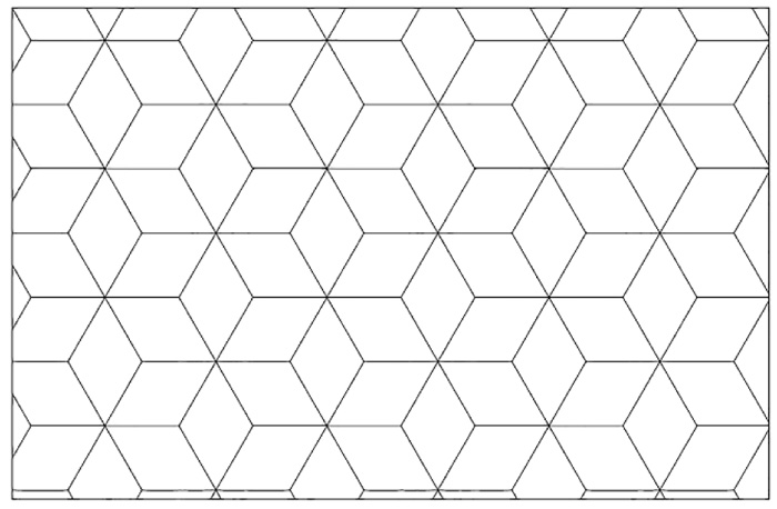
The pattern of a modular structure is created by parametric duplication of an initial motif. With duplication of geometrical shapes, a kind of tessellation emerges. Tessellation is an unlimited set of polygon duplications. These polygons fit together so that they completely cover the surface. Here, each side of a polygon is the side of the surrounding polygons. Each pattern can be created horizontally or vertically. A vertical pattern is a structure that has only diagonal or vertical elements; meanwhile, the horizontal pattern is made of only diagonal or horizontal elements. The present study focused only on horizontal patterns.
In this research, a new pattern was investigated for the diagonal grid system which was called as Isometric-Cube pattern. (IC-grid) (Fig. 2).
3.2. Investigation of Structural, Mechanical Properties of Isometric Cube Pattern
Comparisons among patterns are conducted based on efficiency. In a grid-based structure, efficiency is obtained by dividing the grid stiffness (stiffness against lateral or vertical loading) by its structural weight (here, the grid density is representative of its weight). The stiffness of a structure is a major influence on its lateral deformation. Stiffness coefficients are classified into two categories: axial and shear stiffness.
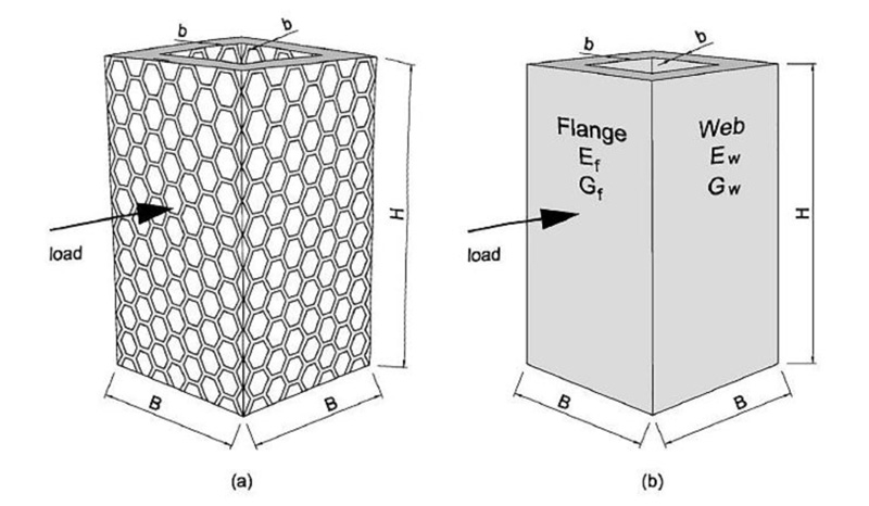
In order to analyze the grid structure, its mechanical properties are determined by comparing it to an equivalent solid structure (with similar dimensions: same width, height, and thickness). In order to determine the stiffness of the grid structure, we apply a modifying factor to the structure stiffness. A high-rise building is assumed to be a deterministic cantilever beam [4]. The beam is simultaneously subjected to bending and shear forces. Therefore, both axial and shear stiffness must be adjusted (Fig. 3).
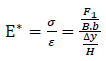
The axial moduli (E*) is defined as the ratio of the uniaxial normal stress, σ, divided by the uniaxial strain, ε, in the loaded direction in the elastic range (Equation 1). Similarly, the shear moduli (G*) is related to the shear force (Equation 2) [4].
 |
(1) |
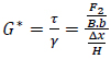 |
(2) |
Where:
F1= average normal force, which is a substitution of normal stress (σ),
F2= average shear force, which is a substitution of shear stress (τ),
B= the width of cross-section,
b = the thickness of cross-section,
H= the height of the structure (initial length),
∆x= transverse displacement resulting from shear stress when the displacements along the y-axis of nodes on the bottom and on the top edges are constrained.
∆y= shortening or lengthening resulting from normal stress,
γ = shear strain,
ε = normal strain.
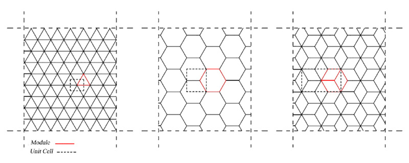
The horizontal grid (consisting of diagonal and horizontal elements) for patterns is considered here. The modulus in the hexagrid, the diagrid, and the new one are hexagonal, triangular, and isometric cube. Each of the three horizontal patterns is shown with its modulus and unit cell (Fig. 4).
3.3. Calculation of Relative Density for Different Patterns
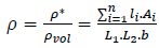
The relative density of grids (ρ) is obtained by dividing the volume occupied by solid material (ρ*) by the total volume of cell [19]. Previous research has shown that diagrid structures' efficiency is significantly related to the angle of their diagonal elements [20]. The effect of changing the angle of diagonal elements is fully considered in the concept of grid density.
The relative grid density is calculated using Equation (3):
 |
(3) |
Where the n is the total number of elements; li and Ai are the length and the section area of elements, respectively; L1 and L2 are the dimensions of unit cell along x and y direction, respectively, and b is the thickness of unit cell.
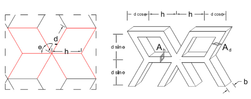
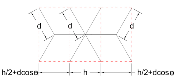
In the case of the isometric cube pattern and according to the definition of relative density, a different unit cell type is, predictably shown in Fig. (5). As we will see later, this form of the unit cell is efficient in describing the structural performance of the grid (which is a combination of two types of nodes with different numbers of connections).
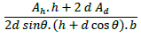
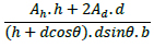
According to Equation (4), the new pattern's relative density (ρIC) is twice the relative density of the hexagrid pattern.
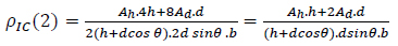 |
(4) |
Where h and d are the length of horizontal and diagonal elements, respectively, and θ is the angle between diagonal elements and horizontal axis. Ah and Ad are the area section of horizontal and diagonal elements of the grid, respectively. A comparison of the relative density of the different grids is given in Table 1.


3.4. Calculation of the stiffness correction factor
3.4.1. Determination of the representative volumetric element (RVE) for isometric cube pattern
The representative volumetric element (RVE) must first be identified to determine the structural behavior of a grid-based structure (to calculate its correction factors). The representative volumetric element is the smallest homogeneous volume unit on which the larger model's structural equations are formed, and it can be defined after determining the unit cell of each grid.
In the case of the isometric cube pattern, unlike the previous two patterns, the nodes are not of the same type in the whole grid. The first type, high-connectivity (type 1), is similar to the nodes of diagrid patterns with six connected elements; the second, low-connectivity (type 2), is similar to the nodes of hexagrid patterns with three attached elements. Therefore, the type of nodes in the new pattern is not uniform as the previous two patterns and its structural behavior cannot be described by a unique representative volumetric element with a unique node. Based on how the nodes were distinguished, it is predicted that the pattern may behave like a kind of intermediate pattern between hexagrid and diagrid. The type 1 nodes can be considered to be pin connections as in diagrid patterns, however, to achieve a uniform grid, all connections are assumed rigid in the present study, both for the six-element (type 1) and three-element (type 2) nodes.
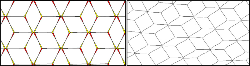
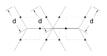
When an infinite isometric-cube grid is under uniaxial compression, if the connections are considered rigid, hinges will emerge at the elements' mid-length where the bending moments are equal to zero (Similar to the hexagrid pattern under the same conditions) (Fig. 6).
In order to simplify the structural behavior of the isometric cube pattern, it is possible to use two types of volumetric elements, one similar to the diagrid pattern (slightly modified) and the other similar to the hexagrid pattern, simultaneously in a single cell. For this purpose, to determine the load share of different volumetric elements, the unit cell is divided into three separate parts based on the position of mid-length hinges. Each part includes a volumetric element with one type of nodes (Fig. 7).
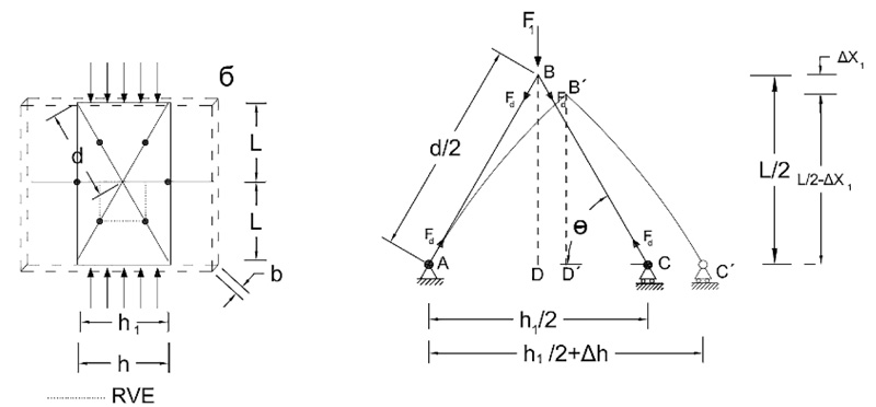
By considering the hinges' location, the size of each part can be limited to a bending frame surrounded by the inner hinges. RVE of the type 1 nodes is shown in Fig. (8) for the isometric cube pattern under uniaxial compression. This part has similarities to the RVE of the diagrid. Although there is not a third component (horizontal element) which forms a stable triangle like diagrid RVE, this frame is determinate and stable. (h1 represents the length of the base in the hypothetical triangle. According to the angles of diagonal elements, it might be different from h, which represents the length of horizontal elements in the grid)
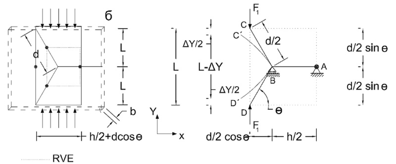
For type 2 nodes, RVE is shown in Fig. (9) under uniaxial compression. The connections are rigid in the pattern. This RVE is similar to the hexagrid’s RVE except for its dimensions. For such an RVE, deformations and modification factors have been calculated by de Meijer [7].
3.4.2. Calculation of Axial Stiffness Modification Factors of the New Pattern
By considering the effect of all forces on the elements (including axial force, bending moment force, and shear force), the values of axial stiffness modification factors for the diagrid, hexagrid and new pattern are obtained and are shown in Table 2 (For detailed calculations, see appendix A)

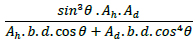


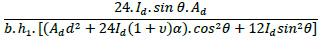


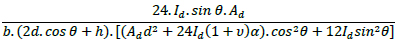
3.4.3. Calculation of Shear Stiffness Modification Factor of Patterns
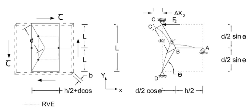
When an infinite isometric-cube grid is under shear load, if the connections are considered rigid, hinges will emerge at the elements' mid-length where the bending moments are equal to zero (Similar to the hexagrid pattern under the same conditions) (Fig. 10).
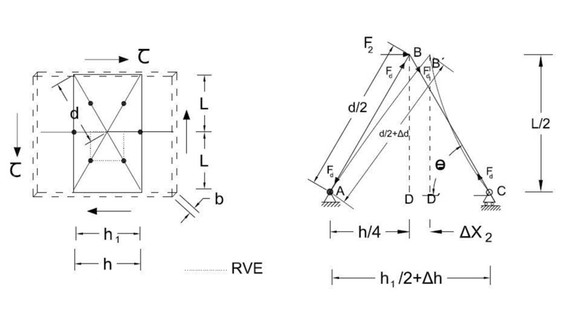
Under shear stress, RVE for type 1 nodes Fig. (11) is shown in (Fig. 11).
Fig. (12) is the RVE for type 2 nodes under shear stress. It is similar to hexagrid’s RVE whose deformations and modification factors have been calculated by De Meijer [7].
By considering the effect of all forces on the elements (including axial force, bending moment force, and shear force), the values of shear stiffness modification factors of three patterns are shown in Table Table 3. (For detailed calculations, see Appendix A)


3.5. Comparing the Modified Stiffness Ratio to Relative Density with changes in the Angle of Diagonal Elements in Different Patterns
The concept of relative density can be used to evaluate the efficiency of different grids. Dividing the grid stiffness by its relative density gives a value on which the grid's efficiency depends. This value for each grid depends entirely on the choice of the optimal angle of the diagonal elements. The optimal angle for the elements is the angle that provides the best balance between stiffness and density (in other words, it means economic expenditure) for the grid.
(Fig. 13) shows graphs that are obtained for the diagrid and hexagrid patterns based on the equations presented for axial and shear stiffness in Tables 2 and 3, and also the relative densities in Table 1. These graphs are calculated once for axial stiffness and once for shear stiffness. The obtained graphs are quite similar to those of Montouri et al. [4], which were calculated here again. By comparing the two obtained line graphs in each pattern, the range of diagonal angles where both graphs have shown the maximum efficiency is almost 50 to 70 degrees. Therefore the range of optimal angles can be considered from 50 to 70 degrees for both cases of diagrid and hexagrid patterns.
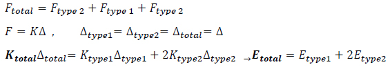
In the case of an Isometric-cube pattern with rigid connections, the stiffness of RVE must be obtained by combining the stiffness of two types of nodes (Type 1, 2). Under load, the formation of median hinges allows us to distinguish three separate structural parts which have one of two types of nodes. Each part has its RVE and is connected to the other at the median hinge of the horizontal elements (Fig. 14).
According to Fig. (14), this RVE can be regarded as a combination of two hexagrid’s RVE (with ‘Type 2’ nodes) located on either side of a diagrid’s RVE (with ‘Type 1’ node). As a solution, the stiffness of this RVE is calculated with the same formulas used to calculate spring set stiffness. In a set of parallel springs, each spring's force is different from and parallel to the other, so the total force (total) is obtained from the sum of each force. On the other hand, the change in the length of all springs (∆) under load is equal. Consequently, the spring constant of the set is equal to the sum of all the spring constants. Similarly, in axial loading, the RVE of an isometric cube is under such conditions. Therefore, similar to the sum of stiffness for parallel springs, the following Equation is used to calculate the total axial stiffness of the isometric cube’s RVE: (Equation 6)
 |
(5) |
To calculate the shear stiffness of the RVE shown in (Fig. 14), there are also some resemblances between RVE under shear load and spring set with series springs. In series springs, the force remains constant throughout the set of springs. Simultaneously, the amount of deformation of the set is equal to the sum of each spring's deformations. According to the lateral loading (shear force) applied to the entire isometric-cube grid, every RVE is under the same shear stress (similar to the springs in a series set), whereas each type of node has its share of the total force. It depends on the limited area of each node (as shown in Fig. 7). Like the series springs, the total deformation of this RVE is equal to the sum of deformation of nodes. Therefore, the equation of the total stiffness for calculating the shear stiffness of the isometric-cube’s RVE is as follows: (Equation 7)
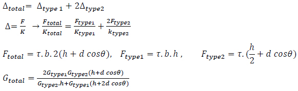 |
(6) |
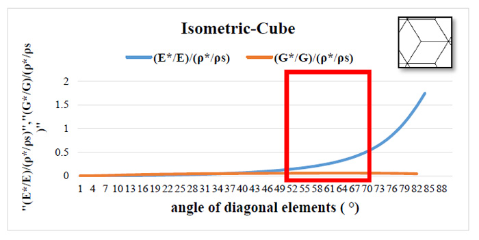
As shown in Fig. (15), the isometric cube pattern's optimal angles are in the range of 50 - 70 degrees, similar to the two other patterns.
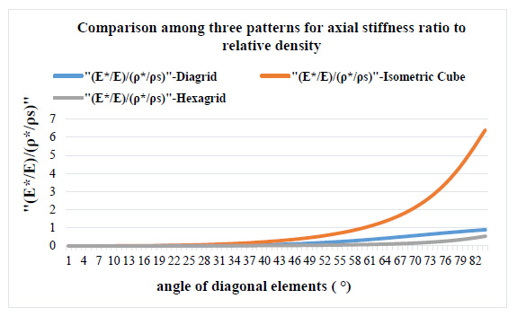
Comparison of the results from dividing the stiffness ratio to relative density for different patterns in a chart simultaneously shows that in the case of axial stiffness, the values of the graph for the isometric cube pattern with rigid connections from angles 40 to 80 degrees are significantly larger than the two previous patterns (Fig. 16).
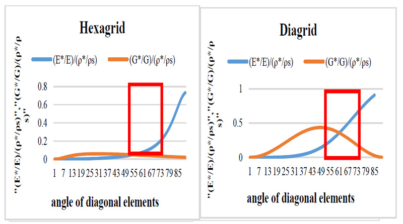
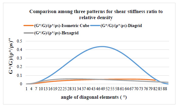
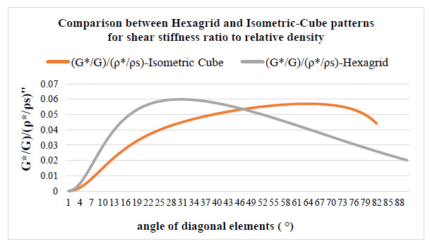
From Fig. (17), it is obvious that the efficiency of diagrid based on shear stiffness is much higher than both the hexagrid and the cubic-grid. Consequently, the diagrid pattern is the most efficient against lateral loads. According to the significant shear stiffness of the diagrid pattern, to compare between hexagrid and new patterns, the graph related to the diagrid pattern is removed. After deleting the corresponding graph, the efficiency based on shear stiffness for the new pattern compared to the hexagrid pattern is shown in Fig. (18).
Fig. (18) shows that the behavior of the isometric cube pattern is different from the hexagrid pattern in terms of efficiency based on the shear stiffness. In the case of hexagrid pattern, this efficiency declines rapidly from 30° to 88°, whereas for the new pattern, the efficiency increases substantially in the angle range 30 °- 65 °, and decreases gradually in the range 70° -80 °. Therefore, it is predicted the shear behavior of the new pattern would be better than the hexagrid pattern in the range of the most practical angles (50 - 65 degrees).
It should be noted that if the angle of the diagonal elements increases over 70 degrees in the new pattern, the diagonal elements of the type 1 node tend towards the vertical elements. Due to the proximity of four vertical elements around the type 1 nodes, it may result in implementation problems.
CONCLUSION
In order to develop the current patterns for high-rise buildings whose structural configuration is based on tubes, a new pattern for based-grid structures was introduced in this study. The new pattern is called the isometric cube (IC-grid). The main objective of this study was to assess the structural, mechanical properties of the new pattern and compare its potential efficiency with other common patterns (triangular and hexagonal).
For this purpose, the design process was performed based on a simple stiffness criterion presented in previous research (efficiency). Three patterns of diagrid, hexagrid and new pattern (isometric cube) were evaluated and compared in their horizontal position.
This pattern, unlike the two previous patterns, did not have only one type of repetitive node, so RVE of it was calculated by differentiating the two types of existing structural nodes(three-element and six-element). The results were combined to determine the stiffness of the entire grid. All connections were assumed to be rigid.
The optimal angle range of the diagonal elements of the new pattern (isometric cube) is obtained in the range of 50 - 65 degrees in the horizontal position. Isometric cube pattern and diagrid pattern have the best efficiency against axial and shear loads, respectively. In the case of efficiency based on axial stiffness, the values of the isometric cube pattern are significantly larger than the two previous patterns from angles 40 to 80 degrees. The efficiency based on shear stiffness for the Isometric cube pattern is similar to the hexagrid, but the behavior of the isometric cube pattern is different from the hexagrid pattern in the range of optimal angles. For IC-grid, the efficiency increases substantially in the angle range 30 °- 65 °, whereas for hexagrid, this efficiency descends in the same range of angles. Therefore, it is predicted the shear behavior of the new pattern might be better than the hexagrid pattern in the range of 50 - 65 degrees.
The new pattern will be suitable for transition zones from the diagrids to the hexagrids in high-rise buildings, as well as for buildings with unusual shapes and complicated architecture where shear forces are significant.
CONSENT FOR PUBLICATION
Not applicable.
AVAILABILITY OF DATA AND MATERIALS
Not applicable.
FUNDING
None.
CONFLICT OF INTEREST
The authors declare no conflict of interest, financial or otherwise.
ACKNOWLEDGEMENTS
Declared none.
APPENDIX A
A.1. List of Symbols:
F1 = vertical load
F2 = horizontal load
∆M, ∆lblending = displacement dealing with bending moments resulting from the load (F1) or (F2).
∆V, ∆Lshear = displacement deals with shear forces resulting from the load (F1) or (F2).
∆S, ∆LAXIAL = displacement deals with axial forces resulting from the load (F1) or (F2).
m1 = bending moment resulting from the unit load,
v = shear force resulting from the unit load,
u = axial force resulting from the unit load,
M = bending moment resulting from load (F1) or (F2),
V = shear force resulting from load (F1) or (F2),
S = axial force resulting from load (F1) or (F2),
∆X1 = displacement along the vertical axis (Y),
∆X2 = displacement along the horizontal axis (X)
σ1 = normal stress
τ = shear stress
ε = normal strain
γ = shear strain,
Es = modulus of elasticity in tension or compression
Gs = modulus of elasticity in shear,
Id = moment of inertia of area for diagonal elements,
Ih = moment of inertia of area for horizontal elements,
Ad = area section for diagonal elements,
Ah = area section for horizontal elements,
d = length of diagonal elements,
h = length of horizontal elements,
h1 = the length of the base in the hypothetical triangle. According to the angles of diagonal elements, it might be different from h (related to (Figs. 8 and 11)
υ = Poisson’s ratio,
α = form factor for shear,
L = Length of elements,
l = initial length (related to RVE),
b = Width (related to RVE),
0 = Angle between diagonal elements and horizontal axis.
Ax = Reaction force along with horizontal axis related to support ‘A’,
Ay = Reaction force along with vertical axis related to support ‘A’,
Cy = Reaction force along with vertical axis related to support ‘C’,
MA = bending moment related to support ‘A’,
δ = deflection,
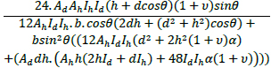
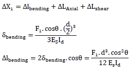
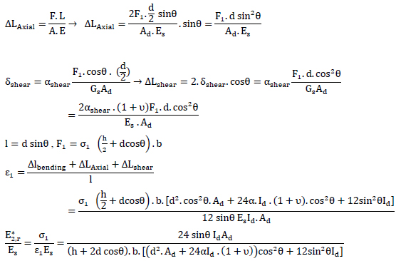
A.2. Calculation of Axial Stiffness Modification Factor for Type 1 Nodes (shown in Fig. 8)
The displacement due to vertical loading in the frame shown in Fig. (8), which is obtained by Castigliano's theorem or Unit-Load method. The vertical displacement at the point B is found to be:
 |
 |
 |
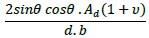
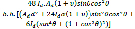
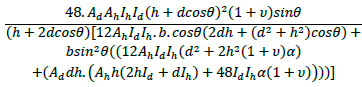
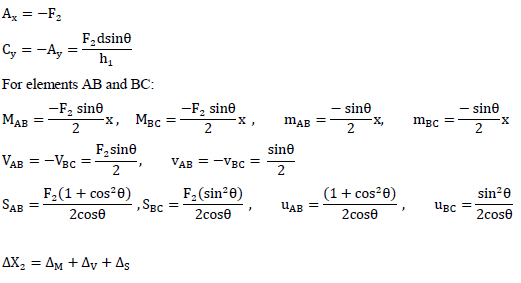
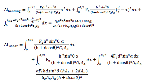
A.4. Calculation of Shear Stiffness Modification Factor for Type 1 Nodes (shown in Fig. 11)
RVE for type 1 nodes is shown in Fig. (11). The horizontal displacement at the point B is found to be:
 |
 |
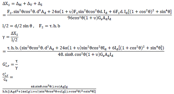 |
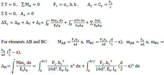
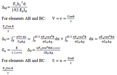
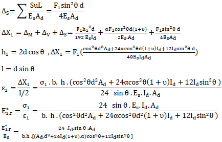
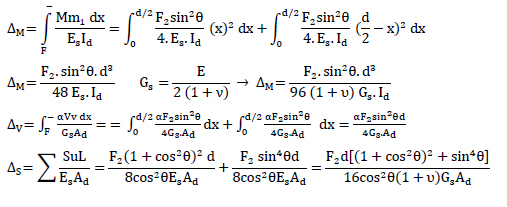
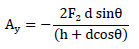
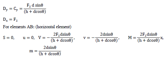
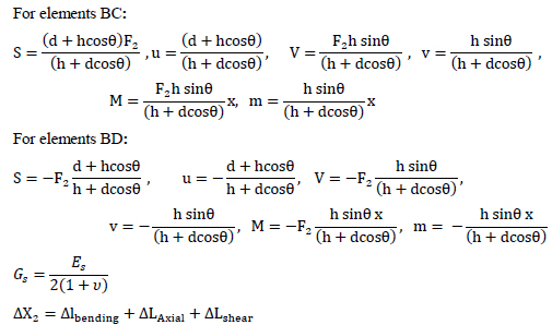
A.5. Calculation of Shear Stiffness Modification Factor for Type 2 Nodes (shown in Fig. 12)
The structure is split up into three elements: AB, BD and BC. The axial forces, shear forces and moment diagrams of all the elements should be known in order to calculate the displacements. The reaction forces are:
 |
 |
 |
 |
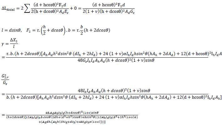 |

