All published articles of this journal are available on ScienceDirect.

Interventions to Structural System of Masonry Buildings and their Effects to their Seismic Response
Abstract
Background:
Preservation of listed buildings, depending on the importance of each one, requires the conservation of the whole structure or of only the external walls, often called shell of the building, or even only of the façade. In the latter cases, although the new structure is studied to undergo the applied loads according to the codes in force, less research is made to study the response of the remaining structure under seismic loads.
Objective:
The response of unreinforced masonry (URM) structures with alterations of the original load bearing system to strong ground motions is studied in the present paper. Commonly used radical interventions comprise the addition of a steel or reinforced concrete frame in the interior of the structure after removal of interior load bearing or/and dividing walls. The embedded substructure is designed to support the functional loads of the building and commensurate seismic design forces associated with its mass. In this setting, perimeter walls are relieved of any bearing action apart from resisting the state of stress associated with their self-weight. An important design decision is the extent of contact and interaction that is allowed to occur between the perimeter URM walls and the interior structural system; both options present advantages and disadvantages.
Methods:
The effect that this design option has on the seismic response of the composite system is studied in this paper using linear elastic finite element analysis. The effect of each intervention is estimated by comparing the principal tensile stresses (pts) developed on the walls before and after each intervention as well as the percentage of the wall areas in elevation where the pts are higher than tensile strength of masonry.
Results:
It is found that connection of the frame to the masonry walls at several points around the floor and roof perimeters creates a diaphragm action that effectively reduces the out-of-plane bending of the self-standing perimeter URM walls without excessive local stress intensities and increases the shear strength of the building. Lack of contact between the old and new load bearing elements leads to higher intensity stresses due to bending and only the addition of a reinforced concrete tie belt at the top of the walls may mitigate serious damage.
Conclusions:
The cooperation of the Moment Resisting Frames, irrespective of the material of the frame (reinforced concrete or structural steel) and the walls by connecting the perimeter structural walls with it at floor and roof levels, is more efficient to the stress state of the walls transforming the critical out-of-plane bending of later to shear one, preventing them from out-of-plane collapse.
1. INTRODUCTION
In former years, structural interventions in load bearing masonry buildings were primarily aimed at maintaining the existing structural system through repair. With the introduction of preservation requirements (e.g. [1-5]) any change of building function requires not only the reorganization of spaces, but also strengthening and rehabilitation of the building system so that it complies with the requirements of current seismic codes. In recent years, the lack of specific requirements for masonry rehabilitation and the familiarity of engineers with concrete and steel led to a state of practice whereby interventions in heritage buildings which were classified for preservation (Listed Buildings according to Historic England [6]), were dealt with using a dual load bearing system. In the United Kingdom, it is common practice, even when dealing with Listed Buildings the protection of only the façade of the building as shown in Fig. (1a) which functions as a part of a scenography. In other countries, the exterior walls nevertheless are façades or not are preserved through repair, repointing and occasional strengthening with internal shotcrete jackets, whereas the structural function is assigned to an added reinforced concrete or steel frame fitted in the interior space. Actually, the facility of steel construction has led to a prevalence of this system over reinforced concrete in such applications; an added reason is that the construction of composite floors does not require a dense arrangement of load bearing elements so that the steel moment-resisting frame is more economical and its foundation easier.
In interventions of this type, usually the objectives of design and assessment pertain to the added frame, whereas the surrounding masonry shell is repaired or strengthened with the addition of a lightly reinforced concrete jacket, usually sprayed. An issue of concern in cases such as this is the seismic response of the remaining perimeter masonry shell with regards to: a) What is the most pertinent type of frame to be fitted so that it does not collide with the perimeter structure in case of dynamic excitation, and b) whether the new structure ought to be integrated (interacting) with the perimeter walls of the existing building in order to secure an improved composite action, or alternatively ensure that the two systems are completely isolated from each other. Numerous studies are based on recent researches on both masonry structures or the masonry as structural material of new or old and historic structures. The research concerns the seismic behavior of masonry buildings as e.g in [7] and [8], the modelling and linear or non-linear analysis as in [9-13]. A considerable part of the relevant research is pointed out to the strengthening of both only the masonry and the whole structure as in [14-18]. Another field of research concerns the materials used for strengthening, their effectiveness, strength, compatibility with masonry [19-22] and fitting to various load bearing masonry types, as e.g in [23-25]. In [26] the construction details of a horizontal diaphragm with moment resisting steel frame and wooden floor are given. The authors did not find articles on the cooperation of the existing perimeter walls with a new frame structure erected inside an old masonry building to carry the live and seismic loads applied as a result of extensive rehabilitation. The type of the frame, namely heavy and stiff vs flexible and deformable as well as the connection or not of the frame structure to the existing remaining walls have not yet been investigated. The codes in force in Europe [1], as well as in USA [2-4] do not refer any requirements about this critical issue.
From the above mentioned, it is clear that there is a gap in the research regarding the type of the frame as well as the interaction of the addition of a frame structure to bear the live loads of a new usage and the remaining preserved perimeter walls. It is the objective of this paper to address these issues.
Particularly in this study, fitting of a moment-resisting frame in the interior of an existing building is explored with reference to the choice of frame material as it relates to robustness, stiffness and compatibility with the preserved perimeter wall system. Two choices are considered: a) construction of a reinforced concrete frame that also supports reinforced concrete slabs for gravity and service load bearing and b) construction of a steel frame that supports composite steel-concrete plates. Furthermore, alternative modes of interaction of these frames with the remaining perimeter walls of the existing building are investigated. So, the four cases examined in this study are the construction of:i) an internal reinforced concrete frame with contact with the masonry shell, ii) a steel frame inside the masonry shell in contact with the masonry shell, iii) a frame (of steel or of reinforced concrete) with no contact with the masonry shell, iv) fitted frame with no contact with the masonry shell along with the construction of a reinforced concrete tie beam at the crest of the remaining masonry walls. For this purpose, an actual, fully documented building (with detailed records of damage patterns and material properties), which had undergone extensive seismic damage is analyzed subjected to the seismic forces specified by Type I earthquake spectrum of EN1988-1:2004 [27]. The choice of this building was based on the need to assess the hypotheses made on both the simulation of the structure and the materials as well by comparing the predictions of the analysis with the actual developed damage so as to procced to investigate the above mentioned interventions. The investigation is conducted using linear elastic finite element spatial analysis of the structure which is explained in more detail in the next paragraphs. The effect of each intervention is estimated by comparing the principal tensile stresses (pts) developed on the walls before and after each intervention as well as the percentage of the wall areas in elevation where the pts are higher than tensile strength of masonry.
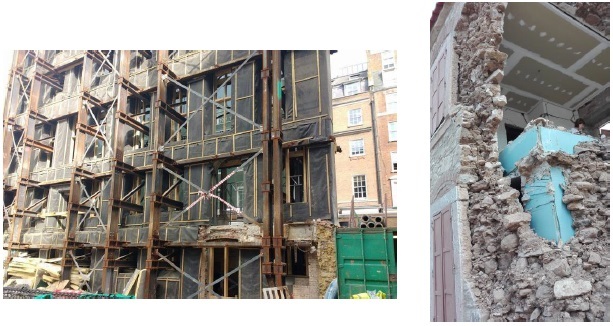
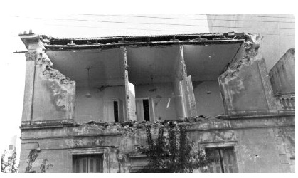
It is worth mentioning that sometimes the results of improper alterations are obvious only after a strong earthquake, as shown in Fig. (1b) where an internal 1-storey reinforced concrete frame is fitted in the interior of a 2-storey stone masonry house. The Figure shows the total collapse of the masonry after the Lesvos Earthquake of Ms=6,3 which was recorded nearby [28].
2. ASSUMPTIONS FOR THE LOADS AND THE MODELLING
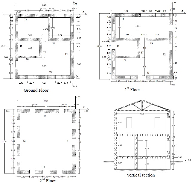
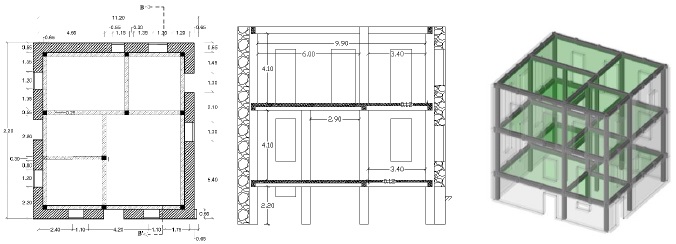
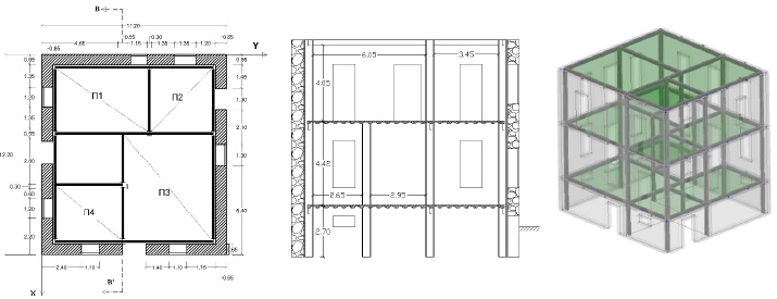
An existing building with severe seismic damage is chosen as the reference building for the study. The main reason for this selection is to verify the provisions of both the assumptions and the mathematical model, with the developed damage due to an earthquake which is in fact a 1:1 shaking table test. The two-storey with basement building is of uncoursed stone masonry with timber floors and roof. The mortar of the joints is a poor-quality lime mortar. As shown in Fig. (2), the basement and the first storey have additional internal load bearing walls to support the floors whereas the upper second floor has only perimeter external load bearing walls which are needed to support the timber roof.
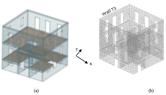
In the following sections, details concerning each one of the strengthening schedules are presented. In this section, only the common assumptions to all cases are pointed out. To model the load bearing walls of the structure and the added slabs, a three-dimensional finite element model was developed using isoparametric thick Mindlin-plate finite elements [29]. Any timber components of the initial building (e.g timber joists) and the frame members of the fitted moment resistant frame are modeled using linear beam elements, as shown in Fig. (3). The load from the roof is considered to be applied at the crest of the relevant perimeter walls. In the absence of any visible distress in the ground or any signs of differential settlements, a con-compliant foundation was assumed for the base of the model.
The mechanical properties of the materials were taken as follows:
- For the stone masonry walls: compressive strength fwc=1.7 MPa, tensile strength fwt=0.1*fwc=0.17MPa, modulus of elasticity Ew=1200*fwc=2.05 GPa, and specific weight γw=21kN/m3.
- For the reinforced concrete: modulus of elasticity Ec=27.5GPa, and specific weight γc= 15kN/m3.
- For structural steel: modulus of elasticity Es=210GPa, and specific weight γs=78.5kN/m3.
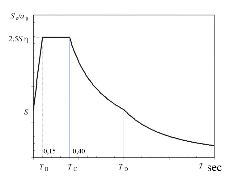
The seismic loads were obtained from the response spectrum Type I of EN1988-1:2004, based on zone II of the seismicity map of Greece (seismic coefficient or design Peak Ground Acceleration, PGA, ag=0.24) (Fig 4).
From the eigenmode spectral analysis the fundamental periods of the building for translation along the x and the y axes before any intervention were calculated 0.20 sec and 0.24 sec, respectively, so that the total acceleration demand lies in the plateau of the design response spectrum (constant acceleration range). For usual importance and soil requirements (S=1) from the elastic spectrum (behavior coefficient q=1) the value of the elastic spectral acceleration was estimated from the Eq (1) to be Sa(T)=0.6m/sec2. It is noteworthy to say that for damping ratio 20%, which is reasonable for the URM, the spectral acceleration of the ground motion from the Eq. (1) is 0.42m/sec2, which was recorded in the vicinity of the building location during Kalamata, Greece Earthquake [30]. The analyses were conducted for load combinations G+0.3Q±Ex±0.3Ey and G+0.3Q±0.3Ex±Ey (basic combinations along the x and y directions), as illustrated in Table 1.
| Load Case No | Load Combination |
|---|---|
| 1 | G+0.3Q+Ex+0.3Ey |
| 2 | G+0.3Q+Ex-0.3Ey |
| 3 | G+0.3Q-Ex+0.3Ey |
| 4 | G+0.3Q-Ex-0.3Ey |
| 5 | G+0.3Q+0.3Ex+Ey |
| 6 | G+0.3Q-0.3Ex+Ey |
| 7 | G+0.3Q+0.3Ex-Ey |
| 8 | G+0.3Q-0.3Ex-Ey |
 |
(1) |
where:
ag=0,24g the ground acceleration on rocky soil,
η is the damping correction factor with a reference value of  for ξ=5% viscous damping, ξ expressed as a percentage.
S=1,00 for soil of type A for which TB = 0,15sec and TC=0,40sec
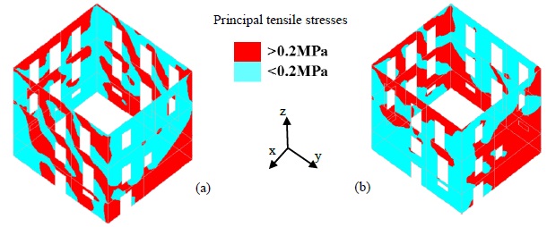
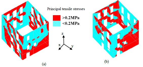
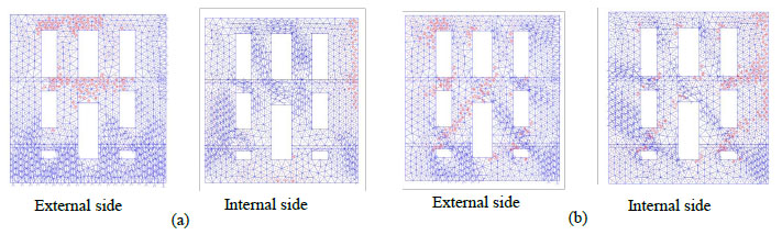
In general, results from this type of analysis are presented either in the form of equal-stress contours, or in the form of the flow of principal stress vectors; the latter mode of presentation is chosen in order to illustrate the flow of forces through the structure to the foundation. The multicolored contours provide information regarding the intensity of the anticipated damage whereas vector representation of the stress resultants provides information about localization and predicts orientation of cracks [31]. The stresses plotted may occur either in the interior or the exterior facades of the considered walls. In this paper, as failure criterion of URM is chosen as the criterion of principal tensile stress; the regions of the walls where, for the specific seismic load combination, the principal tensile stresses (pts) in the respective wall façade exceed the tensile strength of the masonry, are illustrated in red (dark in black-white printing) color and identify regions where cracking is anticipated. The blue (light) regions are those where the pts are lower than the tensile strength of masonry.
Tables 2-5 present for each scenario examined and for all seismic load combinations as outlined in Table 1, the ratio of the peak tensile principal stress, maxσ1, divided by the value of the same variable in the original state of the building. Although in each case the actual structure and the associated mathematical model are different, stress redistribution being the natural consequence in case of discord between actual structure and its model, the tables provide an overall picture consistent with the analytical results and the systematic observation of patterns for each of the 64 cases for each intervention scenario (4 walls x 2 facades x 8 load combinations).
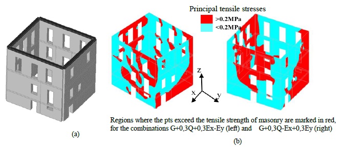
3. ORIGINAL BUILDING
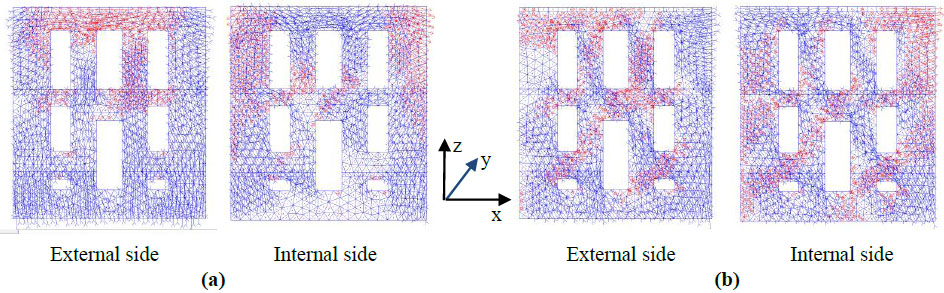
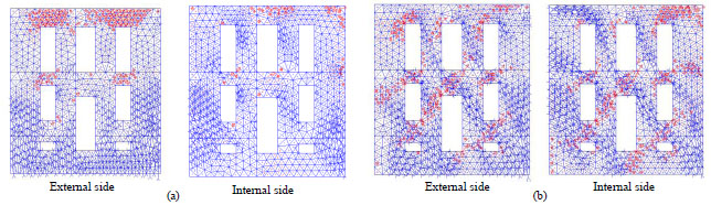
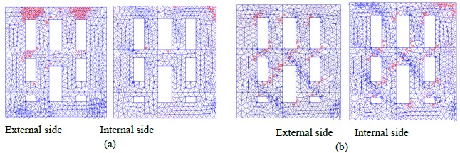
The plan of the original building is depicted in Fig. (2). In Fig. (3a), the 3D model and in Fig. (3b), both the finite element discretization of load bearing walls and the beam members modeled of the timber joists are shown. In this section, results from the analysis of the building model in its original state are conducted. From the analyses, it was found that regardless of load combination, a fraction amounting to 40% of the masonry walls developed tensile stresses which exceeded the tensile strength of masonry with a peak value of over 1.5 MPa. This result follows from the investigation of the state of stress on the interior and exterior facades for all eight combinations considered (16 cases for each wall). Fig. (5a) presents as an example, in red color, the areas of the external facades of the walls where the pts exceed the value of the tensile strength of masonry, namely 0.2MPa, for the seismic combination of G+0.3Q+0.3Ex-Ey and in Fig. (5b) for the combination of G+0.3Q+Ex-0.3Ey; light blue areas in the figures represent the areas where the pts are lower than the tensile strength of masonry. The trajectories of the principal stresses on the external and internal sides of the wall T3 shown in Fig. (6), are plotted in Fig. (7) identifying the orientation and direction of principal flexural moments bending the perimeter walls in out-of-plane action Fig. (7a), in which the free-standing wall system is the most susceptible as well as in-plane action (Fig. 7b). From these figures, it becomes obvious that in the case of walls that are oriented parallel to the main component of excitation (identified by the seismic loading which is factored by 1.0 in the combinations of Table 1, the trajectories of principal moments are inclined with respect to the horizontal defining diagonal struts that flow between openings towards the foundation see Fig. (7b). These trajectories correspond to the regions of diagonal cracking (which becomes bi-diagonal upon load reversal). If the main component of the seismic combination is transverse to the wall, the horizontal direction of the pts corresponds to the vertical cracking at the top of the walls as well as near the corners; this cracking may turn to partial collapse of the wall. This out-of-plane effect affects mainly the upper floors acting as a cause of damage in that region and it is entirely compatible with the damage shown in Figs. (5 and 6) it is also surmised that the pts exceeds the tensile strength of masonry at the wall intersections, particularly at the upper level, where wall separation at the corners was reported. If the analysis results are obtained in vector form, as shown in Fig. (7), then it is evident that the analytical findings entirely match the observed damages that were reported during the Kalamata earthquake of 1985 [31]. As an example, consider here the visual damage of wall T3 illustrated in Fig. (6) when compared with the stress calculated for the external side (façade) of the wall shown in Fig. (7a).
4. ADDITION OF AN INTERNAL REINFORCED CONCRETE FRAME
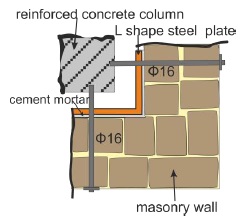
It is common when dealing with the rehabilitation of preserved buildings, to demolish all internal load bearing walls or even all walls except the façade as in Fig. (1a) and to construct a reinforced concrete or steel frame so that the preserved walls hide the modern construction behind. In this section, the construction of reinforced concrete frame will be studied. Implementation of this intervention requires removal of all the interior walls as well as the floors and the roof whereby a moment-resisting reinforced concrete frame is fitted in the interior of the structure and supports the slabs also made of reinforced concrete. During implementation, the new structure can either be in contact and connected with the load bearing walls through L-shaped steel sections or, alternatively, it may be entirely separated from the masonry shell. In both cases, this intervention may potentially present problems in the foundation because even in the commonest case where the foundation of the existing walls comprises a slightly thicker wall (an increase of wall thickness by about 0.1 m on each side), it is clear that the construction of the columns and particularly the foundation of the perimeter ones requires destructive intervention of the wall’s foundation. Furthermore, considering the geometric constraints on the perimeter of the addition, it follows that all the footings of any perimeter columns should be eccentric. In practice, sometimes beams and columns are integrated in channel-like openings which are created by the removal of the masonry units. This common practice is potentially dangerous and should be avoided because for the masonry these channels may have dimensions large enough that they cause a significant reduction of the wall thickness, so that the horizontal channels cause eccentric application of the loads, whereas the vertical ones subdivide the walls in vertical cantilevers. A dramatic failure most likely owing to this practice has been reported in North Eastern Greece during rehabilitation of a monumental former industrial masonry building, which collapsed due to dynamic excitation during excavation works causing the death of the workers implementing the procedure.
Herein, for the intervention in the building considered the columns of the fitted frame were assumed to have dimensions of 300mm x 300mm and the beam sections were taken as 250mm x 400mm. Fig. (8) presents the layout of the frame members in the ground storey plan, a vertical section and a 3D model representation of the intervention. Modelling of the new structure was based on the use of linear frame elements. Two cases were considered; one where the fitted frame has a clearance from the surrounding walls, and one where the two systems are in contact. To model the last case, fictitious short frame members spaced on the interior surface of the free-standing wall at a square grid of 2.0 m, having steel properties, were used to model connections between the load bearing walls with the frame at the floor levels as shown in Fig. (9) which is a detail of the corner connection of this frame to the existing perimeter walls. In the case where no interaction exists between walls and the frame, the building was analyzed empty with only the perimeter walls. The latter is examined below as a separate example in Section 6 under the title “Construction of a fitted frame with no contact with the masonry walls”.
When the reinforced concrete frame was connected in the manner described above, it was found that the magnitude of the pts in the masonry walls is practically equal to that of the original building, although the flexural behavior of the walls was converted to shear-controlled behavior. Fig. (10) presents for comparison the pts values for the respective loading cases of Fig. (5) and Table 2 gives the ratios of the peak principal stresses in each wall, regardless of the façade in which they develop (internal or external) after the fitting of the reinforced concrete frame. Values are normalized to their respective counterparts obtained from analysis of the original building. The pts values owing to flexure of the walls are reduced at the expense of increased shear values so that in the end no significant change in principal values may be remarked. As illustrated in Table 2, the average value of the peak principal stress ratio after the intervention to those of the original building is near 1.0. Comparing this intervention and the original building, it was also found that the regions of the walls where pts exceed the tensile strength of the masonry have almost equal size.
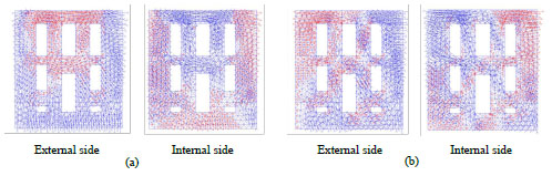
The reduction of the flexural stresses is interpreted upon the observation that slaving of the walls by the frame at the floor levels (which is effected by the connectors) enables a diaphragm-like action thereby reducing the out-of-plane wall displacements particularly in walls fixed vertically between successive diaphragms. The increase in the pts values owing to shear action is explained since the seismic force is transferred mainly by the original perimeter walls which are now mobilized in composite action with the fitted frame; in Fig. (11) note the trajectories of the diagonal force paths in the walls that are parallel to the main earthquake component. Furthermore, the reduction of the vertical (compressive) loads owing to roof and flooring, is carried from the new frame, causing an additional increase of tensile stresses. Fig. (10) presents the areas of the external surfaces of the walls where the pts are higher than the tensile strength of the masonry and may compare with the relative Fig. (5) concerning the original building. In Fig. (11) the pts of both the external and internal faces of walls are presented by their trajectories and may compare with the ones of Fig. (7). As it is seen, the pts at the corners are eliminated and no separation of orthogonal walls is predicted.
| Load Case Combination | |||||||||
|---|---|---|---|---|---|---|---|---|---|
| Wall | 1 | 2 | 3 | 4 | 5 | 6 | 7 | 8 | |
| T1 | 0.86 | 1.17 | 0.88 | 1.23 | 1.00 | 0.80 | 1.19 | 0.98 | |
| T2 | 0.82 | 0.74 | 0.90 | 1.19 | 0.93 | 1.10 | 0.84 | 1.06 | |
| T3 | 1.14 | 0.81 | 1.24 | 0.86 | 1.16 | 1.31 | 0.88 | 1.00 | |
| T4 | 1.08 | 1.49 | 0.81 | 0.75 | 0.97 | 0.92 | 0.97 | 0.87 | |
5. FITTING OF A STEEL FRAME INSIDE THE MASONRY SHELL
This section investigates the response of the building if a moment-resisting frame is fitted inside the masonry shell comprising structural steel elements and supporting composite slabs. As in the case of a fitted reinforced concrete frame discussed in the preceding, for implementation of this solution, it is necessary to remove all the interior load bearing walls of the building. Foundation of the new components is easier in this case owing to the lower weight of the steel frame as compared to the conventional concrete frame, and it does not require extensive intervention into the existing foundation. Using pertinent dimensioning and detailing for the design service and earthquake loads, it was determined that columns were HPE 300 cross sections, whereas the corresponding beam sections were IPE 270, having a plan arrangement as illustrated in Fig. (12). The frame was assumed to be attached to the perimeter walls of the building, a detail that is much easier to implement as compared to the case examined previously and shown in for the construction of concrete frame. The option of complete detachment between the two structural systems (steel frame and masonry shell) was also considered and examined in Section 6 Construction of fitted frame with no contact with the masonry shell.
From detailed examination of the results, it is evident that the two fitted systems are equally effective in terms of improvement of the structural response. At this point, it is relevant to note that in both cases, the fitted frames had a clearance from the masonry shell and they were attached only at the levels of the diaphragms with the help of steel angles, so that effectively what is studied is the influence of the partial diaphragm action that can be secured by the two alternative types of fitted frames. It is shown that the responses are practically identical, not just qualitatively but quantitatively as well, as illustrated from the values of Table 3. Thus, the distribution of the pts in the case of construction of a steel fitted frame is identical to that obtained when constructing a concrete frame provided that the added members are not in contact with the existing walls but are attached at discrete points at uniform spacing (here the distance was taken equal to 2.0 m at the floor levels). This is also seen when comparing Figs. (5 and 13). By comparing Figs. (11 and 14) where the trajectories of pts are drown, it is concluded that in case of steel frame the principal tensile stresses are smaller but still exceed the tensile strength of masonry.
| Load Case Combination | |||||||||
|---|---|---|---|---|---|---|---|---|---|
| Wall | 1 | 2 | 3 | 4 | 5 | 6 | 7 | 8 | |
| T1 | 0.98 | 1.12 | 1.00 | 1.17 | 0.89 | 0.95 | 1.29 | 1.15 | |
| T2 | 0.87 | 0.75 | 0.72 | 1.16 | 0.92 | 1.13 | 0.88 | 1.16 | |
| T3 | 1.02 | 0.78 | 1.21 | 0.82 | 0.82 | 1.03 | 0.96 | 0.90 | |
| T4 | 0.91 | 1.43 | 1.01 | 0.87 | 0.79 | 0.97 | 0.96 | 0.91 | |
6. CONSTRUCTION OF FITTED FRAME WITH NO CONTACT WITH THE MASONRY SHELL
This section examines the behavior of the building in the case where the fitted frame, (concrete or steel) is not in contact with the perimeter walls which, in this case, only carry their self-weight. In investigating the buildings’ performance, the model comprises only the self-standing perimeter walls. When an unattached frame is fitted in the interior the walls typically have large spans height-wise and lengthwise (high slenderness) and, bearing no other loads except their own weight, they have a reduced shear and flexural strength [32], a fact that renders them particularly vulnerable. For the structure under investigation, the walls are 10m high and the spans are 12.2m and 11.2 m in the x and y directions respectively. After this intervention, the state of stress is expected to be more severe than in all other cases: the unloaded four perimeter walls, without the favorable effects of compression due to overburden loads and with no contribution of diaphragm action and transverse support, will be subjected to intense out-of-plane flexure both in the length-wise as well as along their height. To improve this behavior it is pertinent to construct a perimeter or ring beam of reinforced concrete at roof level, also called a tie-beam. This intervention is rather easy to implement and has minor cost, whereas it is expected to impact the building behavior favorably in moderating the state of stress in the upper floor, particularly at the corners, as it encourages framing action between orthogonal walls [33]. In the following, the paper presents analysis results of two alternatives in the case where a fitted frame is constructed without attachment to the perimeter walls of the building; case (a), the walls have no ring beams at the roof level, whereas in case (b), a ring beam has been properly added as part of the retrofit.
6.1. Walls without a Ring Beam
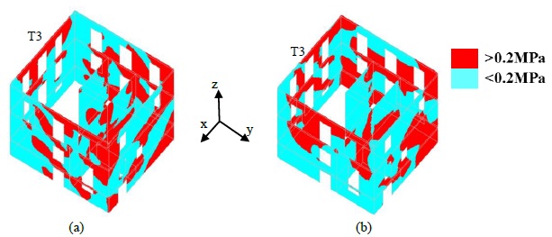
From the analysis results, the data of Table 4 and Fig. (15) the anticipated unfavorable seismic performance of the building is confirmed. In relation with the original structure, whose calculated seismic performance was discussed in detail and is shown in Fig. (5), an increase in the values of pts in excess of 20% is observed here (the mean of values listed in Table 4 is 1.27), whereas the wall areas where the pts exceed the tensile strength of masonry are increased approximately by 50%. Fig. (16) illustrates that walls orthogonal to the primary action of the earthquake are severely distressed in the upper floor, particularly at the corners. Note the absence of the diagonal strut formations that characterized the participation of the perimeter walls in resisting shear; here the behavior is dominated by out-of-plane bending action.
6.2. Construction of a Ring Beam at Roof Level
In the previous section, the calculated seismic response of the building when retrofitted with a fitted frame without attachment with the remaining perimeter walls was examined, without any further intervention to improve the structural integrity of the walls and their cooperation on the absence of any diaphragm function. As this type of retrofit was shown to be particularly unfavorable for the already vulnerable walls, herein the influence of the addition of a reinforced concrete ring beam at the perimeter of the building at roof level was examined as is seen in Fig. (17) (a). The intention here is to secure framing action between orthogonal walls at the most vulnerable location, i.e. at the corners of the upper level of the structure, a measure that is particularly popular due to the ease of implementation and low cost. The effectiveness of a similar retrofit solution by constructing a tie beam at the crest of each floor has been investigated [34, 35] and it was found that it may effectively lower the pts by as much as 30% regardless of the direction of the seismic action, and by 50% in the most vulnerable walls of the upper floor, for the critical seismic direction orthogonally to the walls. Typical dimensions as used in practice for the ring beam are considered: the ring beam cross section is taken as 300 mm high having a width equal to the thickness of the masonry wall. It is also assumed that the ring beam is reinforced with the minimum reinforcement amounts as specified by current codes. Note that occasionally, the ring beams are unreinforced in field application, which defeats the purpose of its placement as the tensile stresses will necessarily exceed the low tensile strength of plain concrete. To function as intended, i.e. in order to promote framing action, the tie beam must be reinforced so as to exhibit a fundamentally ductile behavior. Longitudinal reinforcement is distributed around the beam perimeter in amounts of 4Φ12 having closed stirrups placed at Φ10/20.
| Load Case Combination | ||||||||
|---|---|---|---|---|---|---|---|---|
| Wall | 1 | 2 | 3 | 4 | 5 | 6 | 7 | 8 |
| T1 | 1.23 | 1.44 | 1.21 | 1.43 | 1.17 | 1.14 | 1.21 | 1.26 |
| T2 | 1.30 | 1.34 | 0.98 | 1.03 | 1.09 | 1.38 | 1.11 | 1.22 |
| T3 | 1.76 | 1.20 | 1.83 | 1.28 | 1.13 | 1.11 | 1.33 | 1.37 |
| T4 | 1.13 | 1.30 | 1.47 | 1.60 | 1.15 | 1.17 | 1.14 | 1.14 |
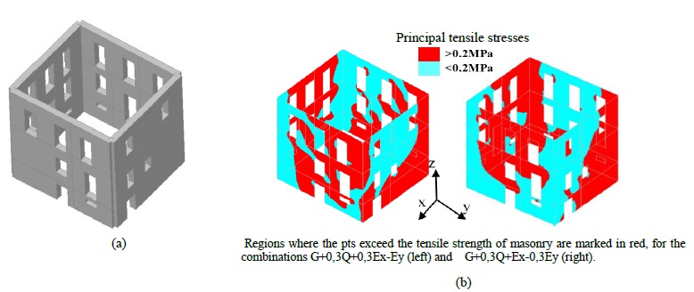
As illustrated in Table 5 and Figs. (18a and b), addition of the ring beam affected a reduction by 40% in the values of the pts in the perimeter walls and by 15% approximately in those areas of the wall surfaces where the pts exceeded the tensile strength of masonry, as compared to the respective values of the building model examined in the preceding paragraph, namely without tie beams. Comparing this case with the one with a partially connected fitted frame, it is concluded that the state of stress is similar, although the partially connected fitted frame is more effective in engaging the perimeter walls to in-plane shear action in lateral load resistance. This aspect of response, to the extent that is marked by the field of diagonal struts in walls parallel to the main direction of action indicates a much more moderate participation in the case where walls, although unconnected to the fitted frame, are nevertheless tied at the crest with a ring beam. In comparison with the initial building, although the regions where the pts exceed the tensile strength of masonry are spread over a greater portion of the walls surfaces (Fig. 17b), their magnitudes are reduced by 17% on average, as illustrated in Table 5 and in Fig. (19e). Thus, it is concluded that best performance with fitted frames when the dual systems are unconnected is when a hybrid approach is followed, namely when each loadbearing system is strengthened through framing action to perform under earthquake load. This is achieved by removing any interior existing walls to facilitate fitting of a full moment resisting frame that carries service load and corresponding mobilized inertia forces in the event of an earthquake. At the same time, the remaining perimeter walls after the necessary repairs through e.g. repointing, are connected at the roof level through construction of a tie or ring beam intended to enable framing action of the wall system, separately from the fitted structure.
| Load Case Combination | ||||||||
|---|---|---|---|---|---|---|---|---|
| Wall | 1 | 2 | 3 | 4 | 5 | 6 | 7 | 8 |
| T1 | 0.61 | 0.94 | 0.69 | 0.80 | 0.73 | 0.67 | 0.76 | 0.67 |
| T2 | 0.69 | 0.61 | 0.75 | 0.76 | 0.82 | 1.14 | 0.71 | 0.83 |
| T3 | 1.28 | 0.82 | 1.34 | 0.82 | 0.80 | 1.03 | 0.73 | 0.69 |
| T4 | 0.78 | 1.02 | 0.76 | 0.84 | 0.97 | 0.87 | 0.91 | 0.81 |
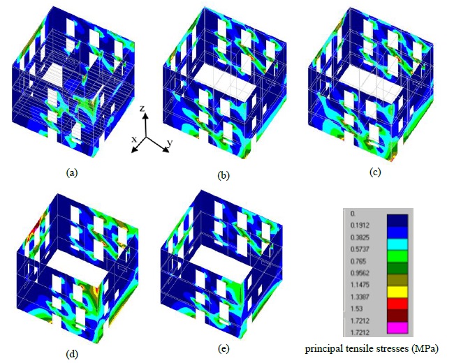
7. COMPARISON OF THE EXAMINED CASES
For the results of this study to be clearer, in this section, a direct comparison of all the alternatives examined is presented. The results are shown in Fig. (19) in the form of contours of principal tensile stresses for one of the eight seismic combinations examined, the seismic load combination G+0,3Q-0,3Ex-Ey. As it is shown in the color pallet, the dark blue color represents areas of the walls where pts are less than the tensile strength of masonry.
CONCLUSION
This paper explored the implications of an invasive retrofit procedure used throughout southern Europe for rehabilitation of old unreinforced masonry structures and to upgrade the level of earthquake protection they provide to acceptable levels, so that they may continue operation as functional spaces. The essential ingredients of the procedure is to create a dual structural system that comprises a perimeter unreinforced masonry shell of the exterior facades of the original building, and a fitted Moment Resisting Frame (MRF) that carries the functional loads of the building. Two options are considered for the type of MRF, a) reinforced concrete frame with concrete slabs for the floor and the roof, and b) structural steel for the frame with composite floors. In addition, for each type MRF two options for the degree of connection with the perimeter walls to enable composite action where examined, a) connection with the perimeter walls to ensure diaphragmatic service and b) lack of connection to the free-standing perimeter walls. As the last option proved to increase the vulnerability of the walls, the last examined case is the additional strengthening of the latter with the addition of a tie beam at roof level to enable frame-action between perpendicular facades.
The investigation took place through linear elastic FE analysis of an existing URM building damaged by an earthquake, considering eight seismic combinations and the efficacy of each option was gauged based on the extent and intensity of the tensions stress fields in the preserved perimeter walls. The results are based on the stress state of both the external and internal side of the walls. Two criteria was considered, a) the value of the ratio of principal tensile stresses after the intervention to those before it and b) the area of the wall in elevation were the principal tensile stresses are greater than the tensile strength of masonry.
It was found that the type of the MRF is not of significant importance. The most significant finding is the interaction of the two systems by provided or not connection of frame to walls. The cooperation of the MRF and the perimeter structural walls by connecting them at floor and roof levels is more efficient to the stress state of the walls transforming the critical out of plane bending of later to shear one, prevented them from out of plane collapse. The pts values owing to flexure of the walls are reduced at the expense of increased shear values so that in the end no significant change in principal values may be remarked., the average value of the peak principal stress ratio after the intervention to those of the original structure is near 1.0; it was also found that the regions of the walls where pts exceed the tensile strength of the masonry have almost equal size compared to the original building.
The construction of a ring beam is a very effective way to reduce out of plane tension and the implications of high slenderness in the perimeter shell, improving its performance under seismic loads to a substantial degree. In comparison with the initial building, although the regions where the pts exceed the tensile strength of masonry are spread over a greater portion of the walls surfaces, their magnitudes are reduced by 17% on average, whereas keeping the two systems (walls and fitted frame) free of any interaction, protected the perimeter facades from attracting a significant fraction of the inertia forces associated with the functional part of the fitted frame and the building’s service loads during earthquake action increasing the pts on the walls by 20%.
CONSENT FOR PUBLICATION
Not applicable.
AVAILABILITY OF DATA AND MATERIALS
Not applicable.
FUNDING
None.
CONFLICT OF INTEREST
The authors declare no conflict of interest, financial or otherwise
ACKNOWLEDGEMENTS
Declared none.

