All published articles of this journal are available on ScienceDirect.

Structural Analysis of High-rise Buildings under Horizontal Loads: A Study on the Piedmont Region Headquarters Tower in Turin
Abstract
Background:
When a high-rise building is designed, the main aim is to limit transversal displacements. In addition, when vertical bracings, made up of thin open sections, are subjected to external torsion, warping and secondary torsional moment stresses arise which need to be evaluated using Vlasov’s Theory.
Objective:
This work analyzes the Piedmont Region Headquarters Tower, using an analytical formulation which enables the calculation of structural displacements and stresses.
Methods:
The analytical formulation used in the static and dynamic analysis of the structure was implemented using Matlab computation code. A computational model was also created using a commercial Finite Element Code to validate the results.
Results:
The results obtained with the analytical model were compared with those obtained with the FEM model. The transversal displacements, bending, torsional, and axial stresses in the vertical bracings were calculated, along with the principal natural frequencies of the structure.
Conclusion:
It has been proved that analytical calculation codes are a good tool for the preliminary design of a high-rise building. In particular, the proposed formulation, which has only three degrees of freedom per floor, provided results similar to those obtained using a FEM model. The great advantage of this analytical code is to speed up the computation time, which is proportional to the square of the degrees of freedom. In a FEM model, these have orders of magnitude greater than in the analytical model. Moreover, the proposed formulation allows the load distribution between the structural elements to be determined.
1. INTRODUCTION
The design of high-rise buildings became popular among structural engineers due to the great height achieved by the Home Insurance Building. This pioneer skyscraper, 42 meters tall, was designed by the engineer William LeBaron Jenney and inaugurated in 1885 in Chicago.
The desire of construction engineers to achieve increasingly greater heights in new high-rise buildings was initially aided by the invention of the elevator (Baldwin's hydraulic elevator in 1870, Siemens' electric elevator in 1887) and then became imperative due to the increasing cost of land to build on in the major American cities.
In accordance with the city's urban plans, the following skyscrapers were built in New York: Singer Building (1909 – 187 m), Woolworth Building (1913 – 241 m), Chrysler Building (1930 – 319 m), Empire State Building (1931 – 381 m) and World Trade Centre (1973 – 417 m). The latter was recognized as the tallest building in the world until of the construction the Sears Tower (1974 – 443 m) in Chicago.
Since the 1990s, an increasing number of high-rise buildings have been designed around the world and the tower building industry is still progressing. Worthy of note are two buildings in Asia: the Petronas Twin Towers (1998 – 451.9 m) in Kuala Lumpur, and the Taipei 101 Tower (2004 – 508 m) in Taipei.
The most important supertall buildings built during the last few years are the One World Trade Center Tower in New York (2014 – 541.3 m), Abraj Al-Bait Clock Tower in Mecca (2012 – 601 m), Shanghai Tower in Shanghai (2015 – 632 m), and Burj Khalifa Tower in Dubai (2010 – 828 m). The latter is currently the tallest structure in the world.
In the Italian historical context, worthy of note are the Piacentini Tower (1940 – 108 m) in Genoa, which was the highest Italian and European reinforced concrete construction until 1952, the Pirelli Tower (1960 – 127.10 m) designed by Giò Ponti and Pier Luigi Nervi in Milan, which was the tallest tower in Italy until 1995, and the Telecom Tower in Naples (1995 – 129 m).
In recent years, only the cities of Milan and Turin have considered building skyscrapers in Italy.
In particular, an urban plan involving the construction of skyscrapers in the City of Milan was prepared in order to redevelop and reuse the large building zones deriving from exhibition areas (CityLife Area) and brownfield sites (Portobello Area). As a result of this urban plan, the Unicredit Tower (231 m at its tip, and 217.7 m on the roof level) was completed in 2012. This tower is now the tallest building in Italy.
On the other hand, the City of Turin underwent rapid development due to urban restyling related to the XX Olympic Winter Games in 2006. In this period, the Intesa Sanpaolo Tower (167.25 m) was designed and subsequently completed in 2012. It was the newest tall building built in Turin since 1934 (Reale Mutua Tower, 109 m). Moreover, on November 30, 2011, the construction of the Piedmont Region Headquarters Tower (209 m) began. It is now the tallest building in Turin and the third tallest building in Italy.
The design of tall buildings represents a challenging problem from an architectural point of view, especially considering structural analysis. The main difficulties are represented by the limitation of transversal displacements due to wind or seismic lateral load [1-5]. The demanding design formulation is due to the choice of a static scheme because of the great height.
In response to this problem, some authors [6, 7] suggested identifying the appropriate structural system according to the number of storeys. Thus, a 25-storey building could be designed with shear walls and braced frames, while a framed tube structure with orthogonal meshes or truss meshes (dia-grid) would be the most appropriate method to design taller buildings, combining engineering requirements and the best architectural practices.
At this moment in time, with regard to structural analysis, Finite Element Method programs (FEM) are used in conjunction with powerful computers to achieve a detailed and global description of structural behavior. According to Howson [8], the structural engineer has to be able to both estimate by simple mathematical formulations the relative stress and strain values, and subsequently search for more accurate finite element solutions.
Structural analysis with FEM software is time-consuming, particularly for programming data input, and the great number of available output data could be cumbersome for quickly interpreting structural behavior. Simplified analytical methods help the structural engineer in both conceptual design and initial sizing, in order to obtain fast and sufficiently accurate solutions. In this regard, in the early 1960s, when finite element modeling was just beginning, the equivalent continuous elastic model to study shear walls with openings in tall buildings was introduced by Rosman [9]. Then, other authors [10-15] worked on the problematic interaction between shear walls and frames. These stress analyses, carried out on other types of structural models by Stafford Smith [7], were subsequently improved by other studies [16-26]. Another remarkable structural typology is the external framed tube, because of its effectiveness in bracing a building against external lateral actions. Many analytical simplified formulations were proposed by Khan [27], Coull and Bose [28], Connor and Pouangare [29], and Kwan [30] for this purpose.
Moreover, tall building structural models have been modified to compute stiffening cores with thin open sections. Since the closed section hypothesis was not acceptable for modelling semi-open thin-walled beams, more attention was paid to “higher-order theories” than to Saint Venant’s hypotheses. In the 1940s, Timoshenko [31, 32] and von Karman [33] gave the first formulations of these new theories, then improved by Vlasov [34]. Later, simplified analytical models were designed for dynamic structural analysis by Pekau et al. [35, 36] and others [37-47].
The main concerns about the applicability of such methods were that they are not always generalizable and applicable for solving complex systems. To overcome these difficulties, and extend the practical use of analytical methods, in 1985, Carpinteri [48] proposed a General Algorithm concerning the distribution of horizontal forces between the vertical structural elements of a three-dimensional civil structure. In the following years, the General Algorithm was further improved in order to work on any type of structural combination, with the aim of applying it to real case studies [49, 50].
The objective of this research is to demonstrate that the General Algorithm is a valid tool for the analysis of complex tall buildings in the preliminary design process.
As a matter of fact, the structural schemes elaborated by this data processing model can be applied to any combination of frames [51], structures with shear walls of different heights [52], cores with tapered or even rotated sections [53], and to any cores with open thin section [54, 55]. In the last case, the analytical formulation was obtained by applying Timoshenko-Vlasov’s theory [32, 34] and following the approach by Capurso [56, 57].
Very recently, this analytical procedure has been extended to calculate the natural resonance frequencies and the periods of oscillation of an entire tall building, by the analysis of the axial and shear stresses in the bearing elements [58].
2. DESCRIPTION OF THE STRUCTURE
The Piedmont Region Headquarters Tower (Fig. 1) was designed, from an architectural point of view, by Massimiliano Fuksas, instead, the structural complex was elaborated by the engineering companies Manens and A.I. Engineering.
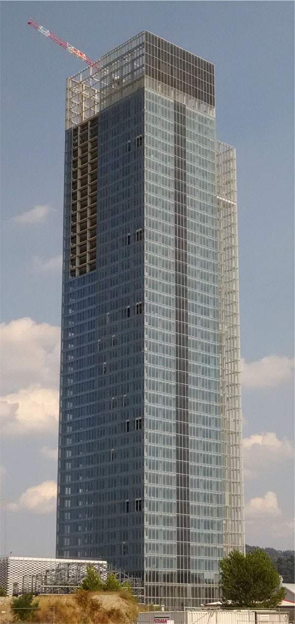
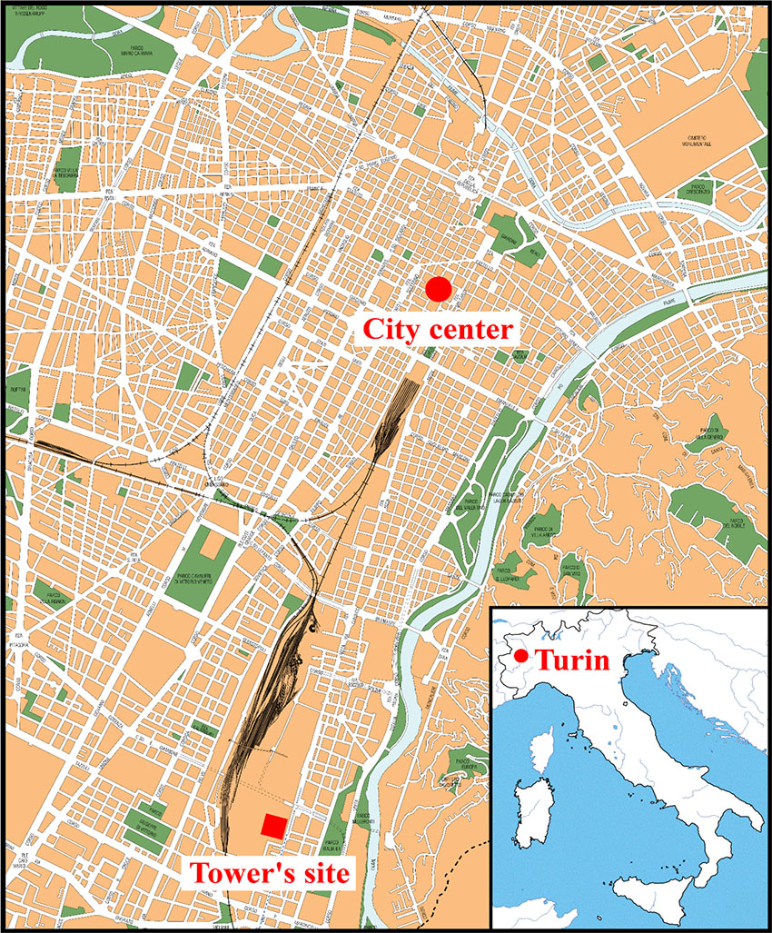
The building is situated in the south of the City of Turin in Italy (Fig. 2). Previously on this site, classified by the local authorities as an abandoned industrial area before the new constructions, there was the old manufacturing district of Fiat Avio. Near the new skyscraper, there is the “Oval” Olympic Winter Building, the Lingotto shopping center and auditorium. It is important to point out that the site will be well served by public transport by means of the new underground station on the Nizza street side, and the Lingotto railway station.
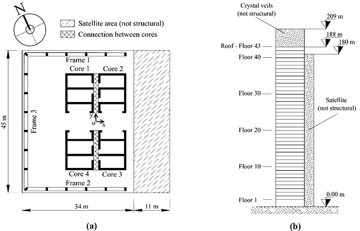
The multi-storey building base is square, measuring 45 m on each side. The tower comprises 43 floors above the ground, each level is 4.27 m tall (except the entry-hall, which is 8.66 m tall), therefore its height is about 188 meters up to the last floor. Beyond this level, there is a covered garden, 21-meters high, made of steel and glass walls. Considering the roof of the garden, the building reaches 209 m in height. On the east side of the tower, there are the so-called “Satelliti”, i.e. non-structural slabs 11 m in length, linked to the façade. For this reason, these decorative elements do not influence the total structural stiffness of the building, and they are not taken into account in the analytical model. The east side façade is 180 m tall and it is composed of a self-supporting steel frame linked by means of a limited number of connections to the reinforced concrete structure.
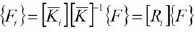
The building is characterized in its entire height by a regular structural scheme. In particular, the tower floor plan embeds 4 central cores with open thin sections and made of high performance concretes (Fig. 3).
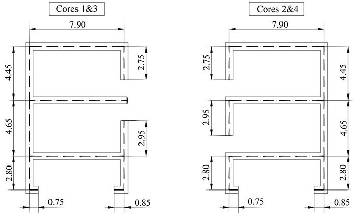
Cores 1 and 3 have the same size on the plans and the same thickness (0.50 m), like cores 2 and 4. These are arranged polar-symmetrically on the plan, in relation to the origin of the reference system, as shown in Fig (4).
From a structural point of view, the stiffness of these elements braces the tower by limiting transversal displacements in an optimal way. Along the building perimeter, excepting the east side, there are columns spaced 6 meters from each other, which reach a height of 188 m. Due to architectural requirements, the reinforced concrete columns have constant rectangular cross-section dimensions of about 1.10 m × 0.60 m, at all levels. The slabs, made of reinforced concrete, have a constant thickness of about 0.34 meters, while the slabs between the East and West cores are made up of concrete with a thickness of about 0.50 meters. The increased thickness is due to the need to link the slabs to the vertical cores, increasing their resistance and, at the same time, reducing the transverse displacements of the entire building due to horizontal loads.
The slabs in lightweight concrete are made by means of the Bubble Deck technique, i.e. by using polyethylene bubbles with a diameter of 225 mm embedded in the concrete casting. Adopting this construction technique, it is possible to reduce the slab weight by about 20-25% compared to its unlightened weight. This lightening, moreover, allows a better seismic structural behaviour and a considerable reduction of the axial stresses in the vertical elements to be obtained.
Different strength classes of concretes, depending on the axial loads, were used to made the other types of vertical structural elements in the structure. In particular, on the first floors the columns are composed of C70/85 class concrete, while on the upper floors of C35/45 class concrete. The cores are made of class concretes from the C60/75 - C30/35 range.
The designers analyzed the structure taking into account wind, seismic, and gravity loads, by means of a FE software program. Due to the low level of seismic activity in the area (Peak Ground Acceleration (PGA) ≤ 0.05 g), the wind load was recognized as the main horizontal action. Linear dynamic analysis, in addition to the previous one, allowed the natural resonant frequencies and their related modal shapes to be obtained.
3. COMPUTATIONAL MODEL
3.1. Analytical Model
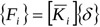
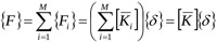
The numerical model, implemented in the Matlab computation code, is based on Carpinteri’s analytical formulation [48]. This considers an N-floor building, consisting of M vertical bracings, and has only three degrees of freedom per floor, since the displacement vector {δ}={ξ, η, ϑ}, which is the main unknown of the problem, consists of two translations along the x and y directions and a rigid rotation of the floor. The other unknowns are represented by the load vector {Fi}, i.e. the loads distributed on the i-th resistant element, generated by the external loads applied to each floor {F}={px, py, mz}. This last vector is made up of two concentrated loads acting in the x and y directions and a plane torsional moment.
In the analytical formulation, originally proposed by Carpinteri [48] and subsequently developed in [49-55], all vertical bracings, which can have a closed or open section, are connected to each other at the level of each floor of the building by slabs infinitely rigid in their own plane, but infinitely deformable outside the plane. Each vertical bracing is localized by its own local reference system, originating in the shear center of the section and with axes parallel to the main directions of inertia. All the geometric characteristics of the section, and therefore the local stiffness matrix of the bracing
 refer to this reference system. When the stiffness matrix of the single bracing
is known, we can write the following equation:
refer to this reference system. When the stiffness matrix of the single bracing
is known, we can write the following equation:
 |
(1) |
Subsequently, by defining an arbitrary global reference system (in this case the origin is placed at the centroid of each floor with the axes parallel to the sides of the building), the global equilibrium equation allows the stiffness matrix of the entire building to be written:
 |
(2) |
The vector of the forces acting on each bracing is obtained by means of the distribution matrix [Ri]
 |
(3) |
when the vector {Fi} is known. Inverting the Equation (1) determines the rigid plane displacements {δ}.
For details of the procedure see [58].
This type of approach can also be used to carry out the dynamic analysis of the structure because, according to D'Alembert's Principle, the inertial forces that arise by multiplying the acceleration by the mass of each plane can be considered as static forces and, consequently, can be added to the equation of global equilibrium. By solving the eigenvalue problem, we define the specific vibration frequencies and the modal forms.
The study of the structure was carried out on a simplified model of the building in which constant core thicknesses and constant mechanical properties along the height were considered. This choice is justified by the fact that, in the preliminary design phase, we do not have complete knowledge of the behavior of the structure in order to optimize the sizing. Subsequently, once the main parameters that characterize structural behavior have been identified, the structure is optimized and, finally, a more accurate model can be analyzed with a Finite Element program. For this reason, also the mechanical characteristics of the materials were homogenized with reference to the average resistance of the elements weighed on the number of floors. Following this procedure, an elastic modulus equal to 39 GPa was used for the frame elements, with 35 GPa for the cores, while a Poisson coefficient of 0.18 was assumed for all the elements. As far as the dynamic analysis is concerned, only the structural masses related to the slabs were considered. These were determined considering a specific weight of 18.75 kN/m3.
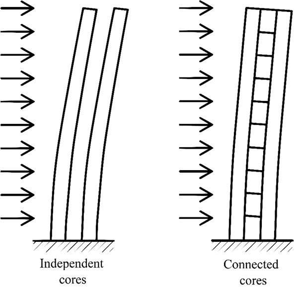
As already mentioned, core pairs 1-2 and 3-4 are connected by thickening the floor slabs (Fig. 5). These connections stiffen the structure and reduce the transversal displacements, as shown in Fig. (6).
In this case, because the cores are less than two meters apart and the slabs are 0.50 meters thick, the connection can be considered infinitely rigid out of the plane.
To calculate this structure correctly, the original analytical formulation was changed, developing a computation method based on the equivalent flexural stiffness. Since the effect of the connection is to join the sections of the two cores, in addition to the local reference system of each core, it is also possible to define a further reference system for each pair of connected cores. The origin of this reference system lies in the centroid of the section made up of the two cores. Consequently, the geometric characteristics of each core (and therefore the local stiffness matrices) refer to this last reference system. Finally, as previously illustrated, we calculate the global stiffness matrix and, in order to solve the structure from the distribution matrix, we obtain the forces acting on each core and, ultimately, the stresses and displacements of the structure.
3.2. FEM Model
Following the same assumptions adopted for the analytical model, in order to validate the results, a Finite Element Method Model (FEM model) was also created using a commercial software program.
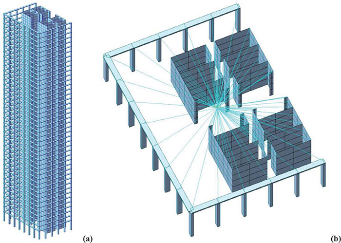
The three frames, four cores and infinitely rigid slabs in their plane were therefore modelled (Fig. 7a). Beam elements were used for the frame and shell elements were used for the cores, while the floors were modelled using rigid links that connect all the points of the plane to a master node coinciding with the geometric centroid of the slabs (Fig. 7b). At this point, the concentrated forces, corresponding to the externally applied loads for the static analysis and the mass of the planes for the dynamic analysis, were applied. All the structural elements are mutually interlocked and anchored to the ground. In this way, a FEM model similar to the analytical model was generated. The FEM model implemented is characterized by 69212 nodes, 1576 beam elements and 66960 shell elements. The amount of data to be analyzed required a much longer computational time (about one hour) than the time required for the analytical algorithm (a few minutes).
3.3. Wind Load
Wind, which is usually considered to be horizontal in direction, exerts actions on constructions that vary in time and space, generally causing dynamic effects that have an extremely important effect on high-rise buildings. In this work, in particular, only the load combination that maximizes the torsional effects induced by the action of the wind was considered, not taking into account the vertical loads induced by the dead load of the structure.
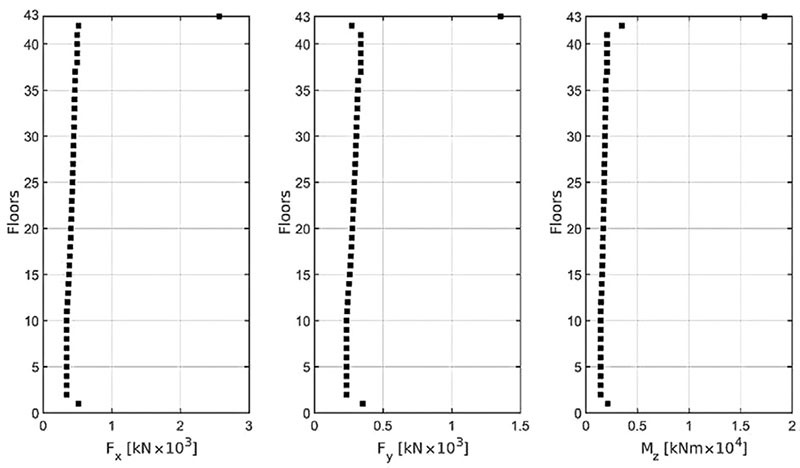
To analyze wind actions, sophisticated methods that require experimental analysis of the structure in a wind tunnel can be used. In the preliminary phase, the lack of detailed knowledge of the structure does not allow the application of these methods, so we used simplified methods. In the following analysis, the procedure proposed by Italian Rules - D.M. 14th January 2008, which reports the same formulation contained in the European Standard EN 1991 (Eurocode 1), was used. The calculation of wind forces depends on the geometric and dynamic characteristics of the structure, the geographical position and the characteristics of the site where the structure is located. Therefore, it requires the determination of certain parameters, primarily the reference wind speed, which in this case corresponds to 25 m/s. Given the importance of the building, a return period of 200 years is considered. Using these data, a kinetic reference pressure of 420.10 N/m2 was obtained. The wind pressure acting on the building is given by the product between the kinetic reference pressure and other coefficients concerning the exposure, shape and dynamics of the structure, which can be calculated using a detailed procedure indicated in Eurocode 1. When the pressures acting on the vertical surfaces of the building are known, it is possible to calculate the forces to be applied to each floor in relation to the areas impacted by the wind. The graphs in Fig. (8) show the forces applied on each plane of the model, referring to the origin of the reference system as shown in Fig. (3). We can see that in correspondence to the last floor, at a height of 188 meters, there is a drastic increase in forces because the wind pressure acting on the surface of the veils was also considered. For the same reason, the forces applied on the first floor are greater, as the inter-floor space is 8.66 meters high. Finally, at a height of 183.73 meters, the Fy force is reduced as a result of the reduction of the area exposed to the wind.
4. RESULTS
The results of the structural analysis are summarized in graphs that show the comparisons between the Analytical Model and the Finite Element Model considering the horizontal displacements of the centroid of each floor, and the stresses and strains on the vertical resistant elements. As regards the stress computation, the effects due to bending and secondary torsion were considered, leaving out the component due to vertical forces. This choice was made because, as previously mentioned, the aim of this work is to study mainly the torsional effects in high-rise buildings, ignoring the effects due to vertical loads.
Finally, the dynamic analysis carried out by applying the General Algorithm has determined the primary frequencies of the structure and the relative modes of vibration.
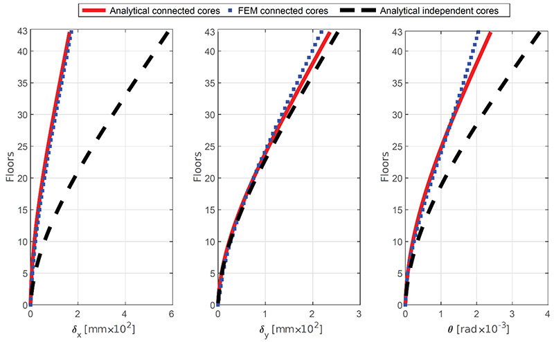
4.1. Displacements
Fig. (9) shows the displacements of the structure in the x and y directions as well as the rotations of the planes. Three models have been created: two models are analytical and show the displacements obtained by applying the General Algorithm, considering cores 1-2 and 3-4, respectively, as not connected, or rigidly connected using the technique previously illustrated in Section 3.1; the third model was obtained using a commercial FEM software program.
From the graphs, the rigid connection between the cores determines a reduction of about 70% of the transversal displacement in direction x, and a reduction of 45% of the plane rotations. A slighter reduction of the displacement in direction y is also evidenced. As a result, the analytical results of the model with the rigid connections show minimal differences compared to the FEM model. With these graphs it has been demonstrated that the connection between two or more cores, achieved by thickening the floor, is a simple structural choice that permits a drastic reduction of the horizontal displacement at a negligible additional cost compared to other structural solutions (i.e. outrigger) that would allow the same deformation levels to be achieved.
4.2. Internal Reactions
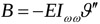
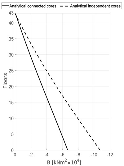
When the rigid rotations of plan ϑ are known, Vlasov's theory [34] can be used to determine bimoment (B), the primary torsional moment (MzSV) and the secondary torsional moment (MzVL) acting on each bracing through the following equations:
 |
(4a) |
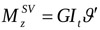 |
(4b) |
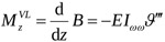 |
(4c) |
where Iωω and It indicate the sectorial moment of inertia and the torsional stiffness factor of the section of the considered core respectively, while E and G indicate the axial and tangential modulus of elasticity of the core material, respectively.
Fig. (10) shows bimoment on core 1, which is maximum at the base (warping prevented) and null at the top (free end). Also in this case the effect of the rigid connection with core 2 leads to a reduction in stress.
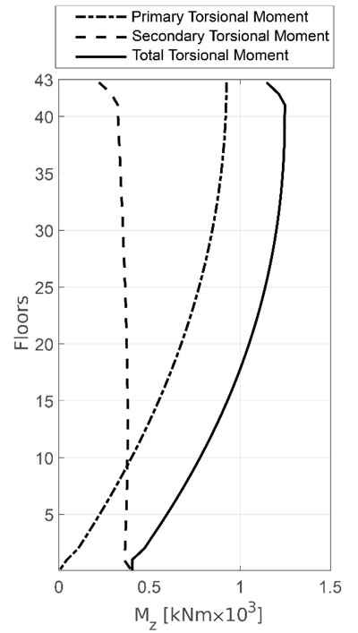
In the graphs shown in Fig. (11) we can see that the total torsional moment can be subdivided into primary (derived from Saint Venant's Theory) and secondary (derived from Vlasov's Theory). It is important to note that, in the section at the base, the primary torsional moment is null. This result is a direct consequence of the formulated boundary conditions, i.e. the fixed constraint prevents the warping of the section (i.e. ϑ′ = 0). In the top section, however, the sum of the total torsional moment acting on the four cores is equal to the externally applied moment. In the intermediate sections, the trend is determined by the first and third derivative of the plane rotations as illustrated in the Equations (4b and c).
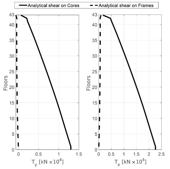
Observing Fig. (12), where the shear diagram is shown, we can see that the frames, due to their weak stiffness, do not contribute to stiffening the structure with respect to the horizontal load. The horizontal load is almost entirely absorbed by the four central cores, while the frames, arranged around the perimeter of the building, take on considerable importance only in order to absorb the vertical loads.
4.3. Stresses
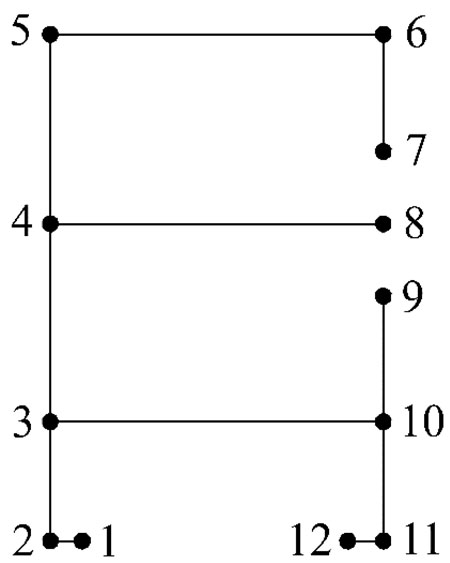
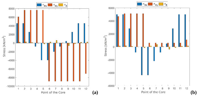
A schematic representation of core 1 is shown in Fig. (13). Moreover, in order to verify the reliability of the results of the analytical model, a comparison in terms of displacements, and in terms of stresses for core 1 are reported in Figs. (14) and Fig. (15).
Fig. (14) shows the comparison between the stresses in the base section of core 1, evaluated by the analytical model with the independent cores (Fig. 14a) and by the analytical model with the rigidly connected cores (Fig. 14b) respectively.
The standard stresses due to the wind load in the section of the base are obtained by the following equation:
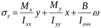 |
(5) |
where Mx and My indicate the bending moment with reference to the x and y axes, B indicates bimoment, Ixx and Iyy indicate the moments of inertia with respect to x and y, and ω indicates the sectoral area.
Assuming that the bending moments of the two models are almost identical, we can make two important observations. First of all, we can see that, by connecting the cores, the stresses due to My present the same sign in every point of the core because the neutral axis no longer referred to each core, but to the section made up of the two cores (Fig. 6). In this case, the rigid connection causes tensile stress in all points of core 1 and compressive stress on all points of core 2.
The second observation concerns the modulus of stresses (Fig. 15) in that, connecting the cores, the stress due to My is drastically reduced because the moment of inertia of the section made up of the two cores connected together is much greater than that of the single core. The same effect is seen on the stresses induced by warping, although in this case, the reduction of stress is due to the reduction of warping, because the sectorial moment of inertia is the same in both models.
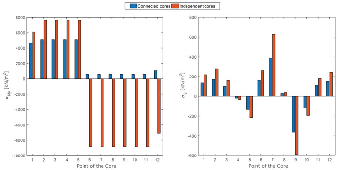
However, in this case, the stresses induced by warping do not have much influence over bending stresses.
The result was predictable because the geometry of the building, in this case, is quite regular. Moreover, the designers, wishing to limit the torsional effects as much as possible, arranged the cores in such a way as to generate polar symmetry, limiting the effects due to the asymmetries present in each core.
4.4. Dynamic Analysis
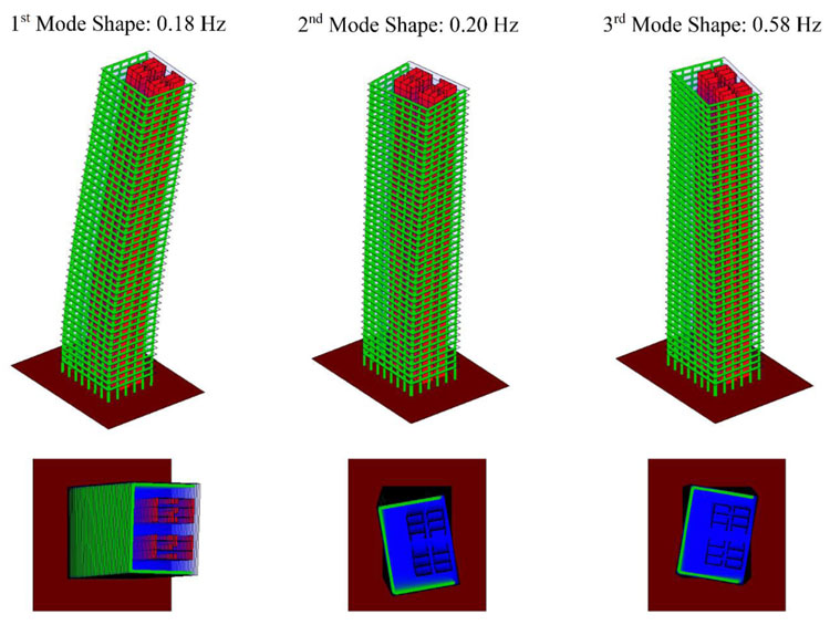
As far as the dynamic analysis is concerned, we considered the volume weight of the slabs to be 18.75 kN/m3 and consequently the mass of each floor was calculated. The General Algorithm was used to calculate the vibration frequencies and the mode shapes of the structure. Fig. (16) shows the first three modes of vibration. We can see that mode 1 is predominantly bending, while modes 2 and 3 are predominantly torsional.
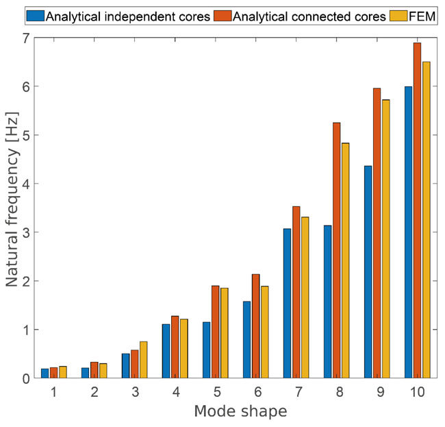
The frequencies of the first ten vibration modes are shown in Fig. (17). In this case too, the rigid connection between cores 1-2 and 3-4 makes it possible to obtain the vibration frequencies of the analytical model that lean towards those of the FEM model. In addition, the graph shows greater accuracy for the first vibration modes, and while there are larger differences for the others, this can be accepted as a first approximation.
CONCLUSION
In the preliminary phase of the structural analysis of tall and complex buildings, it is convenient to refer to algorithms based on simplified assumptions that make it possible to solve this problem while supplying reliable results.
This paper used the analytical formulation proposed by Carpinteri [48], and subsequently developed [49-55] as the so-called General Algorithm, which permits the static and dynamic analysis of tall buildings characterized by different resistant structural systems, to perform the structural calculation of the Piedmont Region Headquarters Tower. The structural peculiarity of this building consists of the coupling of the central cores through the stiffening of the portion of the floor between them. In particular, it has been demonstrated that this structural solution permits a drastic reduction of the transversal displacement of the structure. This has led to a small but important change to the General Algorithm, which was not previously intended to analyze structures stiffened in this way.
The results obtained were compared with those produced by a FEM program. The comparisons concerned the displacements, stresses and modal frequencies of the structure. This analysis also made it possible to detect the differences in terms of the computational time between the two models.
Although the constructed FEM model was characterized by a very large number of degrees of freedom of the structure, and therefore by much longer computational times than the analytical model, the results between the two computational models are almost completely comparable.
The analysis carried out shows that the use of simplified algorithms can be a valid tool of analysis in the preliminary design phase. Specifically, the algorithm proposed by Carpinteri [48] provided reliable results in short computational times, as well as the possibility of determining the key parameters that manage structural behavior. Clear knowledge of how the “structure works” makes it possible to understand how to optimize the system studied and hence continue detailed analysis with finite element programs.
CONSENT FOR PUBLICATION
Not applicable.
AVAILABILITY OF DATA AND MATERIALS
All the geometric and mechanical data on the Piedmont Region Headquarters Tower in Turin, have been obtained from documents produced by the staff designers.
The considered documents are available in the following web-sites:
(1) http://www.ecsd.it/wp-content/uploads/2014/05/9_NS RP_Afternoon_Presentation.pdf
(2) http://www.poli-listaperta.it/wp-content/uploads/2012 /10/Mola_Franco_Giornata-IV_NSRP_Final1.pdf
FUNDING
For the creation of this manuscript, the authors do not received specific public or private funding, except the regular remuneration provided by Politecnico di Torino to carry out teaching and research activities.
CONFLICT OF INTEREST
The authors declared no conflict of interest, financial or otherwise.
ACKNOWLEDGEMENTS
The authors are grateful to Eng. Domenico Vigorita for the kind collaboration in analyzing the data of the Piedmont Region Headquarters Tower original project.

