All published articles of this journal are available on ScienceDirect.

Numerical Analysis of the Dynamic Responses of Multistory Structures Equipped with Tuned Liquid Dampers Considering Fluid-Structure Interactions
Authors Info & Affiliations
Abstract
Background:
A tuned liquid damper (TLD) is a remarkable damping device that can be used for almost any type of structure. In the previous research on TLDs, the effect of the liquid pressure acting on the tank walls was ignored by assuming rigid tank walls, thereby neglecting the fluid-structure interaction (FSI) phenomenon. However, this could lead to errors in designing TLDs and the failure of the water tanks serving as TLDs.
Aims:
For this reason, this paper studies the influence of the tank wall’s flexibility on the effectiveness of a TLD.
Method:
Ansys V.11 was employed to analyze high-rise buildings under harmonic and seismic loadings with and without a TLD.
Results:
The results show that a TLD is very useful in mitigating the vibration response of a 14-story building subjected to dynamic loading. Furthermore, an 8-story building was analyzed with and without a TLD considering the flexibility of the tank wall. The dynamic response of the 8-story building subjected to harmonic loading with a rigid TLD remarkably reduced; in contrast, the flexible TLD did not prove to be as efficient as the rigid TLD.
Conclusion:
This study contributes to the literature by considering the FSI in the design of a roof water tank as a TLD. Moreover, the authors proposed a tank flexibility parameter to distinguish between rigid and flexible tanks that could help engineers more accurately and quickly design water tank TLDs.
1. INTRODUCTION
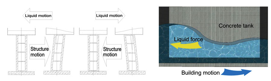
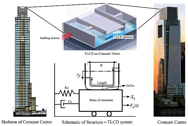
In general, a Tuned Liquid Damper (TLD) constitutes a tank filled with liquid that relies on the sloshing of that liquid to dissipate vibration energy (Fig. 1). This device bears many advantages, including its low cost, ease of installation and infrequent need for maintenance. TLDs can be applied to almost any type of structure, for example, high-rise buildings, towers and chimneys, including an existing structure [1, 2]. A TLD operates according to the mechanism wherein a water tank is designed to have a natural frequency similar to that of the structure that needs to be controlled. Resonance occurs based on this principle; the resultant sloshing of liquid inside the tank helps change the dynamic characteristics of the structure. Moreover, the liquid pressure inside the TLD acts on the tank wall and swings the building back to its original equilibrium position. However, this pressure from the liquid could also damage a flexible tank due to Fluid-Structure Interaction (FSI), which should not be ignored for very large TLDs.
In previous studies on sloshing liquids in TLDs, researchers simply ignored the effect of the liquid pressure acting on the tank walls by assuming that the tanks are rigid [3-6]. Currently, tanks regularly fail because of FSIs; conseq- uently, this phenomenon cannot be ignored when designing tanks in general (or when designing TLDs in particular). One of the first studies on the influence of the FSI on the working ability of TLDs was conducted by Gradsincak [7, 8]. Because of the complexity in solving the coupling equations at the tank-liquid interface, very few numerical studies have simulated both the fluid and the structure in a single calculation model while considering the FSI to investigate the role of this interaction in designing TLD liquid tanks [9-11]. Eswaran recently conducted studies on the damping capacity of TLDs for multistory buildings [12, 13]; the interaction phenomenon was taken into account with an FSI analysis algorithm by combining semi-experiments to investigate a three-story steel frame under dynamic loads with and without the use of a TLD as a damping device.
In another recent investigation, Zhu et al., [14] used the Real-Time Hybrid Simulation (RTHS) method to demonstrate the performance of a 9-story building using a Modified TLD (MTLD) as a seismic resistance device while examining how the interaction between the structure and soil affects the working efficiency of the TLD. Chang et al., [15] investigated an MTLD by analytical and experimental testing; the MTLD utilized a rotational spring system at its base, and therefore, the swaying structure experienced combined horizontal and rotational motions. In Chang’s study, the RTHS method was employed to verify the most important parameters of the TLD, including the dimensional rotational stiffness parameter, frequency ratio and damping ratio. The FSIs of TLDs were also analyzed through calculations of the sloshing pressure acting on the tank wall, where the tank served as a damper; these types of TLDs have an internal baffle to increase the inherent damping, thereby improving the device performance [16]. Guo et al., [17] analyzed the vibration reduction of a cantilever beam with an interior sloshing absorber, and Ansys was applied to simulate the dynamic beam suppression load. Furthermore, Fu et al., [18] investigated the damping performance of a new type of TLD composed of a tuned mass damper and a liquid sloshing damper to reduce the vibration of a structure. Subsequently, Xu et al., [19] optimized and utilized a device comprising a tuned mass damper combined with a TLD to control structural vibrations.
2. METHOD
This paper analyzed two kinds of multistory structures subjected to harmonic and seismic loadings with and without a TLD. In this study, the effects of FSIs on the specific characteristics of the tank, as well as the effects of the fluid pressure acting on the tank wall, were analyzed. Then, the effectiveness of the TLD was investigated in cases using a flexible tank and a rigid tank. In addition, the flexibility of the tank wall, the moments in the structure, and the top displacements of the structure were considered. For this purpose, a numerical method was used with commercial software to model the structure and investigate the thickness of the tank wall to describe the relations of rigid and flexible TLDs.
2.1. The FSI in a TLD
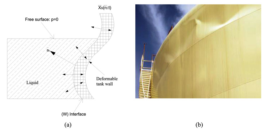
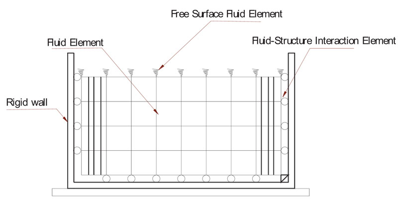
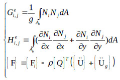
A TLD is a passive damper device that relies on shallow liquid sloshing within a tank to suppress the horizontal structural vibrations induced by wind or other dynamic loads. The previous research assumed that the tank wall is rigid to bypass the FSI between the sloshing liquid and the tank, thereby ignoring the complexity of solving the coupling equations at the liquid-wall interface. However, in recent years, computing technology has been improved and thus can consider the failure of tanks due to frequent sloshing. On one hand, the TLD mechanism based on the resonance frequency of a sloshing liquid helps promote the maximum ability of the TLD; on the other hand, this mechanism changes the TLD’s dynamic properties through the fluid-tank wall interaction. The main problem in studying the FSI, in this case, is solving the boundary condition at the tank walls. Fig. (2) shows how the sloshing of a liquid could damage a flexible tank.
Modern buildings are being built of considerably greater heights, requiring TLDs to become larger in turn. As the size of the TLD increases, the fluid pressure acting on the tank wall becomes more significant to the point where it is impossible to consider the tank wall to be rigid [9, 10]. For example, the 58-story Comcast Center (Fig 3) in Philadelphia, USA (300 m high), employed a very large 1100_m3 water tank as a TLD. Hence, the volume of liquid inside the tank is too large to ignore the FSI phenomenon by assuming that the tank wall is rigid.
2.2. Analysis Method for the Tank-Fluid System
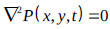
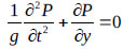
In the liquid domain, the hydrodynamic pressure distribution is governed by the pressure wave equation. Assuming that (1) the volume of the tank is small, (2) the water is incompressible and has a negligible viscosity, and (3) the velocity of the pressure wave is infinite, then, the motion of water is written as [10]:
 |
(1) |
where P(x,y,t) = hydrodynamic pressure.
From [11], the liquid pressure in eq.(1) is determined by ground excitations of the walls and bottom of the tank. The motion of these boundaries is related to the liquid pressure via the boundary conditions. For ground excitations, the boundary condition at the tank wall-liquid interface can be described as:
 |
(2) |
where ρ = density of the liquid and an = acceleration of the tank wall’s boundary along the direction as shown in Fig. (2a).
For the rigid tank shown in Fig. (4), the acceleration on the right side of eq. (2) is the ground acceleration, but for a flexible tank, this term serves as the ground acceleration plus the relative acceleration of the flexible tank wall. Considering the small-amplitude gravity force of the sloshing liquid on the free surface, the resulting boundary condition is given as [11]:
 |
(3) |
where y = vertical direction and g = gravitational acceleration.
Ignoring the effects of this gravity force leads to the free surface boundary condition, which is appropriate for the impul- sive motion of the liquid. The related governing equation is given as eq. (3):
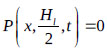 |
(4) |
where Hl = height of liquid in the tank.
Using finite-element discretization and the discretized for- mulation of eq. (4), the fluid equation can be written as follows:
 |
(5) |
where  and
and  . The coefficients
  and
and  for the individual elements are expressed as follows:
 |
in which:
 |
(6) |
where Ni = mode shape of the ith node in the liquid element;  = acceleration vector of nodes in the structure domain;
  =ground acceleration vector subjected to the structure; and
  = coupling matrix. le and Ae represent the integrations over the side and area of the element, respectively.
In eq.(5),  and
and  are constants, while the force vector
  , pressure vector
  , and its derivatives are variable quantities. In the fluid-structure coupling equation, the pressure is exerted on the interface as external loads on the tank walls. The general fluid-structure equation can be written as:
 |
(7) |
where [M], [C] and [K]= mass, damping and stiffness matrices of the structure, respectively, and [C’] = the damping parameter of the liquid matrix. This damping parameter depends on the viscosity of the fluid and on the wave absorption in the liquid domain and along its boundaries. The matrix [Q] transforms the liquid pressure on the tank wall and the structural acceleration into the liquid domain. With two-node interface elements with x and y transitional Degrees of Freedom (DOFs) at each node on the surface of the tank and the corresponding two-node interface elements with a pressure DOF at each node attached to the fluid elements, the coupling matrix is expressed in eq. (8) as:
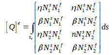 |
(8) |
where Nf and Ns = shape functions in the fluid and structure domains, respectively. Additionally, η and β are the direction cosines of the nodes of the surface element on the wet face of the tank. The direct integration scheme is used to find the displacement and hydrodynamic pressure at the end of time increment i+1, given the displacement and hydrodynamic pressure at i. The Newmark-β method is used in which 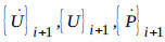 and
and  can be written as follows in eq. (9) as:
 |
(9) |
It is difficult to find the eigenvalues of large matrices. Many studies have addressed this problem; accordingly, Ansys can be used to simulate the liquid domain and the main structure [9-11, 18-21]. The natural frequencies and amplitudes of the sloshing liquid are selected to emphasize the importance of the FSI. The tank’s wall, columns and beams are modeled by “Beam3” elements, and the liquid is modeled by “Fluid 79” elements. The FSI is achieved by coupling the displacements of the liquid and tank walls in the direction normal to the tank walls.
2.3. The Effect of the FSI on the Natural Frequency
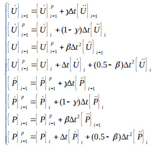
In previous studies, researchers assumed a rigid tank and ignored the thickness of the tank walls. Nevertheless, the wall thickness affects the characteristics of the water tank, especially its natural frequency. To clarify this point, four types of tanks with different tank wall thicknesses, t, were analyzed to find their natural frequencies, and then the results were verified by comparing them with the findings of previous studies on rigid tanks conducted by Sun et al. [5], Sun [6] Fujino and Sun [1], and Fujino et al. [2]. Afterward, the natural frequency of a flexible tank was obtained by the numerical method to show the difference between the cases with rigid and flexible tanks as well as the importance of the FSI. The tanks have dimensions of T0.59 × 0.03 (i.e., the tank width is 0.59 m, and the liquid height is 0.03 m, similar to the experimental tanks used in [1, 2, 5, 6]), T1.00 × 0.10, T3.00 × 0.20 and T6.00 × 0.50. The natural frequency of a tank is expressed as [1]:
 |
(10) |
where 2a = length of the tank and Hl = height of liquid in the tank.
The natural frequencies of the four tanks introduced above are shown in Fig. (5), and the results show good agreement with those obtained from eq (5,6). Moreover, the figure shows that a flexible tank wall remarkably affects the natural frequency. In this research, the relation between a flexible tank and a rigid tank can be denoted by ψ, a flexibility parameter that depends on the thickness of the tank wall, the liquid height and the liquid modulus:
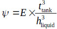 |
(11) |
where ttabnk is the thickness of tank wall, and hliquid is the height of liquid in the tank.
Table 1 shows that the natural frequencies of the rigid tank from the analytical solution in eq.(10) and the numerical method considered FSI are consistent. To understand the relationship between the rigid and flexible tank, the wall thickness of the tank varied from zero to infinity. The results show that the flexible tank wall greatly affects the natural frequency as shown in Fig. (5).
Fig. (5) illustrates the relationship between the natural frequency and the flexibility of the tank wall. The maximum frequency of a tank is the natural frequency of the rigid tank. Fig. (5) shows that the tank is rigid when ψ exceeds 100 (ψ ≥ 100); otherwise, the tank is flexible. Thus, the thicker the tank wall, the higher the frequency of the TLD. The flexibility parameter ψ can help the TLD design engineer to easily identify the rigid tank.
2.4. The Effect of the FSI on the Sloshing Amplitude
To clearly ascertain the effect of the FSI on the liquid sloshing amplitude, a numerical example is considered. The rectangular concrete tank shown in Fig. (6) has dimensions of 6.0 m×1.0 m×0.5 m×t (tank length, tank height, liquid height and wall thickness, respectively) and has an applied harmonic load of  with
with  . The properties of the concrete are as follows:
  ,
,  , and
, and  . The mass of the structure is 2894.1 kg. From eq. (10),
 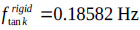 , and from numerical analysis,
  . Based on the flexibility parameter ψ given in eq. (11), this tank is rigid when
 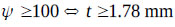 .
.
| Natural Frequency of Rigid Tank | |||
|---|---|---|---|
| T0.59 × 0.03 | T1.00 × 0.10 | T3.00 × 0.20 | T6.00 × 0.50 |
| Analytical | FEM | Analytical | FEM | Analytical | FEM | Analytical | FEM |
|---|---|---|---|---|---|---|---|
| 0.458 | 0.458 | 0.316 | 0.314 | 0.236 | 0.233 | 0.186 | 0.185 |


The tank is subjected to harmonic loading
with
and
 . The sloshing can be expressed as shown in Figs. (7a and 7b). It is clear that when the tank is rigid or nearly rigid (ψ ≥ 100), the sloshing amplitude is approximately the same (Fig. 7a), and the amplitude in the flexible tank is much greater than that in the rigid tank (Fig. 7b).
Fig. (7a and 7b) show that the FSI is important in tank design for two reasons: (1) the FSI leads to a change in the dynamic properties of the tank, and the natural frequency of the TLD can be easily adjusted by increasing or reducing the tank wall thickness. (2) Under the same load, the sloshing amplitude in the flexible tank is higher than that in the rigid tank. This implies that a flexible tank carries more load than a rigid tank; thus, when designing a TLD, the flexibility should be checked by the parameter ψ to protect the stability of the tank. Many tanks fail because of a rigid tank wall assumption, especially under dynamic loads.
3. NUMERICAL ANALYSIS OF TLDS CONSIDERING THE FSI
The dynamic response of a high-rise building subjected to a harmonic or seismic loading can be controlled by many types of damper devices. A TLD is a passive system that it does not require any external power to be operational [23, 24]. How- ever, the FSI phenomenon can affect the mechanism of a TLD, thereby changing the characteristics of the tank, especially its natural frequency, and can deactivate the device. Thus, the FSI should not be neglected when designing a TLD by assuming that the tank walls are rigid. In recent years, two methodologies have been commonly implemented to analyze the FSI in a TLD. (1) The first is the semi-experimental method, an example of which is the RTHS technique [14, 15, 21]. In the RTHS method, only the critical components (i.e., the experimental substructure) are tested physically, while the remaining parts (i.e., the analytical substructure) are modeled numerically on a computer. These two substructures are synchronized and coupled in real-time through an integration algorithm. (2) The second is the numerical method, that is, the application of Ansys, to model the structure [9, 17, 18, 25]. In this study, Ansys V.11 was used to analyze multistory structures in the following two sections to investigate the seismic resistance of TLDs. The first section presents the main concepts in designing a water tank as a damper device, and the second section shows the TLD’s capacity and emphasizes the importance of the FSI.
3.1. TLD Design for a 14-Story Building
The TLD design for a steel building, 70 m high under harmonic and seismic loadings, is illustrated in Fig. (8a). El Centro earthquake data were used to analyze the seismic resistance of the building, and the numerical model of the building is shown in Fig. (8b). The Newmark-β method was used to predict the sloshing of the liquid and the deformation of the top of the building. The building has 14 stories, with each story of 5 m height, and one span is 3 m in length. All of the beam and column sections are the same, and the tank dimensions are  with
with  ,
,  and
and  . The mass of the structure is
  .
.
The TLD was designed based on Yu’s work [4] and Ashasi’s study [21]; that is,  and
and 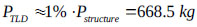 . Two conditions can be described as follows:
 |
(12) |
where bt and hf are the tank width and liquid height, respectively. The liquid in the TLD is water with 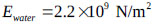 ,
,  and
and  . From eq.(12), with two equations and two unknowns, we obtained bt ≈ 1.2 m and hf = 0.5 m. Then, the natural frequency of the TLD following (10) was fTLD = 0.749 Hz. The building was subjected to harmonic loading of
  with load frequencies ranging from 0 to 1.2 Hz in addition to the loading of the El Centro earthquake with and without the use of a TLD to suppress the structural vibration. Figs. (9 and 10) show the responses of the structure with and without a TLD. In Fig. (9), the deformation at the top of the building decreased by a factor of four (from 0.073 m to 0.00189 m) when using a TLD, and resonance occurred at an exciting frequency of f = 0.94 Hz with the TLD.

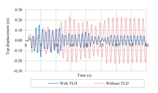
Fig. (10) shows that the TLD helps mitigate seismic vibration by up to 82.35% (0.217 m to 0.0383 m). This result is in good agreement with the work of Ashasi [21].
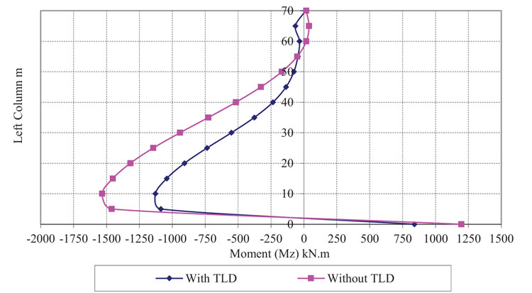
In addition, the moments in the left column of the structure with a TLD (1128 kNm) are less than those without a TLD (1533 kNm), as shown in Fig. (11), with a reduction of nearly 26.4% (Fig. 11).
3.2. The Effectiveness of the TLD and the Effect of the FSI
In this section, an 8-story steel building is considered that has one span 3.0 m in length, and each story is 3.0 m in height, with  ,
,  and
and  . The mass of the structure is
  . The fundamental frequency of the structure is
  , and the other modes of the natural frequency are shown in Table 2.
The frequency-domain analysis was carried out to identify the response vibrations of the structure with frequencies ranging from 0 to 1 Hz. The maximum response vibration of the structure without a TLD was 1.89 m at the frequency f = 0.29 Hz, being equal to the natural frequency of the structure.
The TLD was designed by the same process as described for the example shown in section 3.1 to suppress dynamic vibrations, and the TLD selected had dimensions of LTLD × hliquid = 2.0m × 0.2m,
 and
and
 . The thickness t of the tank varied to investigate the effectiveness of the FSI. The thickness t of the tank wall was separated into two types: rigid and flexible. Fig. (12a) describes the response vibration of the building with a nearly rigid TLD; ψ ≥ 100 reduced by 50%, and resonance occurred at f = 0.29 Hz, which is the same as the natural frequency of the building. However, as shown in Fig. (12b), resonance occurred uncontrollably and at an undefined value. Thus, the flexibility of the TLD must be considered during the design process.
The seismic resistance of the structure with a TLD subjected to the El Centro earthquake loading was further analyzed. The Newmark-β method was utilized to track the sloshing liquid and top displacement of the 8-story building. When the structure was subjected to the seismic loading, the TLD got activated, and the liquid sloshing exhibited oscillatory behavior, as shown in Fig. (13).
| Natural frequency Hz | Mode 1 | Mode 2 | Mode 3 | Mode 4 |
|---|---|---|---|---|
| 0.2985 | 0.89582 | 1.5681 | 2.3326 |
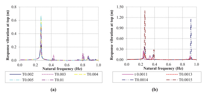
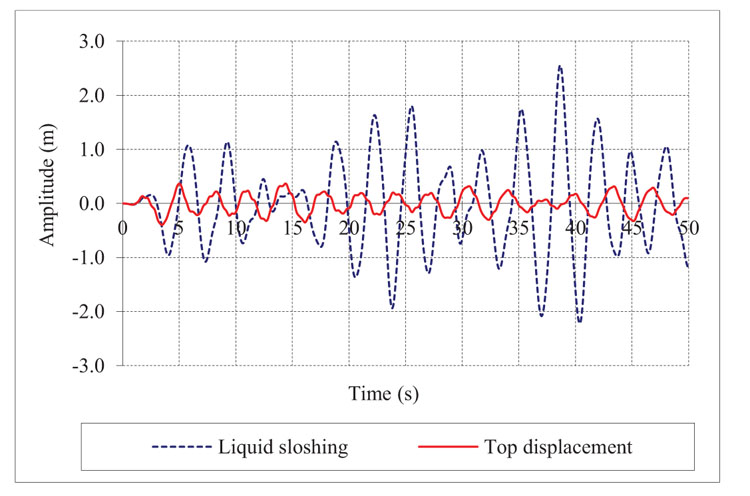
Fig. (13) shows that the liquid sloshing occurs in a phase opposite to that of the structural vibration; this represents the mechanism of the TLD illustrated in Fig. (1). This liquid pressure inside the TLD acted on the tank wall and brought the building back to its equilibrium position. Moreover, the TLD helped reduce the top displacement by 66.14% (from 0.576 m to 0.195 m), as shown in Fig. (14).
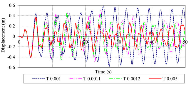
However, various top deformations were observed with different tank thicknesses, as illustrated in Fig. (15), the thickness of the tank wall proved to be effective in controlling the seismic resistance. A rigid TLD (thickness t > 0.005 m) helps to reduce the vibration better than a flexible TLD.
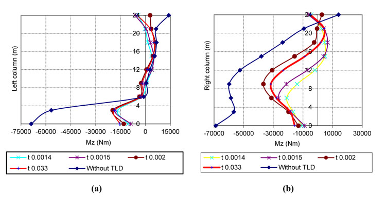
To illustrate the seismic resistance capacity of the TLD more clearly, the moments in the columns of the building are illustrated in Fig. (16a and 16b) for the cases with and without a TLD. The use of a TLD can reduce the moment in a column from 50 to 75%; this finding is in good agreement with the findings shared by Sun et al. [5], Sun [6] and Fujino and Sun [1] and Fujino et al. [2] who performed an experiment in 1989.
From Fig. (16), it is easy to recognize that a TLD significantly helps control the structural vibration . The flexible tank affects the internal column’s moment (10% in the left column to 35% in the right column). However, the impact of the liquid pressure on the tank wall is much more important and could cause the water tank to fail before the building can swing back to its equilibrium position. This could constitute the topic of a future study: the deformation of the tank wall needs to be verified experimentally, and multiple TLDs could be used.

4. RESULTS AND DISCUSSION
This study analyzes the natural frequency of four types of tanks and compares the results with the previous research [1, 2, 5, 6]. From past studies, the fluid-structure interaction was ignored and the wall tank was considered rigid [11, 26]. However, investigations carried out in this research demonstrated that wall flexibility has a major effect on the seismic behavior of the liquid tanks and should be considered in their design [9, 10]. Also, this study investigated the below two points: (a) the characteristics of the TLD considering FSI (natural frequency in Fig. (5) and sloshing in water tank during earthquake in Figs. (7 and 13), and b) the vibration control of the structure subjected to harmonic and seismic loading with and without TLD.
With the rigid or near rigid TLD, the natural frequency, sloshing and dynamic response of the structure are similar to that of the FSI as shown in Figs. (5, 7a, 12a, 15 and 16). However, when the tank wall is relatively thin, the FSI phenomenon affects remarkably the performance of the TLD (Fig. 15). Especially, the deformation of a water tank as TLD could lead to the failure of the tank [20]. In this case, the damper is inactivated during the earthquake and should be taken into consideration when designing TLD. For the selection of the thickness of the tank wall, the engineer could use the flexibility parameter as shown in equation (11).
TLD helps mitigate vibration of the structure significantly as shown in Figs. (10 and 11) (for 14-story building) and Figs. (15 and 16) (for 8-story building). Also, TLD significantly reduces the top displacement of the structure. The flexible tank also affects the internal column’s moment (10% in the left column to 35% in the right column). However, the liquid pressure impact on the tank wall is much more important. This could lead to the failure of the water tank before the building can swing back to the balance position. The deformation of the tank wall needs to be verified by the experiment and Multi TLD (MTLD) could be used to avoid the FSI phenomenon.
CONCLUSION
A TLD can be designed easily, as described in sections 3.1 and 3.2, by adjusting the size of the tank and the height to which the liquid is filled inside. Moreover, TLDs can be applied to almost any structure. The vibration at the top of a building subjected to a dynamic load can be reduced by up to 82.35% with a TLD. In summary, a TLD is a very good damping device for controlling structural vibrations. However, the FSI cannot be ignored when designing TLDs, as this phenomenon remarkably influences the effectiveness of a TLD. Thus, it is not safe to assume a rigid tank when designing a TLD. The impact of the liquid pressure on the flexible tank increases when considering the FSI phenomenon, which is very important and must be considered carefully. The FSI can change the dynamic properties of the water tank, rendering the TLD ineffective [9-11]. In this regard, the flexibility parameter could help engineers choose an appropriate tank thickness for either a rigid TLD or a flexible TLD. When a TLD is operational, there is no difference in the building’s internal forces between a rigid tank wall and a flexible tank wall, as shown in Figs. (16a and 16b). Therefore, the recommendation is that a TLD should be designed to have a rigid wall to avoid tank deformation due to the FSI.
In the 14-story building considered in this study, the top displacement under harmonic loading reduced significantly up to 74.1% (from 0.073 m to 0.0189 m), as shown in Fig. (9); similarly, the top displacement under seismic loading reduced by up to 82.35% (from 0.217 m to 0.0383 m), as shown in Fig. (10). The moment in the columns of the building reduced from 1533 kNm to 1128.4 kNm (26.4%), as shown in Fig. (11).
In the 8-story building without a TLD subjected to harmonic loading, the dynamic response of the structure reached 1.89 m when resonance occurred. Fig. (12) illustrates that the TLD is remarkably effective in controlling the dynamic structural vibration. The nearly rigid TLD in Fig. (12a) helped mitigate the structural vibration response from 1.89 m to 0.673 m (64.39%); meanwhile, the flexible TLD in Fig. (12b) was not observed to be as effective as the rigid TLD, as it reduced the top displacement by only 0.256 m (equal to a 13.54% reduction). The reason for this discrepancy was that the natural frequency of the TLD with a flexible tank wall was not equal to that of the structure, and thus, the device was not active when the building was subjected to either harmonic or seismic loading. When the 8-story building was subjected to the El Centro earthquake loading, the dynamic response of the building without a TLD was 0.576 m. With the rigid TLD (t=0.005 m), the corresponding reduction reached 66.14% to 0.195 m, as shown in Fig. (14), but the vibration mitigation performance of the structure with a flexible TLD in Fig. (15) was not as good as with the use of a rigid TLD. The top displacement reduced by only 44.64% (t=0.0012 m) or 60.71% (t=0.0011 m), and the TLD did not activate when the tank wall was 1.0 mm (t=0.001 m). This constitutes another reason why the FSI should be considered in the TLD design.
CONSENT OF PUBLICATION
Not applicable.
AVAILABILTY OF DATA AND MATERIALS
The data sets used and/or analysed during this study are with the corresponding author and can be made available on request.
FUNDING
None.
CONFLICT OF INTEREST
The authors declare no conflict of interest, financial or otherwise.
ACKNOWLEDGEMENTS
The authors appreciate all the employees at the Earthquake Laboratory for access to the laboratory at Ho Chi Minh University of Technology and Education. Any opinions, findings, conclusions and recommendations expressed herein are of authors.

