All published articles of this journal are available on ScienceDirect.

Influence of FE Modelling Approaches on Vulnerabilities of RC School Buildings and Proposal of a CFRP Retrofitting Intervention
Authors Info & Affiliations
Abstract
Background:
The vulnerability assessment of existing school buildings against earthquakes represents a priority concern for society. In recent years, several countries promote seismic rehabilitation projects of school buildings, including the allocation of funds to regions with high seismic hazard.
Objective:
This research aims to highlight some key role aspects related to difficulties encountered in the numerical modelling of RC structures hosting school activities.
This work evaluates the seismic vulnerability of school buildings located in the municipality of Trecastelli (Marche, Central Italy) to quantify the effective influence of typical and specific seismic vulnerabilities detected on the global seismic behaviour of each building.
The effectiveness of a possible Carbon Fibre Reinforced Polymer (CFRP) local strengthening intervention, for the case study, aimed to confine unconfined beam-column joints is also considered.
Methods:
Three different numerical models of a Reinforced Concrete (RC) school building are implemented with the lumped plasticity, the distributed plasticity (fibre) and the 3D Continuum Finite Element (FE) approaches. Nonlinear static (pushover) analyses are performed to assess the global seismic behaviour of the structure, and the limitations to represent the reality with different approaches. After the seismic vulnerability assessment of the case study, a CFRP retrofitting intervention is proposed to confine external beam-column joints.
Results:
The comparison of the numerical results of three models shows that the fibre model is the least suitable means to represent shear problems, while the lumped plasticity model is closer to reality than the previous one even if it does not take into account the concomitance of bending, shear and axial force and the interaction between them in the inelastic response. Of course, the 3D Continuum model is the most accurate representation to describe the complex and combined mechanisms developed in the joint panels. Nonlinear static (pushover) analyses carried out on unreinforced and reinforced structures of Continuum model demonstrate that the Fibre Reinforced Polymer (FRP) strengthening improves the displacement capacity of the structure.
Conclusion:
This study has highlighted the strengths and weaknesses of different modelling types. The meaningful information about mechanisms developed in joints given by the 3D Continuum FE model is useful to identify shortcomings of the design project and to conceive a retrofitting strengthening intervention.
CFRP sheets externally bonded on beam-column joints may improve the seismic frame performances without a significant change of the structural stiffness, promoting a ductile failure mode with a higher displacement capacity than the unreinforced case.
1. INTRODUCTION
The vulnerability assessment of existing public constructions against seismic actions, which is the prerequisite for their following protection, is a crucial issue in seismic prone countries. Mainly, school buildings play a key role in the social and cultural life of people. In seismic regions, some school buildings were built before the development of modern seismic design provisions or without considering seismic provisions at all, due to the evolution of seismic codes and seismic hazard classifications.
The architectural layouts of school buildings, also have to be considered, as their spatial configurations of the hosted learning facilities, result in irregular structures with intrinsically unfavourable seismic behaviour [1].
In recent years, several countries support seismic rehabilitation projects of school buildings, including the allocation of funds for regions with high seismic hazard [2]. Furthermore, several national and regional programs and activities are focused on the mitigation of the seismic risk of Italian public buildings, supporting the scheduling of the building structural safety assessment, the design and the execution of strengthening interventions [3, 4].
Nevertheless, the strong earthquakes that occurred in the last few decades in Italy; (Molise (2002), Abruzzo (2009), Emilia (2012), and Central Italy (2016)), confirm the susceptibility of this type of buildings to extensive damage, and the need for a high level of safety against both vertical and horizontal loads, and also the social importance of their fast re-opening after seismic events.
Field observation of structures damaged by L’Aquila earthquake demonstrated that the premature failure of partially confined beam-column joints is one of the leading causes that limits the global structural seismic capacity [5]. The repetitiveness of collapse mechanisms, highlighted on the earthquakes occurred, requires interventions to reduce or eliminate the original shortcomings of the design project to achieve the desired level of safety. For example, the weaknesses of the external beam-column joints in the RC frames or the fragility and poor connection of the infill walls to the frame are observable.
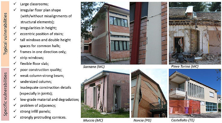
The results of the visual inspections of damage occurred in many school buildings after the 2016. The Central Italy earthquake sequence is reported in the photographic survey shown in Fig. (1) and associated with the vulnerabilities of school buildings. RC buildings show significant damage or, in several cases, the collapse of partition walls and ceilings, focusing on seismic performance of non-structural elements in the overall response of the structure.
Moreover, RC school complexes have usually insufficient technical joints between different buildings, especially for irregular configurations. In those cases, damage occurs to structural joints with a seismic pounding effect between buildings, which may lead to out-of-plane behaviour of infill walls.
First, the knowledge of school building typologies is a prerequisite, which leads to the definition of the associated typical and specific building vulnerabilities. An interesting study, that correlates seismic assessment of school buildings (belonging to lower levels of the Italian education system) and vulnerabilities, was carried out in [6].
The typologies of school buildings in Italy are strongly characterised by the construction period and the evolution of teaching strategies [7, 8].
In particular, the relationships between the shape of the building, the adopted pedagogical method, and the reference legislative code framework are investigated through a typological study on school buildings. Since the 60s and 70s rules establish the basic principles and the design to which contemporary schools refer. School buildings have to be conceived on concepts of correct sizing of spaces and hygiene, with an interacting relation between spaces where the different activities are performed to improve the learning process of children.
Since the Italian school building heritage is widespread, the common outline of the existing works in literature is the rapid vulnerability assessment of school buildings to define a prioritization scheme of intervention, based on the age of construction and location, visual inspections (type, configuration, quality and materials), and the simplified mechanics-based structural assessment [9].
The adequate modelling of existing RC frames is another crucial issue [10,11], also with regard to the maintenance and the structural upgrading possibility [12]. The evaluation of the seismic vulnerability of existing structures has a fundamental role in reducing the impact of an earthquake and during the years, researchers have proposed several numerical methods to best represent the real structural behaviour of buildings.
According to scientific literature, there are three different numerical approaches to assess the nonlinear behaviour of RC structures by introducing as few approximations as possible. Hence, refined numerical models are advisable to evaluate the behaviour of RC buildings, and to understand the effects on the whole structure introduced by typical and specific seismic vulnerabilities.
Modelling typologies available to assess the nonlinear response of structural systems in common computational codes follow two different approaches: the lumped plasticity and the distributed plasticity. Moreover, numerical models of Reinforced Concrete (RC) structures within the Finite Element Method (FEM) can be based either on beam elements or 3D continuum elements, characterised by a nonlinear material model for concrete, in combination with 1D elements for embedded bars.
One of the main goals of this work is the evaluation of the seismic vulnerability of several school buildings in the municipality of Trecastelli. The appropriate level of knowledge of the buildings is acquired by surveys according to D.M. 14 January 2008 [13] alongside with geometric and photographic investigations. In particular, the performance assessment of the last RC addition to the school complex “G. Marconi” in Trecastelli is reported in detail (Section 2). The effects due to irregularities, layout plan and inadequate construction details of the case study chosen are considered to evaluate the additional information provided by more accurate modelling approaches with the mechanical nonlinearities accurately represented (Section 3).
The results of nonlinear static analyses for different models are obtained and compared to each other to assess the seismic vulnerability of the case study (Section 4). Finally, the effectiveness of a possible retrofitting intervention for the case study, limited to beam-column joints, is analysed in Section 5.
This research aims to highlight some key aspects related to difficulties encountered in the numerical modelling of RC structures hosting school activities.
After a comparison of strengths and weaknesses of different modelling types, the main objective of this work is to determine the seismic behaviour of RC frame school building with poor ductile details before and after the strengthening of beam-column joints.
The effectiveness of CFRP strengthening configurations in order to optimise the behaviour of the overall building is investigated, with the improvement of its global ductility without changing the structural stiffness.
The paper considers the strengthening of RC Beam-Column joints by CFRP sheets, and it has been designed in order to obtain an easy to fit intervention to existing structures, as in general, access to joints tends to be difficult.
For researchers, this study is proposed as quantitative and qualitative validations of school buildings structural safety, by providing information to improve school building datasets.
Furthermore, administrators could be guided in planning the less invasive intervention to improve the seismic performance of buildings.
2. THE SCHOOL BUILDING STOCK: THE CASE STUDIES IN TRECASTELLI (AN)
2.1. Historical Seismology and Site Characteristics
The analysed school buildings are located in the municipality of Trecastelli, in the province of Ancona (Marche region, Central Italy). For centuries, Marche region was affected by a widespread and frequent seismic activity, with a maximum intensity equal to the X degree of the Mercalli-Cancani-Sieberg (MCS) scale [14].
The hamlets of Monterado, Ripe and Castel Colonna, now merged in the municipality of Trecastelli (until 1st January 2014), are classified as seismic territories since 1935 due to the Royal Decree Law n. 640 of 25 March 1935 (GU n. 120 of 22/05/1935) [15] following the seismic events occurred.
The Ordinance of the President of the Ministers’ Council (OPCM) n. 3274 of 20 March 2003 [16] and subsequent modifications and additions, implemented by the Marche Region Decree D.G.R. n. 1046 of 29.07.2003 [17], classifies the municipality of Trecastelli into Zone 2.
The buildings of the sample belong to “Class III”, as classified in the Italian seismic code NTC 2018 [18]. This implies that the Limit State of Significant Damage (LSSD, or SLV in Italian) is associated with a Demand Recurrence Period of the seismic action (TR,D) 712 years, corresponding to an expected Peak Ground Acceleration (PGA) equal to 0.214 g (ag,D).
2.2. Selection of the Case Study
Surveys to acquire an appropriate Knowledge Level of the analysed buildings were performed according to Chapter 8 of Ministerial Decree (M.D.) 14 January 2008 [13, 19] and M.D. 17 January 2018 [18].
These surveys included:
- Concrete core testing for strength and carbonation testing;
- Tensile test of steel bar;
- Covermeter survey to localise reinforcement in RC elements;
- Video-endoscope survey for floor inspection;
- Flat jack testing method for masonry properties;
- Inspection holes in floors and peripheral masonry walls;
- Detection of defects and degradation on steel structures.
General information about the school complexes, such as structure type, years of construction, localisation, and soil type are reported in Table 1.
A nonlinear numerical model of each school building is developed, taking into account the information of the geometric relief and destructive tests, to identify both modal properties and the seismic behaviour of each structure, investigated by using nonlinear static (pushover) analyses and summarised by Seismic Risk Indices.
It is worth emphasising that a Seismic Risk Index IR ≥ 1 corresponds to a safe structure, IR < 1 corresponds to an unsafe building according to the current standards for new buildings.
More detailed information on each building regarding the number of storeys, floor plan area in square meters, Confidence Factor (CF) adopted in analyses (according to the Knowledge Level KL reached) and Seismic Risk Indices IR, are reported in Table 2.
Table 2 shows that more than 60% of the analysed school buildings exhibit risk indices less than 0.4. Although most buildings of the sample were built after the mid-70s (when the main considerations concerning seismic engineering started) nevertheless, are characterised by poor quality material, inefficient construction details, a lack of the fundamental principles of the capacity design and low column ductility, mainly due to inadequate use of stirrups. The features mentioned above belong to the list of typical and specific vulnerabilities highlighted in Fig. (1). In the next sections, only the case study of the school “G. Marconi” (Tables 1-2), School ID: 2, Building ID: C) is reported in order to have a deep insight into the numerical modelling with a quantitative estimation of the seismic vulnerability of the building.
2.3. Description of Building Analysed in Detail
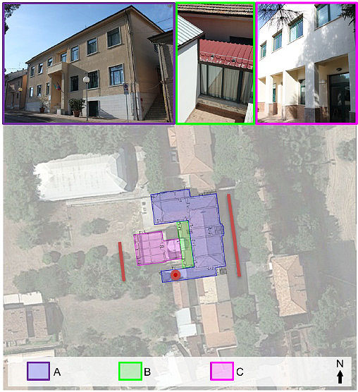
The Primary and Lower Secondary School “G. Marconi” of Monterado described in Fig. (2) is located in the municipality of Trecastelli (AN). The school complex consists of three independent buildings of different structural and material types: the first construction was built with masonry walls and one-way hollow block slabs (Unit A in Fig. (2); the second part is one-storey RC building added to the first construction to optimise the school activities (Unit B in Fig. (2) and the third building is two-storeys RC framed structure recently built as an extension for teaching purposes (Unit C in Fig. (2).
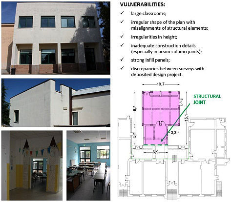
For the sake of brevity, only the analyses carried out for Unit C are reported. Building C Fig. (3) is characterised by a plan consisting of two misaligned rectangles, with the dimensions of 10.7 m x 9.7 m and 6.9 m x 5.4 m, respectively, made up of RC framed structure with columns (arranged with distances from 2.65 m to 3.92 m in X-direction and 3.85 m and 4.80 m in Y-direction) and beams.
The intermediate floor and the roof are cast-in-place one-way hollow block slabs with a thickness of 20 + 4 cm and 16 + 4 cm with RC joists (i = 50 cm) and they are considered (for their characteristics) as “rigid floor diaphragms.”Infill walls are made from double layer hollow blocks, mortar, insulation and plaster. This building is structurally independent of the others, thus the seismic vulnerability of this structure, without interactions, is evaluated with different approaches reported in Section 3.
| School ID | Level of Education | Structures of Each Complex | Years of Construction | Trecastelli’s Hamlet | Altitude Above Sea Level (m a.s.l.) | Soil/Subsoil Type |
|---|---|---|---|---|---|---|
| 1 | Lower Secondary School | Four RC buildings | 1970 - 1980 | Ripe | 120-140 | C T3 |
| 2 | Primary School and Lower Secondary School | One masonry building Two RC buildings |
1930 - 2008 | Monterado | 163 | C T3 |
| 3 | Kindergarten School | Two RC buildings | 1971 - 2011 | Ripe | 48 | C T1 |
| 4 | Kindergarten School | One masonry building Three RC buildings |
Before 1967 - 1992 | Castel Colonna | 150 | B T3 |
| 5 | Kindergarten School | One RC building | 1992 | Ripe | 130 | C T1 |
| 6 | Kindergarten School | Four RC buildings | 1983 - 2009 | Monterado | 39 | C T1 |
| School ID | Building ID | Number of Storeys | ~ m2 | CF | Min IR |
|---|---|---|---|---|---|
| 1 | A | 1 | 500 | 1.2 | 0.13 |
| B | 1 | 215 | 1 | 0.23 | |
| C | 2 | 245 | 1 | 0.21 | |
| D | 4+1 only for stairs | 625 | 1.2 | 0.13 | |
| 2 | A | 2 + 1 for the garret | 795 | 1.2 | 0.54 |
| B | 1 | 100 | 1 | 0.41 | |
| C | 2 | 220 | 1 | 0.23 | |
| 3 | A | 1 | 530 | 1.2 | 0.17 |
| B | 1 | 85 | 1.2 | 0.45 | |
| 4 | A | 2 | 300 | 1.2 | 0.90 |
| B | 1 | 35 | 1.2 | 0.21 | |
| C | 2 | 95 | 1.2 | 0.23 | |
| D | 2 | 30 | 1.2 | 0.23 | |
| 5 | A | 1 | 420 | 1.2 | 0.17 |
| 6 | A | 1 | 600 | 1.2 | 0.23 |
| B | 1 | 30 | 1.2 | 0.70 | |
| C | 1 | 145 | 1.2 | 0.48 | |
| D | 1 | 100 | 1.2 | 0.45 |
2.4. Acquisition of the Appropriate KL of the Building and Material Properties
Regarding the seismic assessment of existing RC buildings, accurate estimations of the concrete and reinforcement mechanical properties are fundamental tasks to provide a reliable prediction of their seismic behaviour.
The compressive strength of concrete is the most commonly used parameter to characterise concrete mechanical properties, directly connected to Young’s modulus. Carbonation tests can be added to assess the state of degradation of structural elements.
The concrete core testing used in this work is a destructive test that consists of the extraction of concrete cores from structural elements and the execution of compression tests in the laboratory, as one of the most reliable tools to capture the properties of concrete.
The available data obtained by surveys achieve a full Knowledge Level (KL), classified in the European Standard EC8 [20] and the Italian Seismic Code (NTC2018) [18] as KL3, corresponding to a Confidence Factor (CF) equal to 1.00.
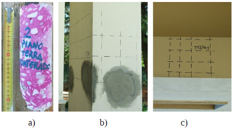
Concrete core testing and carbonation testing (Fig. 4a) carried out on the main structural elements show good properties of the concrete without degradation or decay and covemeter tests confirm the rebar spacing as designed (Fig. 4b-c). The values of material properties, used for nonlinear analyses derived from destructive tests previously described, are the mean value of in situ concrete strength fcm=34.58 MPa, Young’s modulus of 31920 MPa and the mean value of in situ steel yielding of reinforcement bars fym=543.49 MPa.
3. NUMERICAL MODELLING
3.1. Seismic Performance Evaluation
The global seismic analysis uses methods of analysis that allow evaluating the possibility of developing resistant mechanisms both “ductile” and “brittle” and adopting material parameters diversified according to the type of verification. National [13, 19] and International [20] Codes or Guidelines [21] point out that in the existing structures the capacity of elements, with both “ductile” and “brittle” resistant mechanisms could occur.
The analysis of structures subject to seismic action can be linear or nonlinear. The nonlinear static (pushover) analysis was developed over the last two decades, and it became the most suitable procedure to design and evaluate the seismic performance of buildings.
The derivation of the capacity curves for RC structures requires a certain computational effort. It also needs a careful - and demanding - check of the input data, since the results are susceptible to the geometric and material modelling, in particular with strong irregularities in plan and height [22].
The nonlinear static analysis is performed following the N2 method, originally proposed in [23], with two distributions, one is proportional to the fundamental mode and the other to the mass. In the following, the two distributions will be identified with the labels “PushMode” (proportional to the mode) and “PushMass” (proportional to the mass).
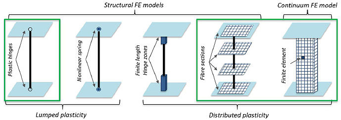
The main modelling strategies to assess the nonlinear building response, available in common computational codes, follow the lumped and the distributed plasticity approaches and numerical FE models of RC structures herein consisting of beam elements or 3D finite elements (Fig. 5).
In the following paragraphs, the descriptions of the three models of the case study, made with different modelling approaches, are reported to evaluate the incidence of FE modelling type on the representation of the effects induced by vulnerabilities and to consider additional information provided by a more refined modelling approach.
3.2. Lumped Plasticity Model (LPM) - Plastic Hinges
Lumped Plasticity Models (LPM) are usually associated with a phenomenological approach where the dissipation areas are, typically, located at the end of the element, and usually synthesised by a hysteretic behaviour, which differs according to the axial (N) - bending (M) - shear (V) failure.
Advantages of this modelling are: 1) low computational cost; 2) the capacity to depict nonlinear phenomena such as buckling of rebars, bond slip between bars and concrete, poor confinement and shear deformability; 3) the correspondence to the reality as long as there are no specific situations considering chord rotations of main elements calculated with trinomial formulation (e.g., sections must be rectangular in shape).
On the other hand, the choice to locate the plastic hinges requires a specific experience of the operator, as well as the shear span definition and the force-deformation relationship assigned to them [22]. The main problem is the absence of interaction between axial, bending and shear forces during the transversal loading increment that it is purely numerical and delegated to the FE solver.
Furthermore, these quantities are a function of the shear span, which is always constant during the loading increment: this assumption can lead to under- or over-estimate the capacity of the element. This means that the capacity curve is not enough to evaluate the structure capacity, without local checks. With the lumped plasticity approach, more sophisticated models could be considered such as [24], which takes into account axial force, bending and shear behaviours and their interactions by a single plastic hinge.
The frame structure is modelled by beam elements (Fig. 6a) and the infinite in-plane stiffness of the floors is considered.
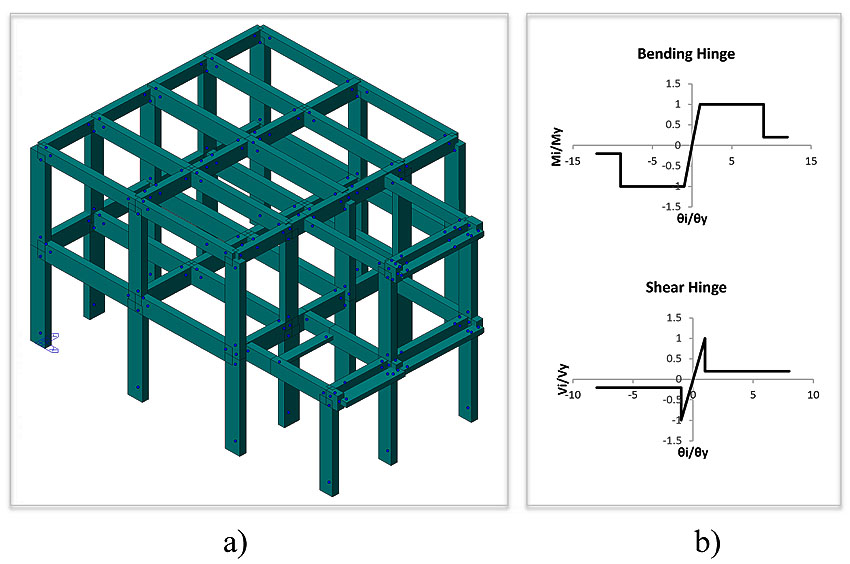
The classic parabola-rectangle diagram for the concrete under compression is implemented along with an elastic-hardening diagram for the reinforcement steel. As already mentioned, in order to describe the nonlinear behaviour of columns and beams, a lumped plasticity approach is adopted with default plastic hinges assigned to the elements: axial force and biaxial bending interaction (i.e., PMM 3D status determination which takes into account the variation of axial force during the analysis) for columns, and pure bending (i.e., M3 pure uniaxial bending) for beams. The hinge nonlinear constitutive laws suggested by the Eurocode 8 provisions [20] mentioned above Fig. (6b) are applied.
According to Eurocode 8 and Italian Seismic Code, the beam and column verifications for the LSSD (Limit State of Significant Damage) consist of checking if the structure could achieve the displacement demand without the elements reaching their ultimate deformation (ductile mechanism). The check is satisfied if θD≤θC, where θC is the chord rotation capacity, which for LSSD is equal to ¾θu [18], θD is the chord rotation demand and θU is the ultimate chord rotation.
Given that existing RC buildings usually have an insufficient amount of transverse steel reinforcement (stirrups), the shear failure of members is considered in the model by the introduction of shear hinges (Fig. 6b) [26].
The brittle mechanisms are evaluated through the shear demand and corresponding capacity at the two ends of each structural member. The procedure to assess the shear capacity, based on the resisting model of the classical Mörsch-Ritter truss, is proposed in Italian Seismic Code [18] (same as Eurocode 2), and differs from those recommended in Eurocode 8 [20] and CNR-DT 212 [15].
Finally, the capacity evaluation of beam-column joints must be carried out. The Italian Code [18] deals separately with joints belonging to new or existing buildings, unlike the EC8.
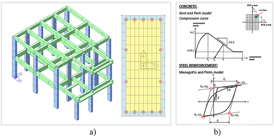
3.3. Distributed Plasticity Model - Fibre Model (FM)
In this model, the plasticity is distributed throughout any structural element, both transversely and longitudinally. Elements are discretised in “control sections” with a considerable number of fibres (Fig. 7a) which only deform axially, using a force-based element formulation [25].
The Fibre Model (FM) considers the distributed nonlinearity unlike the lumped plasticity model; the nonlinearity of the material allows to derive the behaviour of the element through an integration of the response in the section. Therefore, for each change in cross section of geometry or reinforcement, a different fibre section must be assigned.
A fibre model accurately describes the interaction between the axial force and the two components of bending moment. Primarily, it has the advantage of considering the movement of neutral axis due to the axial force. The model consists of the same geometries as in the previous lumped plasticity model, with the same loads and assigned constraint conditions. It does not require a great experience of the operator since plasticization can occur anywhere into the element. If the number of fibres is sufficiently high, the distribution of the mechanical nonlinearities, due to the materials on the surface of the section, is accurately modelled.
Actually, in commercial codes, a FM is not suitable to represent nonlinear phenomena such as the buckling of rebars, bond-slip between bars and concrete and shear failure, etc. Therefore, the FM is unsuitable for structures characterised by shear failures.
A distributed plasticity approach - less constrained to initial assumptions - suffers the absence of an interaction between bending (M), shear (V) and axial force (N) as the lumped plasticity approach, and it is an extremely time-consuming calculation.
The nonlinear properties of sections follow the stress-strain relationship proposed in literature, based on experimental tests, for the behaviour of concrete subjected to cyclic loads [27]. In particular, for this case study, the Kent and Park model [28] is used for concrete, which is refined to take into account the lateral confinement contribution of stirrups. Tension strength of concrete is ignored. The nonlinear behaviour of steel is represented by Menegotto and Pinto model, modified by Filippou et al. [29].
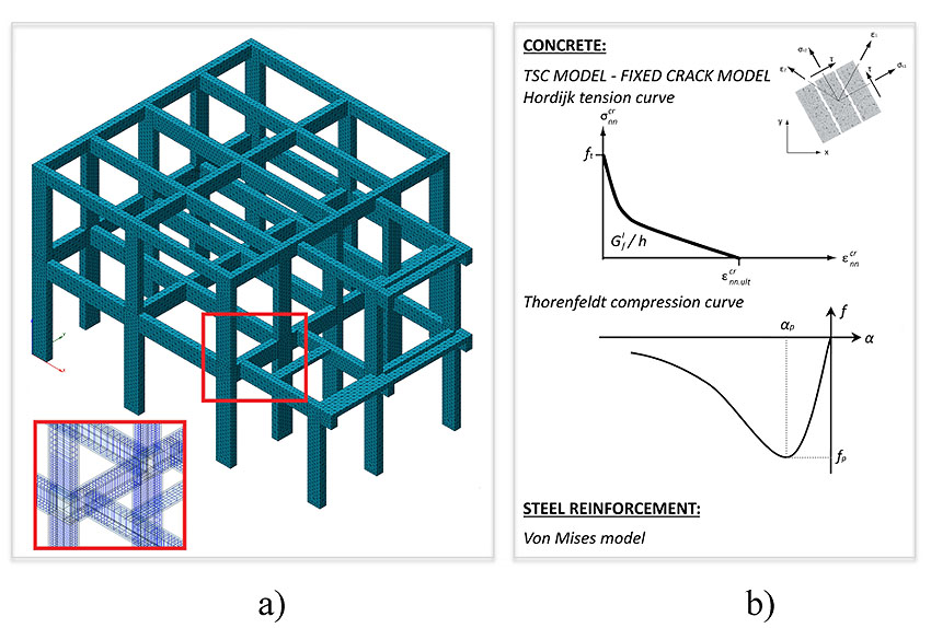
3.4. 3D Continuum FE Model (CM) Using a Smeared Approach for the Fracture Energy
The proposed numerical model to study the in-plane behaviour of concrete elements is based on a smeared crack approach, where the concrete cracks are assumed to be scattered and distributed, but not directly modelled. Since smeared crack modelling approaches do not require re-meshing of the Finite Element (FE) model after the occurrence of cracks or a priori definition of possible locations of cracks, they are widely used in FE modelling. The smeared crack models are practice-oriented due to less required data. Continuum FE models (CM) are used not only for RC structures - as in this case - but also for masonry structures [30-32].
The application of computationally expensive 3D continuum FE models will be of interest for the design of large-scale tests in earthquake engineering [33].
The smeared crack concept itself offers a variety of possibilities, ranging from fixed single to fixed multi-directional and rotating crack approaches. Here, the distinction lies in the orientation of the crack, which is either kept constant, updated in a stepwise manner, or updated continuously. The Total Strain Crack Model is chosen, with a fixed crack model, to accurately simulate the physical behaviours of concrete cracks for the case study.
The total strain model in the smeared crack model can be rather simply formulated using total strain without having to decompose it into the strain components. Also, its algorithm is easy to understand because the total strain model uses only one stress-strain relationship for tensile behaviour, including cracks and one for compressive behaviour.
The numerical model is built to reproduce the geometry of the structure, using 3D mesh elements for the concrete and 1D mesh elements for embedded bars. The adopted mesh size is 150 mm. The hypothesis of rigid floor slab is used, since it is close to the reality, with fixed constraints on the ground floor. After meshing, the CM is reported in Fig. (8a). The number of elements created is 86824 with 88968 degrees of freedom (d.o.f.).
The constitutive models, selected for concrete tensile and compressive behaviours are, respectively, the nonlinear tension softening of Hordijk model and the compression curve of Thorenfeldt model Fig. (8b).
|
Mode No. |
Period | Frequency | TRAN-X | TRAN-Y | ROTN-Z | ||||
|---|---|---|---|---|---|---|---|---|---|
| (sec) | (rad/sec) | (cycle/sec) | Mass(%) | Sum(%) | Mass(%) | Sum(%) | Mass(%) | Sum(%) | |
| 1 | 0.1931 | 32.5311 | 5.1775 | 0.0252 | 0.0252 | 87.9586 | 87.9586 | 1.4581 | 1.4581 |
| 2 | 0.1753 | 35.8417 | 5.7044 | 84.666 | 84.6912 | 0.072 | 88.0306 | 0.7561 | 2.2142 |
| 3 | 0.1515 | 41.4676 | 6.5998 | 0.7099 | 85.401 | 1.3849 | 89.4155 | 85.2355 | 87.4497 |
| 4 | 0.0808 | 77.7542 | 12.375 | 0.0023 | 85.4034 | 10.1844 | 99.5999 | 0.3842 | 87.8339 |
| 5 | 0.0642 | 97.7963 | 15.5648 | 13.8341 | 99.2375 | 0.0326 | 99.6325 | 0.8006 | 88.6345 |
| 6 | 0.0616 | 102.0763 | 16.246 | 0.7625 | 100 | 0.3675 | 100 | 11.3655 | 100 |
|
Mode No. |
Period | Frequency | TRAN-X | TRAN-Y | ROTN-Z | ||||
|---|---|---|---|---|---|---|---|---|---|
| (sec) | (rad/sec) | (cycle/sec) | Mass(%) | Sum(%) | Mass(%) | Sum(%) | Mass(%) | Sum(%) | |
| 1 | 0.1922 | 32.6958 | 5.2037 | 0.0192 | 0.0192 | 86.9859 | 86.9859 | 1.016 | 1.016 |
| 2 | 0.1744 | 36.0366 | 5.7354 | 83.486 | 83.5052 | 0.0462 | 87.0321 | 0.5297 | 1.5457 |
| 3 | 0.1454 | 43.2141 | 6.8777 | 0.4821 | 83.9872 | 0.9682 | 88.0003 | 84.0944 | 85.6401 |
| 4 | 0.079 | 79.4977 | 12.6525 | 0.0018 | 83.989 | 10.2112 | 98.2116 | 0.2655 | 85.9056 |
| 5 | 0.0629 | 99.8996 | 15.8995 | 14.1977 | 98.1868 | 0.0094 | 98.2209 | 0.2482 | 86.1537 |
| 6 | 0.0581 | 108.1769 | 17.2169 | 0.1957 | 98.3825 | 0.2945 | 98.5154 | 11.7349 | 97.8887 |
Moreover, the modelling of shear behaviour is necessary for the fixed crack concept, where the shear stiffness is usually reduced after cracking with a classical constant value.
The lateral crack and the confinement effects are considered by the formulation of Vecchio and Collins [34] and Selby and Vecchio [35]. The required concrete material properties to analyse crack models are defined using CEB-FIP 1990 [36]. The value of fracture energy (Gf) considered is equal to 0.072 N/mm. The constitutive law for steel reinforcements is selected according to Von Mises’ model.
The concrete and steel reinforcement parameters used for the case study are previously summarised in Section 2.
The nonlinear system of equations is solved by an incremental nonlinear static analysis using the Arc-length iteration procedure with the Initial Stiffness Method and requested energy norm with 10-2 tolerance. It is noteworthy to point out that the computation, required by each pushover analysis, is time-consuming.
4. RESULTS
4.1. Modal Analyses
The three different models, previously described in Section 3, are used to assess the dynamic characteristics of the structure through modal analyses.
The natural periods with the corresponding participation masses are reported in Table 3 for the LPM, in Table 4 for the FM and in Table 5 for the CM.
From all FE models, the same 1st and 2nd vibration modes are detected. As expected, the modal participation masses of the first modes are higher than 75% in both directions (due to the assumption of rigid floors).
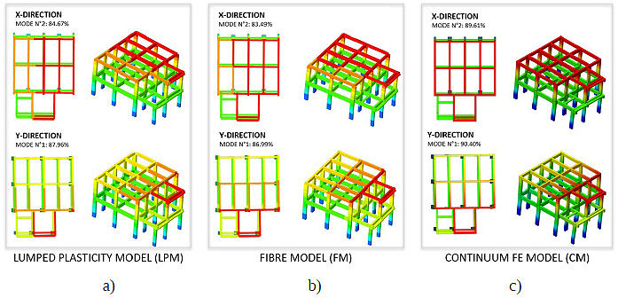
The results of modal analyses for the three models are shown in Fig. (9) for a) LPM, b) FM and c) CM models. The differences between outputs are due to the contribution of the embedded bars in the stiffness of elements.
In both directions, a perfect correlation between the mode shapes of the different models is visible. The CM also shows a slight increase in participating mass compared to the other two types of models.
4.2. Nonlinear Static Analyses
The pushover curves obtained with the Italian Seismic Code formulation are reported in Fig. (10) with: dashed lines for the PushMode and PushMass distributions of the LPM; dotted lines for the FM and continuous lines for the CM in each direction.
The capacity curves highlight a brittle global behaviour (i.e., where the vertical drop in the capacity curve is visible), mainly in -Y/+Y directions. Low building performances are caused by brittle mechanisms, localised on the first-floor beams, with misalignments of structural elements.
To summarise the seismic performances of the school, according to the lumped plasticity model used for its description, the global seismic risk index corresponds to a drop of the base shear, at least, for about 15%, concerning the maximum value of IR=0.53 (TR=150 years).
Comparing this result with the safety verifications of brittle members, in terms of IR, the global mechanism is gained immediately after the local failure for the brittle mechanism (IR=0.51, TR=140 years).
As regards to the prediction of the beam-column joint behaviour, by using expressions reported in the Italian Code [18], the failure of more than 20 joints out of 28 occured for IR=0.23 (TR=20 years).
The consistency of the results obtained with the LPM is checked by comparison with the pushover curves of the other models (Fig. 10).
Regarding the global behaviour, the initial elastic stiffness of the capacity curves both for the LPM and the CM, is markedly different compared to the corresponding FM curves.
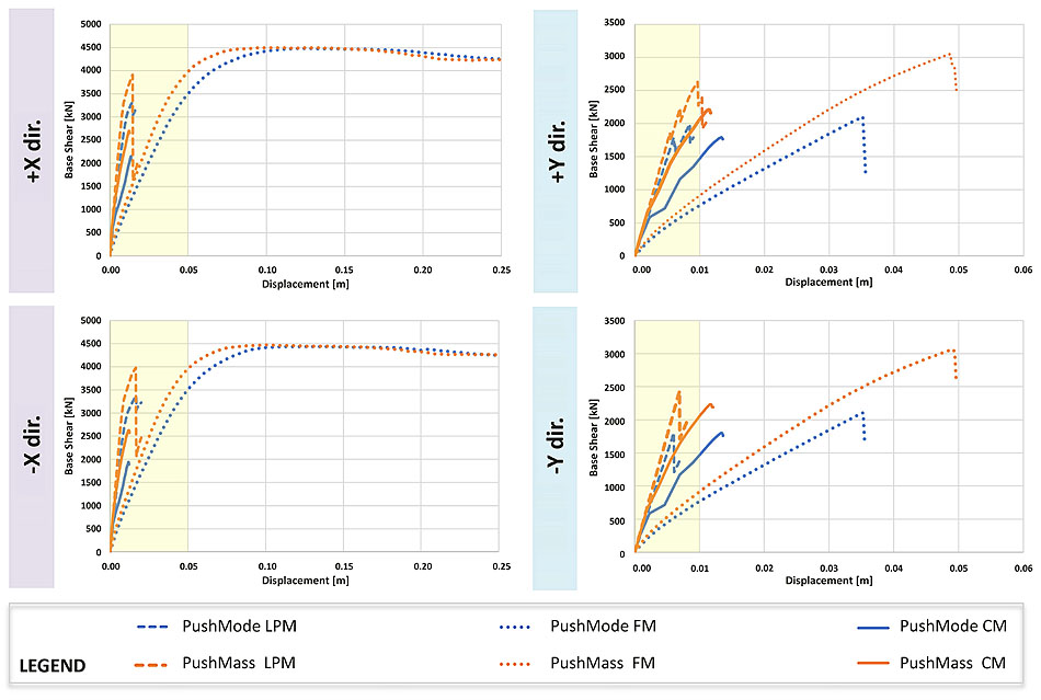
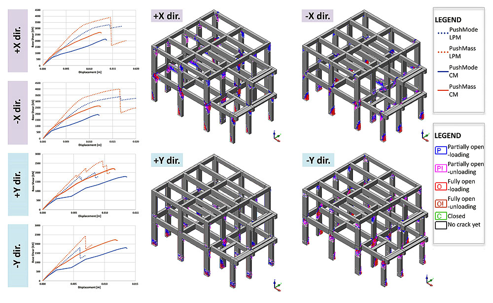
Table 5.
|
Mode No. |
Period | Frequency | TRAN-X | TRAN-Y | ROTN-Z | ||||
|---|---|---|---|---|---|---|---|---|---|
| [sec] | [rad/sec] | [cycle/sec] | Mass(%) | Sum(%) | Mass(%) | Sum(%) | Mass(%) | Sum(%) | |
| 1 | 0.17898 | 35.10545 | 5.587206 | 0.02 | 0.02 | 90.4 | 90.4 | 2.35 | 2.35 |
| 2 | 0.154355 | 40.70601 | 6.478562 | 89.61 | 89.63 | 0.01 | 90.41 | 0.01 | 2.35 |
| 3 | 0.136624 | 45.989 | 7.319376 | 0.02 | 89.65 | 0.84 | 91.25 | 61.79 | 64.14 |
| 4 | 0.07162 | 87.72921 | 13.96254 | 0 | 89.65 | 5.13 | 96.38 | 0.25 | 64.39 |
| 5 | 0.060687 | 103.534 | 16.47794 | 6.85 | 96.5 | 0.04 | 96.42 | 0.33 | 64.73 |
| 6 | 0.053811 | 116.7645 | 18.58365 | 0.41 | 96.91 | 0.61 | 97.04 | 4.14 | 68.87 |
The stiffness is influenced by choice of the plastic hinge type and location: a stiffer behaviour is observed if the plastic behaviour is lumped at the end of the element, as in the LPM, compared to the FM [37].
The concomitance of bending (M), shear (V) and axial force (N), and the interaction between them in the inelastic response represent the most relevant phenomena treated approximately and incompletely both LPM and FM. Otherwise, through the continuum model, it is possible to evaluate together the states of stress (axial bending and shear), offering a realistic representation of the phenomena, as well as stresses on the beam-column joints. Fig. (11) shows the comparison between the CM with the LPM.
The displacements are less in the worst (+ /-Y) directions, and very limited in the LPM model, but they increase in the CM model. Also, it is possible to observe the variation of the slope of the CM capacity curves, after the first initial elastic part overlapped on the LPM curves.
Fig. (11) also shows the cracking pattern that spreads mainly on the beam-column joints, which are the most stressed elements together with the base of the columns.
A reliable evaluation of strength and deformability of beam-column joints is a crucial aspect in the framework of performance-based design or evaluation of Reinforced Concrete (RC) buildings, as confirmed by recent experimental activities and damage observations from recent earthquakes [38].
In literature, the behaviour of wide beam-column joints has been evaluated using both experimental tests under cyclic loading and accurate nonlinear finite element analyses with a satisfactory prediction of experimental results [39].
As shown by many experimental programs, the failure of beam-column joints is induced usually by shear. The stress distribution due to flexural and shear forces transferred through the joint produces a wide diagonal crack pattern in the panel leading to a crushing failure of the compressed strut and consequently to strength and stiffness deterioration.
The cyclic deterioration of bond performance of steel reinforcements, on one side, yields to reduced flexural strength and ductility of framing elements on yield, and on the other side, to a noticeable increase in the story drift.
In the case study, most of the joints subject to failure identified in the LPM confirm the damage in the CM; in other cases, the simplified LPM tends to be too restrictive.
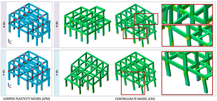
In Fig. (12), 3D element strains for CM for -X and -Y directions are shown: shear cracks with the diagonal pattern are visible, while in other joints there are mechanisms of a different nature not attributable to a well-defined type of failure.
Nowadays, a large consensus has not been found on a single joint modelling technique neither in the scientific literature nor in Codes, although many research groups worldwide, during the last three decades, performed wide experimental and theoretical studies on this topic, to evaluate the behaviour of beam-column joints [40, 41].
Due to the limited number of tests available, refined numerical simulations are required to get a reliable proof of the effectiveness of code expressions. In this context, with a continuum approach, the approximations (e.g. geometric) are limited. It should be noted that, even if the structure is simple (with some negligible irregularities), probably, there will not be a type of mechanism that can be ascribed only to bending or shear behaviour. Of course, the information given by the continuum model is more accurate than other modelling approaches, to represent the complex and combined mechanisms developed in joints.
5. FRP LOCAL RETROFIT STRENGTHENING OF RC BEAM-COLUMN JOINTS
The recent seismic events demonstrate that the high vulnerability of existing RC structures is often related to the joint shear failure, which may lead to the collapse of the entire building. Joints damage and a great demand of ductility in the columns are usually located in the external joints and columns, for several reasons: (i) they are not confined at least on one or two sides; (ii) joints and columns are subjected to the infill strut force which is not compensated by another wall in the opposite side; and finally the structural elements may be subject to large deformations due to torsional effects that can occur on the structure. However, most of the available computer software does not properly account the above-mentioned aspects. Some experimental tests and numerical simulations of unreinforced external RC beam-column joints are performed by [42-44].
For RC buildings, the recent Guidelines for the classification of seismic risk of constructions in Annex A of M.D. 65 7-3-2017, which modifies M.D. 58 28-2-2017 “Sismabonus” Decree [45, 46] allow to switch to the next, higher Class of Seismic Risk for a construction performing only local strengthening interventions and also in the absence of a prior attribution of the Class of Risk.
This is only possible if the structure was originally conceived with RC frames in both directions and if all the following interventions are carried out: (i) the confinement of all the unconfined peripheral panel joints of the building, (ii) the prevention of the overturning of the peripheral infill panels and the restoration of damaged and/or deteriorated areas.
The Guidelines for repairing and strengthening of structural elements, infill walls and partitions [47] developed by the ReLUIS Consortium and the Civil Protection Department, in agreement with interventions foreseen in the OPCM 3779 [48], recommend the definition of local interventions to confine all the unconfined peripheral joints. Local interventions have to be used with the most appropriate techniques to the case study, under the economic and technological aspects and with reference to the geometric characteristics of the elements to be reinforced and the interaction with the overall structure.
Focusing on the unconfined beam-column joints, among the possible techniques that can be chosen to reinforce them, the most widespread solutions (also analysed by the Guidelines [47]) are based on: steel jacketing [49]; plating [50] or wrapping with composite materials [51, 52]; or CAM® jacketing [53]. Fibre Reinforced Polymer (FRP) systems are known for their light weight, durability and easy installation. Many experimental tests and analytical studies pointed out the effectiveness of FRP strengthening systems that improve the global seismic capacity [54].
A correct design of FRP intervention should be implemented according to the CNR-DT200 [55] and the Guidelines of the Supreme Council of Public Works [56]. The intervention is useful only if the ends of the strengthening are properly anchored with FRP anchors; otherwise, reinforcement cannot be considered effective.
The predicted structural performances and structural damage observable before and after the retrofit intervention are compared and the benefits of FRP strengthening on the overall structure behaviour are assessed.
5.1. A Numerical Model of the School Building with FRP Strengthening
The starting numerical model of the structure built using the software Midas FEA [57] is the same as one shown in Section 3, with the nonlinear behaviour reported in Fig. (8).
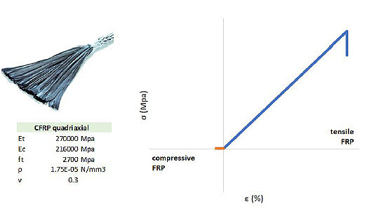
The increase of the shear capacity of each beam-column joint can be achieved through the application of composites with fibres placed along the axes of principal tensile stresses. For this case study, two crossed quadriaxial CFRP sheets with unit weight of 1.75 g/cm3, thickness of dry fibre of 0.106 mm, Young modulus of 270GPa (Fig. 13) are adopted for joint strengthening and anchored by FRP anchors to delay the premature FRP debonding.
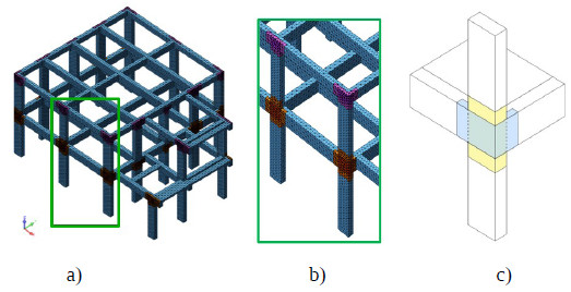
These sheets are externally bonded on the joint panel with fibres in the directions of 0°, ±45° and 90° in respect to the beam axis, and they are modelled using 3D solid elements directly connected to the nodes of the concrete meshes, without using interface elements between the FRP and the concrete support (Fig. 14 a,b and c).
Thus, perfect adhesion between concrete joint and FRP is considered: this assumption reflects the use of proper anchorage solution in Fibre-Reinforced Polymer (FRP) composites to delay the premature FRP debonding and enhance the deformability of FRP-to-concrete interfaces (FRP debonding and FRP tension rupture are identified as two main failure modes of FRP: with the use of proper anchorage solution only FRP tension rupture may occur).
CFRP sheets are considered unable to carry compression loads (compressive strength almost zero), and the tensile behaviour is represented with a stress-strain relationship reported in Fig. (13). The intervention is conceived as less invasive as possible and only to confine the unconfined joint panel, to understand if the FRP strengthening could modify the transverse stiffness and overall structure behaviour compared to the case without FRP.
The realistic representation of this intervention can only be achieved with refined models (Fig. 14a, b), because with classical approaches the joint is considered over-resistant in respect to beams and columns.
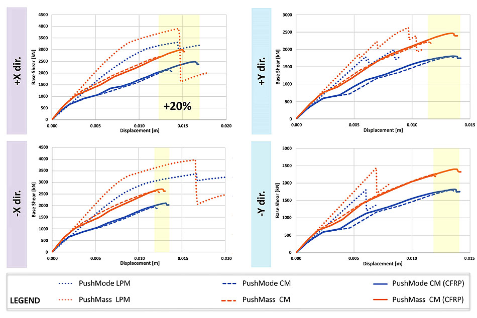
The comparisons, in terms of pushover curves, are reported in Fig. (15), highlighting that the FRP strengthening improves the displacement capacity of the structure. Moreover, the initial stiffness does not change substantially for any direction analysed.
For +X direction, the intervention increases the displacement capacity of the structure of about 20% with both PushMode and PushMass analyses. For the other directions, the increase varies from 5 to 20%. The use of FRP sheets bonded on the exterior surface of beam-column joints may improve the seismic performances (i.e., providing stabilization of the structural response) of frames without significant change of the stiffness of the structure.
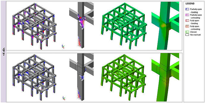
The local strengthening of beam-column joints prevents the shear failure promoting a ductile failure mode with a higher displacement capacity and higher seismic performances than the unreinforced case. Indeed, Fig. (16) points out significant damage on beams and columns instead of joint shear cracks.
CONCLUSION AND FUTURE WORKS
This work investigates the influence of FE modelling on typical and specific vulnerabilities of school buildings belonging to the lower levels of the Italian education system.
To evaluate the effects due to irregularities, layout plan and inadequate construction details, a case study is examined thoroughly that considers additional information provided by more accurate modelling approaches (where the mechanical nonlinearities are accurately represented) than a simpler one. Three different models are implemented with various limitations to represent the reality.
First of all, this study has highlighted the strengths and weaknesses of different modelling types and the numerical error introduced using LPM. Although in previous works it was shown the possibility to use more sophisticated models [24] to consider N-M-V forces and their interactions by a single plastic hinge, this study confirms the unpredictability of the behaviour of joints, supposed to be over-resistant compared to the structural elements, and how they affect overall behaviour.
It is also an extension of previous works related to the vulnerability assessment of school buildings [6] with important improvements from the point of view of refined modelling types adopted. Also, in the above-mentioned work, it is emphasized that joint failure is not considered.
In the selected case study, shear is the most critical action for the analysed building. The concomitance of bending, shear, and axial force and their interaction in the inelastic response are the most relevant problems treated in an approximate and incomplete way by both the LPM and FM.
In literature, to the best knowledge of the authors, studies related to beam-column joints have been carried out almost exclusively on limited parts of structural systems, at most composed of only a frame.
Through CM is possible to evaluate together the states of stress, instead offering their realistic representation in the beam-column joints. The FM without elements to account the shear behaviour is not suitable for structures characterised by shear failure neither for representing nonlinear phenomena, such as the buckling of rebars, bond-slip between bars and concrete, and shear failure.
Nonlinear static analyses are performed by following the N2 method with two distributions, one proportional to the fundamental mode and the other to the mass. The comparison of pushover curves confirms greater displacement capacities in the CM compared to the LPM in the worst directions (+Y/-Y).
Most of the damaged joints identified in the LP model confirms their failure in CM, in some cases, the LP model is too much restrictive. The information about the mechanisms developed in joints given by the CM is more meaningful than that offered by simple models, and useful to identify shortcomings of the design project for strengthening interventions.
The repetitiveness of collapse mechanisms requires interventions to reduce or eliminate the original shortcomings of the design project, e.g., reducing the weakness of beam-column joints.
After the assessment of the vulnerabilities and the identification of the deficiencies, the definition of local interventions is carried out with the CFRP strengthening system using a 3D Continuum FE model, to take into account the joint nonlinear behaviour and the Fibre Reinforced Polymer (FRP) strengthening in the Finite Element method (FEM).
The intervention is conceived as less invasive as possible and only to confine the unconfined joint panel, with the idea of understanding if the FRP strengthening could modify the transverse stiffness and overall structure behaviour, compared to the case without FRP.
In conclusion, CFRP sheets externally bonded on beam-column joints may improve the seismic frame performances without a significant change in the stiffness of the structure, promoting a more ductile failure mode with a higher displacement capacity than the unreinforced case.
The comparison between the three different types of modelling should also be extended on future works to structures subject to shear actions, i.e., built before 1974, characterised by the lack of any design rule attributable to the capacity design, considering that the case study analysed in detail in Section 2.3 is designed with a more advanced code.
These evaluations could be performed by considering further FRP strengthening configurations and alternative intervention techniques such as steel jacketing, plating and CAM® jacketing.
CONSENT FOR PUBLICATION
Not applicable.
AVAILABILITY OF DATA AND MATERIALS
The data that support the findings of this study are available from the corresponding author upon request.
FUNDING
None.
CONFLICT OF INTEREST
The authors declare no conflict of interest, financial or otherwise.
ACKNOWLEDGEMENTS
The authors wish to thank the municipality of Trecastelli together with Arch. Stefano Ciarloni for the useful aid in the preliminary developments of this research.

