All published articles of this journal are available on ScienceDirect.

Efficiency of Stress-Strain Models of Confined Concrete With and Without Steel Jacketing to Reproduce Experimental Results
Abstract
The improvement and the capacity assessment of existing buildings has become the main topic of the last years so that different studies can be found devoted to damaged structures or structures not having a capacity compatible with the safety levels of the actual codes. Reinforced concrete framed structure buildings represent a conspicuous rate of the existing constructions so many efforts are addressed to them. Referring to this type of buildings, a good prediction of strength and deformation capacity requests models able to interpret the constitutive law of concrete confined by internal reinforcement or by eventual external reinforcement applied to increase capacity of cross-sections. Considering that one of the techniques much diffused for the improvement of the capacity of reinforced concrete members is the steel jacketing by the combined system of angles and battens, models able to predict the real contribution of this kind of intervention are desirable. In this connection the paper discusses the different confined concrete models available in the literature, analyzing all the characteristics and comparing the σ-ε constitutive laws for different type of RC cross sections. Also, an experimental campaign aimed to the validation of the above models is presented. Through the paper, the results of tests on columns reinforced with steel jacketing are described and the reliability of some costitutive laws for concrete confined by steel jacketing is examined.
1. INTRODUCTION
Identification of the behavior of reinforced concrete (RC) cross-sections in terms of relation between bending moment and curvature is basic for a reliable seismic capacity assessment of reinforced concrete framed structures. The capacity is evaluated by taking into account the behaviour of concrete in compression by proper stress-strain law.
Several experimental studies were devoted to the identification of analytical stress-strain laws for confined concrete in normal members or in members externally strengthened by steel angles and battens. In each of the two cases, concrete σ-ε laws appear different from each other hence assigning a level of reliability to these laws and giving an address, about which the most appropriate are, is necessary for the practical applications.
In the context of the rehabilitation of reinforced concrete framed structure, the further contribution to confinement given by steel jacketing has become more and more interesting. Steel jacketing increases cross-section capacity in relation to the geometric configuration and resistance of steel elements. In the most diffused cases in which steel jacketing is constituted by angles and battens, the latter contrasts the expansion of concrete core during the compression of members producing also abenefitfor longitudinal rebars in terms of prevention of post yield buckling. Then, angles increase the flexural strength and ductility.
As in the case of the ordinary reinforcement, different models were formulated for the confinement effect of steel jacketing with angles and battens whose reliability is discussed through the paper by a comparison with same experimental results.
In the next sections first the most used ordinary confinement concrete models will be described and compared with the results of an experimental campaign recently carried out. Then referring to columns strengthened by steel jacketing the above models of confined will be discussed and compared with the experimental results of tests carried out on jacketed columns.
2. ORDINARY MODELS FOR CONCRETE CONFINED BY STEEL BARS
2.1. State of the Art
The first studies about the behavior of concrete in compression are due to Richart et al. [1]. Their research on confinement action in concrete cylinders, generated by a uniform hydrostatic pressure or steel spirals, forms the basis for the numerous analytical models formulated until today. Among them those of Chan [2], Roy and Sozen [3], Sargin [4], Kent and Park [5], Vallenas et al. [6], Scott et al. [7] have in common the identification of the key variables in the confinement phenomenon of concrete (geometry of cross section, spacing and diameter of the transversal reinforcement).
Kent and Park [5] suppose that confinement does not modify the strength of concrete but only its deformation characteristics in the post peak strength. The same holds for the strains at the peak strength. In other words the ascending branch of the stress-strain law is not affected by the effect of confinement. In the post-peak branch confinement produces a lower slope of the σ-ε curve compared to unconfined concrete.
The stress-strain law is defined by three branches: the first branch has a parabolic trend up to the peak of the strength, the second branch is linear, while the third branch is horizontal and suggest the residual strength.
Vallenas et al. [6] carried out the study of the confinement under the hypothesis that confinement pressure is exercised by longitudinal and transversal reinforcement, influencing maximum strength and maximum strain of concrete. The strength of confined concrete depends on an increasing factor, while the strain corresponding to the peak of strength is obtained starting from the unconfined strain at the peak of stress and considering a factor depending on the spacing of the stirrups. As Kent-Park model [5] the law is defined by three branches: the difference with the Kent and Park model consists of the level of the residual strength.
In the 1982 Scott et al. [7] starting from the model proposed by Kent and Park [5] introduce the concept of effectively confined area. For the ascending branch (0 ≤ ε ≤ εcc) and for the descending branch (ε > εcc) analytic laws are respectively confirmed. Nevertheless, differently from the Kent and Park model, the strength fcc and the corresponding strain εcc are obtained by multiplying the strength fc and the corresponding strain εc of the unconfined concrete by the increment factor k.
The work of Sheik and Uzumeri [8] is worth considering for the introduction of the concept of "effectively confined concrete core" after the observation of the behavior of columns subjected to axial loads in different configurations of longitudinal or transverse reinforcement.
The model, valid for square sections, is characterized by four branches. The first one includes the strains up to the reaching of the peak of stress (0 < ε < ε ccl) having the same law of the Kent-Park model. The second branch (εcc1 < ε < εcc2) is horizontal. In this range the concrete exhibits a constant strength obtained multiplying the unconfined concrete strength by an increasing factor. The post-peak branch is defined by a linear law, while the stress remains constant in the fourth branch when the value becomes 30% of the maximum.
An important contribute was given by Mander et al. [9], which proposed a generalized model valid for members with circular, square and rectangular cross-sections.
The stress-strain relationship for the confined concrete is a unique analytical law that defines completely the behavior. For rectangular cross-sections the confinement pressure along the two directions x and y, flx and fly, are obtained as a function of the volumetric ratios of transverse reinforcement. Authors consider also a coefficient of area effectively confined ke, depending on the longitudinal, the transversal reinforcement and the spacing of the stirrups in order to obtain the effective lateral pressure fle, x and fle, y. Once the pressures are obtained it is possible to determine the strength increment factor k by an abacus provided by the authors.
Yong et al. [10] were interested in high strength concrete and formulated an empirical model for columns with square cross-section using two relations for stress-strain curves similar to those obtained by Sargin [4]. The law of the confined concrete is characterized by two parabolic branches and a horizontal branch corresponding to a reduction of the strength by 70%.
As usual, the peak of strength of the confined concrete is obtained by a factor that increments the strength of the unconfined concrete. The transverse reinforcement is assumed yielded before peak of resistance is reached.
Saatcioglu and Razvi [11] introduced the concept of “lateral equivalent pressure” distinguishing various configurations of transversal reinforcement for RC. members. This model is based on the hypothesis that the stirrups exert a greater confining pressure at the corners, while its action is lower in the middle zones. The average pressure is not representative of the effective confinement and therefore the effects are overestimated. An equivalent uniform pressure having the same effect of the real distribution is obtained by a reduction coefficient of the average pressure.
The stress-strain law defined by the authors is identified by means of three analytical relations: the first formula define a parabolic branch, starting from zero up to the maximum strength. The second branch is linear until reaching the 20% of the confined strength. After this value, axial strain increase keeping constant the strength.
Cusson and Paultre [12] formulate a model for high strength concrete starting from the model of Richart et al. [1] for the determination of the lateral pressure of the concrete. This pressure is applied in the area effectively confined, defined by Sheik and Uzumeri, [8] that allows to obtain lateral effective pressure. Cusson and Paultre [12] consider that the transverse reinforcement at peak of concrete strength do not reaches the yielding tension, and define an iterative procedure for the determination of the tension in the stirrups.
Kappos and Konstantinidis (1999) [13] realize an empirical model for high strength concrete columns. They started from a previous. model and applied a modification in order to obtain better fitting of the experimental data.
Suzuki et al. [14] formulate a models for square high strength concrete columns. As Cusson and Paultre [12] they consider that the stirrups is not yielded when the concrete reaches the peak of strength and provide an iterative procedure that allows the determination of the tension in the stirrups.
They define two expressions for the stress-strain law of the confined concrete. The first branch is defined by a parabolic relation up to the reaching of the peak of strength and the corresponding axial strain. In the descending branch the law is linear.
Finally the proposal of the actual Eurocode 2 [15] define a stress-strain law for the concrete for the non linear analysis of the structures. The law is defined for the entire strain range. The code do not specify the method for the determination of the confined lateral pressure and the confined concrete strength, in fact the law is applicable for the unconfined and for the confined concrete.
2.2. Comparisons
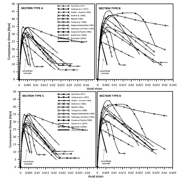
In this subsection the models before described, belonging to the most successful in the literature, are implemented for different geometrical configurations of cross sections. The associated σ-ε curves are plotted for comparison. Four different type of cross-section are used as reported in Table 1. The first type (A) is a square cross-section having medium volumetric steel ratio, while the second type (B) is made of concrete having the same strength assigned to the type A and higher volumetric steel ratio. The third type (C) is a rectangular cross-section having the steel reinforcement assigned to the type A, while the fourth type (D) is a rectangular cross-section having the same steel reinforcement of the type B. The characteristics of the concrete in the last two cases are unchanged.
In order to give an idea about the differences between the curves obtained with the models above described Fig. (2) is provided. This figure shows a deep difference in terms of strength and ductility so high to doubt of the reliability of the models in question. This difference is not justified by the fact that some of them are addressed to high strength concrete and others to normal strength concrete.
Among the models analyzed the one provided by EC2 results the most conservative in terms of ultimate strain. While those of Yong et al. [10] and Kent-Park [5] are the most conservative in terms of strength.
The model of Suzuki et al [14] exhibits a strength twice the amount of the model of Vallenas et al. [6] The ascending branch of the model by Kent and Park [5] is not affected by the effect of confinement, indeed, for both confined concrete and unconfined concrete the σ-ε curves turn out to be the same: in this case transverse reinforcement affects only the ductility of concrete; the modification carried out by Scott et al. [7] concerns the increase of resistance of the confined elements compared to the unconfined ones.
The model of Sheikh and Uzumeri [8] is the only one which presents a horizontal branch, characterized of the maximum strength, between the ascending and descending branches of the stress-strain curve.
It is useful to note that all the models are more influenced by the amount of the steel reinforcement than the geometrical dimensions of the cross-section: keeping the strength of the unconfined concrete and the configuration of reinforcement the model of Young et al. [10] is affected by a small increase of the resistance, the model of Mander et al. [9] moves upwards, Cusson and Paultre [12] model shows slightly increase of resistance and a greater strain at the peak strength, Saatcioglu and Razvi [11] model keeps the ascending branch of the unconfined concrete while the post-peak branch present a lower slope; Vallenas et al. and Scott et al. models are affected by greater strength and strain in correspondence of the peak.
All the models are affected by a greater increase of the strength if steel reinforcement is increased.
Specifically the model that modifies mostly the strength and the axial strain in the post peak branch is that due to Cusson and Paultre [12]
3. MODELS FOR CONCRETE CONFINED BY STEEL JACKETING
Steel jacketing is a good method for repairing or reinforcing existing buildings. It represents an interesting solution for many structural problems. However the knowledge of the behavior of this reinforcing is no satisfactory yet. Surely, data available in the literature show that by using this reinforcing system a good increasing of resistance and ductility is obtained.
The behavior of concrete columns reinforced with steel angles and battens is more complex to describe with respect to the case of unstrengthened columns. The material is featured by different characteristics in a cross-section depending on the distribution of the steel rebars and the external reinforcement. Actually, much effort is devoted to the estimation of the confinement pressure produced by internal and external reinforcement to be used with specific models of confined concrete. For sake of clarity some models for the confinement pressure in question are discussed below. In particular, the models by Braga et al. [16], Montuori and Piluso [17], Nagaprasad et al. [18], Badalamenti et al. [19] are provided.
3.1. Model by Braga et al. (2006) [16]
The model refers to square cross-sections. The key assumption of this model is that the increment of strength of the concrete is not associated to the out-of-plane strain. This means that the confinement exercised by the transverse reinforcement should take place in plane strain condition.
Taking into account the effects of the existing internal stirrups and of the additional external reinforcement separately (principle of effect superposition), the mean confining pressure frm on the concrete core is obtained as:
 |
(1) |
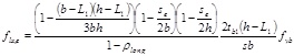
where Acc is the area within the internal stirrups, Ae is the area within the external battens, fe is the confining pressure applied to the core by the internal stirrups and f1,max is the confinement pressure applied by the external reinforcement on the whole section. After a series of passages the authors obtain an explicit expression for the effective confinement pressure on the cross-section as below:
 |
(2) |
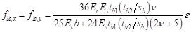
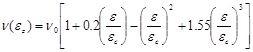
In Eq. (2) b is the square section dimension, Ec the elastic modulus of the concrete, Es the elastic modulus of the steel, tb1 and tb2 the thickness and the width of the battens, sb the spacing of the battens and v the Poisson’s ratio, determined by the following expression:
 |
(3) |
Geometrical scheme of reinforced concrete members.
Main characteristics of the reference cross-sections.
| TYPE | (b x h) (mm) |
(b0 x h0) (mm) |
Cover (c) (mm) |
Stirrup spacing (mm) |
Rebar diameter (mm) |
Volumetric Steel ratio |
fc (MPa) |
fy (MPa) |
|---|---|---|---|---|---|---|---|---|
| A | 200x200 | 162x162 | 15 | 120 | 12 | 0.0259 | 25.00 | 450 |
| B | 200x200 | 162x162 | 15 | 80 | 16 | 0.1072 | 25.00 | 450 |
| C | 320x200 | 262x182 | 15 | 120 | 12 | 0.0142 | 25.00 | 450 |
| D | 320x200 | 262x182 | 15 | 80 | 16 | 0.0590 | 25.00 | 450 |
where v0 = 0.2.
The Poisson’s ratio, coherently with the theory of elasticity, is limited to 0.5, which corresponds to diffuse cracking in the unconfined concrete as experimentally obtained by Kupfer et al. [18].
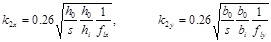
The ultimate strain of confined concrete εccu is fixed by:
 |
(4) |
where pst is the volumetric ratio of transverse reinforcement on concrete core and fyb is the yielding stress of the battens.
3.2. Model by Montuori e Piluso (2009) [17]
The authors defined a relationship for determine the confinement lateral pressure in columns strengthened by internal and external reinforcement. They take into account that in the case of cross sections reinforced by steel angles and battens, concrete is characterized by four different material laws: a) unconfined concrete; concrete confined by internal hoops; concrete confined by steel angles and battens; concrete confined by internal hoops, steel angles and battens. The model proposed for the effective confining pressure resorts the model proposed by Mander et al. [9]
Effects of confinement on stress-strain curve.
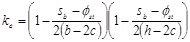
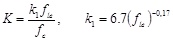
In the case of rectangular cross-sections strengthened by internal hoops and steel angles and battens, the strength increment factor of concrete is evaluated by means of the abacus in Fig. (3) [9] which requires the knowledge of the effective confining pressure along x (fle,x) and y (fle,y) directions. In details first the quantities fl1 and fl2 are defined, namely:
| fl1 = min (fle, x fle, y) fl2 = max (fle, x fle, y) | (5) |
with
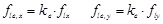 |
(6) |
where,
 |
(7) |
 |
(8) |
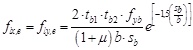
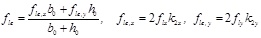
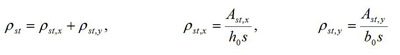
The volumetric steel reinforcement ratios ρst, x and ρst, y along x and y directions are defined considering the geometrical configuration of the internal and the external reinforcement, namely:
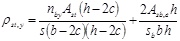 |
(9) |
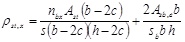 |
 |
(10) |
In Eq. (9) nbx and n by represent respectively the sum of the number of hoops arms and the number of additional ties in the direction parallel to b and h, Ast is the area of the internal hoops, c is the width of the concrete cover, s is the spacing of the internal hoops, Asb and sb are the area and the spacing of battens and Asb,e is the mechanical equivalent area of the battens.
After the determination of the effective lateral pressure it is possible to obtain the strength increment factor of concrete, in agreement to the abacus in Fig. (3), and to determine the column axial load capacity.
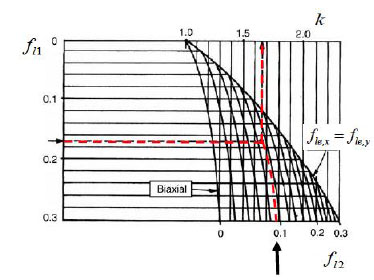
Abacus for the evaluation of the k strength increment factor of concrete for rectangular cross sections [9].
3.3. Model by Nagaprasad et al. (2009) [19]
Once again this model is an extension of the model proposed by Mander et al. [9] referred to rectangular cross-sections taking into account external steel angles and battens.
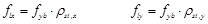
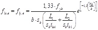
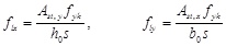
The authors propose a methodology for determine confinement pressure along the principal directions of inertia. If a uniform tensile stress fyb is assumed for the battens, the average confining pressure along both x and y direction exercised by the battens is expressed by:
 , , 
|
(11) |
The effective pressure is obtained considering the effectively confined area in plan and elevation, assuming an arching line of confining stresses between the steel angles. The arching line in question is assumed in the form of a second order degree parabola with an initial tangent slope equal to 45°. Therefore
 |
(12) |
 |
(13) |
| Se = S - (tb2 + 2C) | (14) |
Strain limits of the confinement model are defined by the model of Mander et al. [9] as a function of the above lateral confinement pressure.
3.4. Model by Badalamenti et al. (2010) [20]
For square columns reinforced with steel angles and battens, arranged in such a way that the angles are not directly loaded along their axes, an analytical model that considers action of confinement provided by the reinforcement as a function of the friction between angles and concrete members was formulated.
The confinement pressure in the plane of the strips, and in the volume of concrete between two consecutive strips due to steel angles and battens, are calculated following the concept that if a column is axially loaded it shortens and expands transversely proportionally to the Poisson ratio and to the transverse dimension of a member. Starting from a plane system it is possible to simplify the problem assuming a one-dimensional model and considering two elastic beams on a bed of springs placed in series (Winkler model) in order to determine the interaction between steel reinforcement and concrete.
The battens force F exercised to counteract the expansion of confined core is obtained with the following simplified expression:
 |
(15) |
The uniform confinement pressure assumes the maximum value when the battens are yielded (fyb) and the force F becomes tb1. tb2. fyb. In this case Eq. (15) can be simplified, assuming the equilibrium of cross-section considering the concrete as infinitely rigid body (Ec). Hence the maximum effective confinement pressure due to battens assumes the form:
 |
(16) |
In Eq. (15) tb2 is the thickness of the angles and tb1 the thickness of the battens, tb2 is the width of the battens, L1 is the width of the angles, L2 the length of battensin contact with column and sb the spacing of battens.
Assuming in Eq. (16) one obtains a simplified relation to derive the maximum confinement pressure:
 |
(17) |
The above confinement pressure is then used for the estimation of the strength of the confined concrete by a formula provided by EC2 that is reported in the section 5.
3.5. Capacity Model in Agreement to Italian Code NTC 2008 [15]
NTC 2008 does not define a methodology for the determination of the lateral pressure provided by steel jacketing, but it provides an analytical relation to obtain the strength of the confined concrete.
Steel jackets in agreement to the Italian Code can be applied to strength beam and columns through the confinement effect.
The effect of the confinement of a steel jacket is evaluated, as for the transverse steel rebars, with reference to the geometric percentage of the reinforcement along each of the transverse directions.
For the properties of the reinforced concrete, expressions of proven validity can be used, such as the following:
For the strength of the confined concrete:
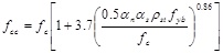 |
(18) |
For the ultimate strain of the confined concrete:
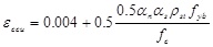 |
(19) |
where,
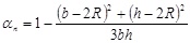 |
(20) |
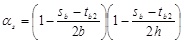 |
(21) |
 |
(22) |
ρst is the geometric ratio of transverse reinforcement, Asb the transverse area of the battens, sb the spacing of battens, αs and αn are the confinement efficiency factors depending respectively in the plane of the cross section and along the height. R is the curvature radius of the corners. It is fixed equal to 0 when the corners are not rounded.
3.6. Comparison Between Models for the Confining Pressure
Referring to the strengthened cross-section in Fig. (4) (geometrical and mechanical characteristics are inserted in Table 2) the confining pressure caused by the external reinforcement was evaluated by means of the models before discussed.
Main characteristics of the strengthened cross-section.
| (b) (mm) |
(sb) (mm) |
tbA (mm) |
tb1 (mm) |
tb2 (mm) |
L1 (mm) |
L2 (mm) | Fy/b (MPa) |
|---|---|---|---|---|---|---|---|
| 300 | 120 | 5 | 4 | 40 | 50 | 200 | 275 |
The goal was to give evidence of the strong differences between the models available in the literature. The comparison was performed varying the ratio sb/b between the dimension of the side of the square cross-section and the spacing of the battens. The comparison in question is shown in Fig. (5) where one can verify that it is common to the models analized the reduction of the confinement pressure increasing the ratio sb/b. Nevertheless strong differences can be found in the confining pressure for a fixed value of sb/b. In details the model by Nagaprasad et al. [19] reveals the highest values while the model by Braga et al. [16] reveals the lowest.
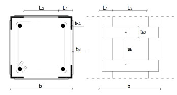
Geometrical scheme of a reinforced concrete cross-section.
The model by Montuori and Piluso [17] is very close to that by Nagaprasad et al. [19] while the model by Badalamenti et al. [20] shows a behavior intermediate between that of Nagapasad et al. [19] and Braga et al. [16] All the models shows similar values of the confinement pressure for values of the ratio sb/b greater than 0.8.
4. EXPERIMENTAL PROGRAM
Compression tests were carried out on columns in order to observe the behavior of concrete depending on geometrical arrangement of longitudinal and transverse reinforcement, on unconfined concrete strength and geometry of the columns. Columns reinforced with steel jacketing were also tested. The tests were carried out in displacement control to determine the load-strain response. An increasing monotonic displacement history was applied to the columns by a compression machine Zwick/Roell & Toni Technik having a capacity of 4000 kN, with a servo-hydraulic management system controlled by an electronic unit interfaced with the user by a PC.
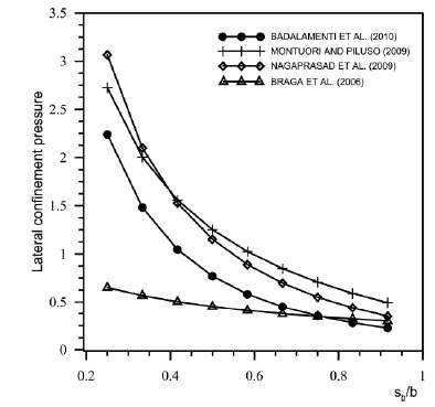
Comparison between the lateral confining pressure produced by cross-section external reinforcement evaluated by different models.
The displacements were evaluated with transducers having different gauge length. Specifically four of them had a gauge length equal to 25 cm, located in correspondence of the central part of the column, and the remaining four had a gauge length equal to the total height of the columns placed at the four corners (Fig. 6).
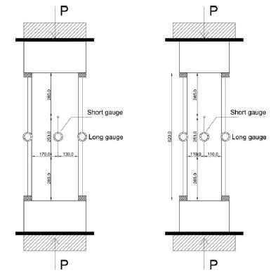
Geometric disposition of the transducers.
Concrete with medium strength (24.0 MPa - first series) and low strength (12.65 MPa - second series) was used combined with two different distributions of internal reinforcement, named A and B (Figs. 7, 8).
Regarding the first series the columns CCI1 and CCI2 had high percentage of steel reinforcement (type A distribution) and the columns CCI3 and CCI4 had low percentage of steel reinforcement (type B distribution). Moreover column CCIR1 (having internal reinforcement type B) was externally reinforced with steel jacketing system. Regarding the second series, columns CCII1 and CCII2 had low percentage of steel reinforcement and columns CCIIR1, CCIIR2 and CCIIR3 were also reinforced with steel jacketing. The experimental results were compared with the models above discussed.
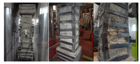
Steel jacketing was characterized by angles on column corners and battens welded with a spacing of 100 mm (Fig. 9). Angles were not directly loaded in the vertical direction. With this assumption the increase of strength was due to friction between angles and concrete cover. Moreover battens were welded without preheating, providing on columns a passive confinement.
5. TEST RESULTS AND COMPARISONS WITH THE AVAILABLE MODELS
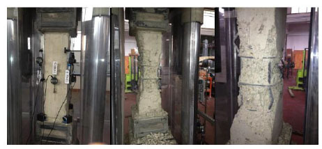
The geometrical characteristics of the specimens and a synthesis of the results in terms of peak strength, residual strength and corresponding strains are inserted in Table 3 evidencing the positive contribute of steel jacketing both in the cases of low strength concrete and medium strength concrete (see Figs. 10-12 for the state of the specimens at the end of the tests).
In Fig. (13) the load-strain curves obtained from compression tests on columns (with and without external reinforcement) are inserted.
Columns of the first series (concrete strength 24 MPa) exhibited, as expected, a bearing capacity greater than columns of the second series (concrete strength 12.65 MPa). Columns CCI1 and CCI2 (steel reinforcement type A) presented an ascending branch with higher stiffness than columns CCI3 and CCI4 (steel reinforcement type B). They also presented a strength greater than that exhibited by the columns belonging to the second series. Regarding the descending branch steel reinforcement of type B provided a high strain capacity and a greater ductility.
Externally strengthened columns of second series exhibited initially a load-strain curve similar to that one of the unstrengthened columns. The stress overcame the mean strength of the unreinforced columns, further a minor slope of the load-strain curve was exhibited up to the new strength peak. In this case the confinement of the steel jacketing triggered after the load arrived to a sufficient level. However a more than satisfactory increasing of load and deformation capacity was observed. The external strengthened column of the first series showed an ascending branch with higher stiffness. The greater stiffness and strength of the concrete delayed the activation of the external reinforcement and reduced its positive influence.
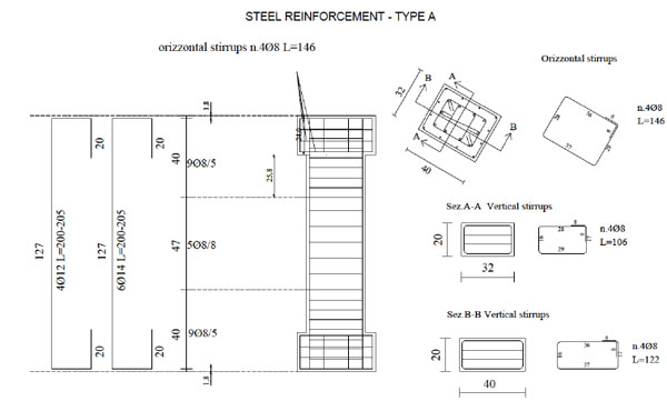
Details of test specimens: Steel reinforcement - Type A.
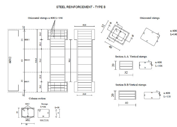
Details of test specimens: Steel reinforcement - Type B.
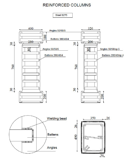
External reinforcement.
Specimen characteristics and test results.
| Specimens | Test Results | |||||||||
|---|---|---|---|---|---|---|---|---|---|---|
| Dimensions (cm) (b x h x l) |
fc (MPa) |
Steel reinforcement | Stirrups spacing (mm) |
plong (%) |
Steel Jacketing | Fmax (kN) |
Fu (kN) |
εcc | εccu | |
| CCI1 | 22x30x130 | 24.00 | Type A | 80 | 0.02083 | NO | 2476 | 2104 | 0.0036 | 0.0146 |
| CCI2 | 22x30x130 | 24.00 | Type A | 80 | 0.02083 | NO | 2285 | 1942 | 0.0051 | 0.0252 |
| CCI3 | 22x30x130 | 24.00 | Type B | 150 | 0.02083 | NO | 2055 | 1746 | 0.0028 | 0.0095 |
| CCI4 | 22x30x130 | 24.00 | Type B | 150 | 0.02083 | NO | 1845 | 1568 | 0.0029 | 0.0072 |
| CCIR1 | 22x30x130 | 24.00 | Type B | 150 | 0.02542 | YES | 2240 | 2074 | 0.0102 | 0.0202 |
| CCII1 | 22x30x122 | 12.65 | Type B | 150 | 0.01027 | NO | 1142 | 971 | 0.0040 | 0.0076 |
| CCII2 | 22x30x122 | 12.65 | Type B | 150 | 0.01027 | NO | 1195 | 1015 | 0.0044 | 0.0077 |
| CCIIR1 | 22x30x122 | 12.65 | Type B | 150 | 0.02542 | YES | 1849 | 1572 | 0.0288 | 0.0331 |
| CCIIR2 | 22x30x122 | 12.65 | Type B | 150 | 0.02542 | YES | 1882 | 1600 | 0.0220 | 0.0287 |
| CCIIR3 | 22x30x122 | 12.65 | Type B | 150 | 0.02542 | YES | 1898 | 1613 | 0.0336 | 0.0438 |
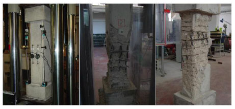
Columns of the first series: steel rebars type A.
Columns of the first series: steel rebars type B.
Strengthened columns: steel rebars type B.
For columns having type B steel reinforcement, post-yielding buckling of internal rebars happened and a consequent strength degradation was observed.
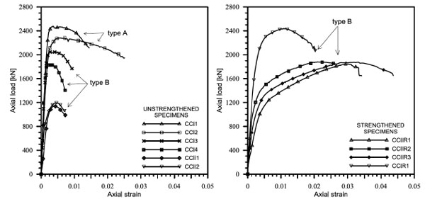
Axial force versus axial strain curves resulting from experimental tests.
5.1. Non External Strengthened Columns: Modelling of Experimental Results
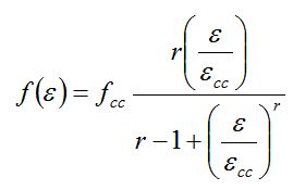
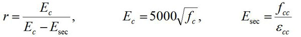
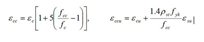
A comparison of the above experimental results with the models available in the literature highlights that the results in question can be reproduced if different stress-strain laws are associated to the different components of a cross-section, that are cover, rebars and core. After different attempts, the best results were obtained by using the Saatcioglu and Razvi’s model [9] for the concrete cover and for the concrete core (differentiated depending on the confinement pressure), and by using the law of Dhakal and Maekawa [21] for the longitudinal rebars.
The analytical model of Saatcioglu and Razvi [11] is characterized by the following relations:
Ascending branch : 0 ≤ ε ≤ εcc
 |
(23) |
Descending branch : ε > εcc
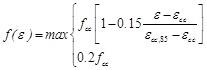 |
(24) |
where:
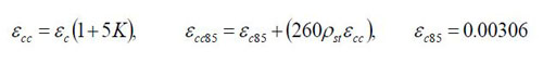 |
(25) |
In the first of Eq. (25) the parameter K assumes a form depending on the confinement pressure fle, that is
 |
(26) |
Further the confinement pressure is expressed as:
 |
(27) |
 |
(28) |
 |
(29) |
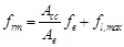
The geometrical parameters b0, h0, bi, hi and s are shown in Fig. (1). Finally the peak strength fcc appearing in Eqs. (23) and (24) has the form
 |
(30) |
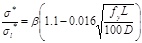
In the prediction of the response it was taken into account the cover spalling and the progressive transfer of the load to the core. Also the lost of bearing capacity of the longitudinal reinforcement, σ1 not adequately confined by stirrups, because of buckling was considered in agreement to the diagram in Fig. (14). In detail the constitutive law of steel in compression considered in this study is:
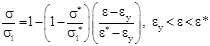 |
(31) |
 |
(32) |
 for for 
|
(33) |
 for for 
|
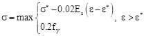
(34) |
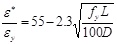
In the above equations, L and D are respectively the length between two consecutive stirrups and the diameter of the longitudinal reinforcement, σ1 is the stress corresponding to ε (current strain) and σ1* is the stress corresponding to ε* (strain at intermediate point). Similary, εy and Es are the yielding strain and the Young’s modulus of the reinforcing bars. The value β found to be 1.0 for linear hardening bars, and 0.75 for perfectly elastoplastic bars. For bars with limited hardening range, which are the most diffused, it should be chosen between 0.75 and 1.
Model for the longitudinal rebars.
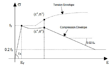
In Fig. (15) a comparison between the experimental results and the ones obtained by using the before mentioned models are shown. The comparisons in terms of load-strain curves are represented, also the rates of load absorbed by cover, core and rebars in agreement to the models used for them are included. The cover spalling and the buckling of the longitudinal rebars visible in the figure in question are consistent with what observed during each test. The comparison proves the good agreement obtainable between experimental and theoretical results, in terms of stiffness, peak of strength and strains in the post peak branch. At the same time it excludes, at least for the cases here examined, the possibility to use most of the models for the confined concrete before discussed because of the high difference from the model by Saatcioglu and Razvi [11]
Comparison between experimental and theoretical response for the non external reinforced specimens: a) longitudinal rebar distribution of type A, concrete strength 24 MPa; b) longitudinal rebar distribution of type B, concrete strength 24 MPa; c) longitudinal rebar distribution of type B, concrete strength 12.65 MPa.
5.2. External Strengthened Columns: Modelling of Experimental Results
In order to model the experimental results the confinement action of angles and battens was considered. In this way a proper stress-strain law for the concrete of the core and for the concrete of the cover was obtained. The volume of effectively confined concrete was evaluated depending on the arrangement of the external reinforcement. It was found that the model of confined concrete by Saatcioglu and Razvi [11] differently from the case of columns non externally reinforced did not ensure a good agreement with the experimental response. Therefore the law proposed by Mander et al. [9] was used, modified in the part that regards the evaluation of the lateral confinement pressure. For the evaluation of this pressure the model by Badalamenti et al. [20] was used. On the other hand, for steel rebars a hardening elastoplastic model was used considering that the external battens prevent post-yielding buckling of them.
The model by Badalamenti et al. [20] does not consider the contribute of the internal stirrups to the confinement. As a result the entire cross-section is interested by an unique stress strain law for the concrete.
The expressions to take into account for the modelling of strengthened sections are reported below:
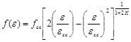
The stress-strain relationship for the confined concrete is a single law defined in the complete range for 0 < ε < εccu :
 |
(35) |
 |
(36) |
The following strain limits are fixed:
 |
(37) |
 |
(38) |
Also the ultimate strain of unconfined concrete εcu is fixed equal to 0.004 and the ultimate strain of steel reinforcement εsu is fixed equal to 0.075.
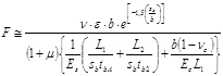
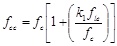
The effective confinement pressure was obtained by equation (17) inserting the greatest of the two dimensions of the rectangular cross-section of the specimens studied. The strength of the confined concrete was estimated by an analytical relation provided by Eurocode 8 [19]. That is:
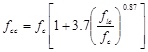 |
(39) |
Considering that angles were not directly loaded but axial load applied on columns was transferred by friction through the angles-column contact surface, the maximum load carried by angles (Na,max) was evaluated starting by the confinement pressure fle exerted by the angles. Taking the friction transferred from the concrete to the angles themselves into account and considering that the effective angle-column contact surface was limited to the part of the angles intersected by battens, the following expression was obtained for Na, max:
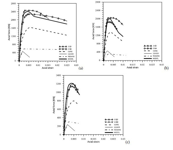
Comparison between experimental and theoretical model: strengthened specimens.
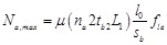 |
(40) |
where na is the number of angles (equal to 4 for rectangular cross-sections), µ is the friction coefficient, tb2 is the width of the battens, L1 is the width of each side of the angles, l 0 is the length of the angles while sb is the spacing of the battens.
The behavior of the angles was assumed elastoplastic depending on the strain in the concrete, that is:
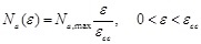 |
(41) |
 |
(42) |
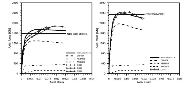
Under these hypotheses the comparison between experimental and analytical results gave the curves plotted in Fig. (16). In the same figure the contribute of the concrete, the rebars and angles are inserted showing that this external reinforcement is more effective for the strength increment of the concrete rather than the bearing capacity provided by the angles.
A comparison between experimental data and analytical model by Badalamenti et al. is shown in Fig. (16). Also the strength prediction by NTC 2008 is inserted. It can be noted that the load capacity suggested by NTC 2008 is slightly understimated than the analytical model by Badalamenti et al. [20] For the first series the difference in term of load is about 3%, while for the second series the difference is about 9%. The comparison between the NTC 2008 model and the experimental data show that the difference for the first series is more or less 4% and for the second series about 15 %.
A good agreement can be observed in the ascending and in the post peak branches.
CONCLUSION
The confined concrete models described in this paper give a clear idea of their differences and makes one aware of their characteristics. This should allows one to select the more proper according to the design objectives in the practical applications, even, if clear indications on the a priori reliability of one rather than another are not provided.
Regarding this aspect, a comparison between the results obtainable by using the models described and the results of an experimental campaign on ordinary columns under centered compression revealed that model by Saatcioglu and Razvi [11] combined with the model by Dhakal and Maekawa [21] for the rebars, allows to obtain a satisfactory matching in the ascending branch and in the post peak branch of the response, well predicting the observed strain and the corresponding load better than each other model.
The good results obtained by the combination of the above models were not affected by the strength of the unconfined concrete. Indeed, both in the cases of column made of concrete having low strength (12.65 MPa) and of columns made of concrete having a medium strength (24 MPa), an optimal agreement with the experimental results was observed.
Experimental results on the compressive behavior of R.C. columns externally strengthened with steel angles and battens are presented and discussed. Results obtained highlighted the advantages both in terms of strength and ductility due to the presence of external caging.
However, the above modeling strategy did not give the same satisfaction in the case of columns externally strengthened by angles and battens: in this case the confined concrete model by Mander et al. [9] was combined with the model by Badalamenti et al. [20] for the prediction of the lateral confinement pressure in order to obtain the better matching (in the case of columns characterized by low strength concrete a slight underestimation was observed, while for columns characterized by concrete having medium strength the results matched better).
The study in this paper highlights once again the complexity of the phenomenon of the concrete confinement and the numerous physical parameters that affects it. Furthermore the comparison between experimental and numerical results makes a belief arise: the available models need a classification in such a way to recognize in which cases each of them can be used. This is in opposition to the actual tendency to consider the models in questions exchangeable.
Finally is useful to observe that Italian Codel provides a good results in term of load capacity for concrete having medium strength (as the concrete used for the first series) while for concrete having low strength the load capacity is understimated.
This underestimation allows to design with a high margin of safety, but is likely to obtain a oversizing of the strengthening system.
Abbreviations
CONFLICT OF INTEREST
The authors confirm that this article content has no conflict of interest.
ACKNOWLEDGEMENT
Declared none.

