All published articles of this journal are available on ScienceDirect.

Seepage Control in a High Concrete Face-Rock Fill Dam Based on the Node Virtual Flow Method
Abstract
The seepage control system of a high Concrete Face Rock-Fill Dam (CFRD) may have anti-seepage deficiencies during both construction and operation. In order to solve these, the three-dimensional Finite Element Method (FEM) model was built based on dam body filling, anti-seepage system, defect location and bedrock distribution. The seepage field simulation and computation were carried out using an improved node virtual flux method and the zero-thickness crack model theory. The water head distribution, seepage lines and dam leakage field were obtained by simulation under different conditions, and the seepage characteristics during construction and operation were analyzed systematically. Taking a high CFRD as an example, the results showed that during the flood-control construction period, the incomplete nature of the dam face slab can lead to seepage damage near the second seepage control line. Moreover, during operation period; the seepage control system was still effective when the dam face slab was incomplete.
INTRODUCTION
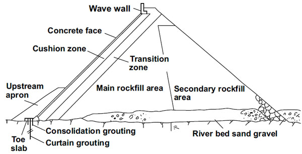
Reinforced CFRD is widely used nowadays. Its anti-seepage system comprises mainly body and foundation anti-seepage measures. The anti-seepage body includes wave wall, a concrete face, and a toe slab and joint water stop for water retention. A cut-off wall and grout curtain are usually adopted as the foundation anti-seepage measures [1].The anti-seepage components of a CFRD are shown in Fig. (1). The anti-seepage system, usually called the first seepage control line, has been successfully applied to Shuibuya hydropower station in China. In this project, CFRD has a maximum height of 223 m [2]. Engineering practice shows that, when the CFRD exceeds 150 m in height, seepage control is the key technical issue. The integrity of the anti-seepage reinforced concrete face is vital, and it will affect the operation and safety of the dam directly. For example, due to the failure of anti-seepage concrete face, the Gouhou concrete-faced sand gravel dam in Qinghai, China, suffered dam slope instability and final dam-break [3]. Similar events occurred at Zhu Shuqiao CFRD, Hunan, China [4] and Campos Novos CFRD in Brazil [5], and both were caused by broken face joints and increased seepage rates resulting in dam malfunction.
Seepage analysis of the finite element method (FEM) can be divided into variable grid and fixed grid method. Fixed grid method has been widely applied at present. Such as Mohammad and Farhang [6] put forward a smoothed fixed grid finite element method (SFGFEM), which was used to simplify the solution of variable domain problem of unconfined seepage. And based on the fixed grid method, Zhang and Wu [7], Shu et al. [8], and Cui and Zhu [9], established an improved cut-off negative pressure method, element conduct matrix regulative method, and improved nodal virtual flux method, respectively. The methods were successfully applied to seepage with free surface.
Some reported studies were focusing on the reservoir dam seepage using FEM. Asteris and Tzamtzis [10] have presented a methodology for the earthquake response analysis of concrete gravity dam-reservoir systems. The earthquake response of the system may increase the amount of seepage in reservoir. Chen et al. [11] Establishing a numerical model which can describe the whole process from the enlargement of the seepage passage. Chen et al. [12] used the improved node virtual flow method and zero thickness crack model to solve the crack seepage problem in a CFRD. Chen et al. [13] established a coupled non-linear elastic deformation and non-steady seepage flow model for performance assessment of the CFRD, which model was applied to capture the seepage flow and deformation behaviors of the SHUIBUYA CFR dam in China. Chen et al. [14] solved the problem of seepage safety of middle-small earth-rock dam after using the Fortran program with improved nodal virtual flux method. Pan et al. [15] established a soil geology model of the reservoir slope to analyze the slope stress analysis of seepage-stress field under the condition of water lifting of reservoir slope. GUO et al. [16] quoting a case study of XIQUANYAN dam in China, and then analyzed and determined the seepage coefficient. At the same time, the seepage field, as well as the seepage stability is numerically analyzed using the FEM-based SEEP/W program.
Incomplete seepage control can occur at two stages. The first stage is in construction, when the concrete face is not complete. The second stage is during operation, when concentrated seepage is induced by the defects in the concrete face and/or the joint water stop. While the seepage control system is incomplete, the anti-seepage capacity of the second seepage control line, the cushion and transition layer, and the seepage stability of the dam will be extremely important. In this study, based on the improved node virtual flux method and zero-thickness crack model, a high face rock-fill dam is studied as an example. The dam with defects in concrete fale, the seepage fields of the dam during construction and operation were simulated using the 3D numerical method. By analyzing the water head distribution, and seepage lines and rates in the dam, the seepage ability of the second seepage control line and the overall seepage stability of the dam can be obtained. The results yield theoretical guidance and technical support for similar engineering.
2. CALCULATION METHODS
2.1. Node Virtual Flow Method
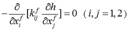
According to the continuity equation of water flow and Darcy’s law, the three dimensional, stable saturated seepage control equation for heterogeneous anisotropic porous media can be written as:
 |
(1) |
Where, xi is the space coordinate, i =1,2,3; kij is the tensor of the saturated permeability h coefficient, is the total head, which includes the position and pressure heads; and Q̅ is the source term in the seepage analysis area.
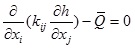
The boundary conditions are shown in Fig. (2). The node virtual flux method is presented by Su and Zhu [17] (1991), for solving this problem. The basic finite element iterative format is:
 |
(2) |
Where, [K] and [K2] are total seepage matrices determined by global and virtual fields using boundary conditions, respectively; {h} is the head array of the unknown node; {Q} and {Q2} are flow arrays contributed by the known head node, inner source term and flow boundaries of the global and virtual fields, respectively.
2.2. Improvement of Node Virtual Flow Method
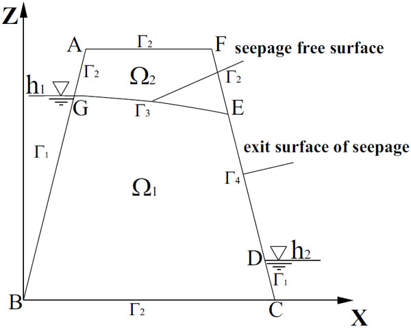
As the node virtual flux method is inadequate, an improved method is needed for simulating the total dam area under various conditions for a high CFRD. The success of the node virtual flux method lies in finding a solution for the virtual area of the transition element in [K2]. Precise grid encryption depends on experience and judgment, however, which is obviously unsatisfactory. Hence, when the program is used to solve the conductance matrix [k]z contributed by the virtual area of transition element, encrypted Gaussian point technology is introduced [18], and converted to an isoparametric element as [9, 13]:
 |
(3) |
Where ng is the number of encrypted Gaussian points in each coordinate direction, which can be increased to 7, and substantially refines the grid cell around the free surface to improve precision; Wi, Wj, Wm are the weighted values of each coordinate direction; F(ξi, ζj, ηm) is the integrand with (ξi, ζj, ηm), the coordinates of the Gaussian point; Hε(p) is the continuous penalty function used to solve the problem that the contribution of the transition elements cannot be considered sufficiently while solving [k]2 by the encrypted Gaussian method.
The improvement to the method is that the Gaussian points are encrypted while solving the key matrix [k2] in equation (2), so that the precision of the calculations for large elements is ensured.
Zero-Thickness Crack Element Model
When face deficiency occurs at a joint, the water flow can be considered as relatively smooth, with approximately unchanging width [19] and the cubic law describing it properly [20].
In order to reduce grid quantity and improve calculation efficiency, as concrete face and joint water stop crack defects are always small, and the normal permeability of a crack is much higher than that of concrete, the loss of normal water head at the joint can be ignored. Thus the seepage can be treated as being quasi two-dimensional and non-thickness surface crack elements can be used in the simulation. Crack seepage can be obtained by:
 |
(4) |
Where, xif is crack-related local coordinate; and xijf is the two-dimensional permeability tensor of the crack surface element, which can be used to reflect the permeability anisotropy of the crack.
The equation for the conductance matrix of crack surface elements [21], kijfe is:
 |
(5) |
Where, sf is the crack element domain; Ni and Nj are the interpolation functions of the surface crack element of a joint and m is the node number of the joint surface element.
When the conductance matrix of each crack element is obtained, like other elements of CFRD, the matrix in equation (2) is used.
3. CASE STUDY
3.1. Project Profile
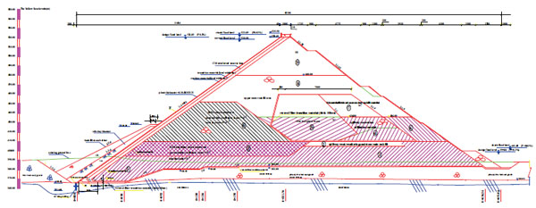
The hydropower project chosen for the study is large (2) type, with a first-grade dam structure. The maximum height of the CFRD is 154 m. Sections of the dam and fill materials are shown in Fig. (2). The dam is in the middle of a U-shaped bend on the river and a small overbank is developed on the right side by the dam. The left bank is relatively weathered, and the dam is backfilled in nine partitions, including limestone, sandstone, shale and gravelly sand, etc.
Due to the differences between in performance of the various fill materials and the issue of flood retention during construction, and in order to obtain the right analysis to evaluate the seepage safety of the dam, the study related to seepage problems occurring in floods during construction and to local defects in the concrete face during operation, using three-dimensional simulation.
3.2. Calculation Conditions
Because of its structural features and filling requirements, this CFRD study needs meshing generation during meshing encryption around the seepage control measures, with larger variation of seepage factors, then carrying out simple generation in rock-filling body of the dam which is always waterless or with limited variation of seepage factors. This enables development of a three-dimensional, finite element computational grid of the seepage field with proper density and high quality as shown in Fig. (3). The model consists mainly of isoparametric elements with eight hexahedron nodes, comprising 100,192 elements and 106,847 nodes in all as shown in Fig. (4).
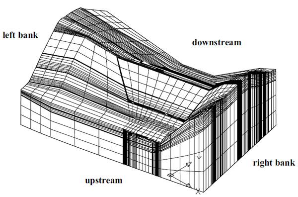
Because of its characteristics, the basic rock mass is also well simulated in the mesh. The rock mass is discriminated as: below 1 lu line, 1 lu ~ 3 lu line, 3 lu ~ 10 lu line and over 10 lu line.
Taking native groundwater into account, the model’s scope for the right bank is restricted to the watershed. Its scope for the left bank is wider, because the dam abutment has a weaker ridge, and is the watershed between the reservoir and the downstream river, which causes bypass and downriver seepage problems. In this project, the model’s left bank boundary is 590 m from left side of the maximum profile, and that of the right bank is 340 m from right side. The model’s foundation boundary is 260.0 m for scale height, and its crest elevation is the dam body elevation with natural terrain. To improve the seepage calculations precision, the grid density of the three-dimensional model is greater at the river bed.
| S.No | Name of the Material | Permeability Coefficient cm/s | Allowable Water Surface Slope (Dimensionless) |
|---|---|---|---|
| 1 | Concrete face, toe slab and downstream anti-seepage board | 1.0×10⁻⁷ | 200 |
| 2 | Material for cushioning layer and material for inverted filter layer | 1.0×10⁻⁴ | 1.2 |
| 3 | Material for transition layer | 2.0×10⁻² | 1.2 |
| 4 | Zones 1 and 2 of main rock fill | 1×10⁻¹ | 10 |
| 5 | Zone 3, 6, 8 and 9 of main rock fill | 1×10⁻² | 10 |
| 6 | Zone 4, 5 and 7 of main rock fill | 1×10⁻³ | 10 |
| 7 | Main encroachment of weak-weathered sandstone in spillway | 1.0×10⁻² | |
| 8 | Gravelly sand material of river bed | 1.0×10⁻² | |
| 9 | Gravel of river bed | 1.0×10⁻² | |
| 10 | Oversized stone backfilling | 1 | |
| 11 | Silt applied to the bottom of the upstream dam slope | 1.0×10⁻⁵ | / |
| 12 | Ballasting upper part of the upstream dam slope | 1.0×10⁻² | / |
| 13 | Curtain grout | 1.0×10⁻⁵ | 18 |
| 14 | Material for digging spillway | 1.0×10⁻² | |
| 15 | Fresh bedrock (below 1 lu line) | 8.1×10⁻⁶ | / |
| 16 | Weak weathering (1 lu line to 3 lu line) | 3.9×10⁻⁵ | / |
| 17 | Strong bedrock weathering (3 lu line to 10 lu line) | 4.8×10⁻⁵ | / |
| 18 | Completely weathered layer of bedrock (above 10 lu line) | 2.6×10⁻⁴ | / |
The permeability coefficients of the materials listed in Table 1 refer to hydrogeological materials and reference values. The scheme design data are given in Table 2. It should be noted that the Defect impact analysis Y1 refers to the assumption that crushing failure occurs at an elevation of about 428 m to 430 m in the maximum profile in the middle of the dam,with a failure crack width and length of 0.5 and 2.0 m, and permeability coefficient 10-1 cm/s. Defect impact analysis Y2 refers to the assumption that crushing failure occurs at the joints of the bed slab and the left and right banks, with crack width 0.02 m and permeability coefficient 10-2 cm/s.
| Allowable Water Surface Slope | Upstream level/m | Downstream level/m | Seepage control condition | ||
|---|---|---|---|---|---|
| Flood retaining state in construction period | S1 | Flood stage reached in 2013 (200-year return period) | 459.64 | 381.00 | No concrete face |
| S2 | Flood stage occurs in 2014 (200-year return period) | 516.43 | 399.56 | The first and second phases of faces are available. The third phase of face is unavailable | |
| Normal operation | Normal pool level | 521.85 | 399.56 | Complete | |
| Defect impact analysis | Y1 | Normal pool level | 521.85 | 399.56 | Crushing failure occurs to the joints of concrete faces in the middle river bed |
| Y2 | Normal pool level | 521.85 | 399.56 | The joint between the toe slabs of both bands is ripped and broken. | |
3.3. Analysis and Evaluation of Results
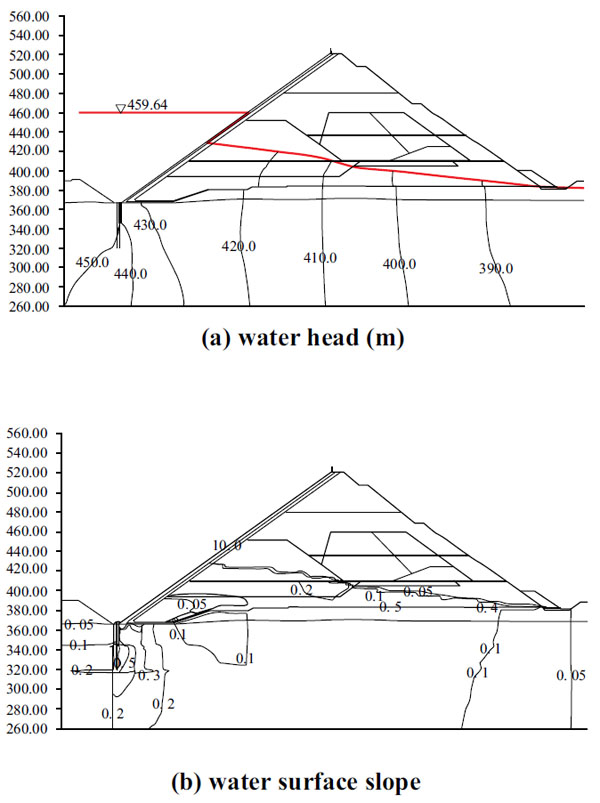
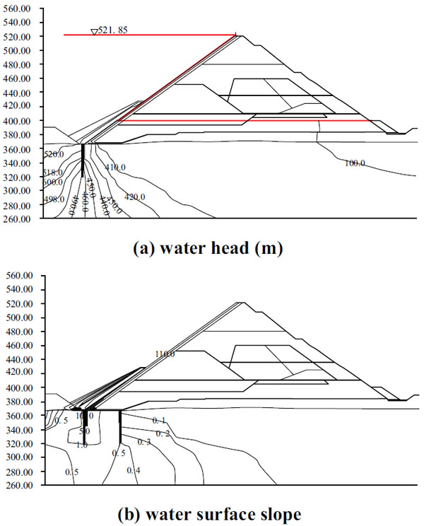
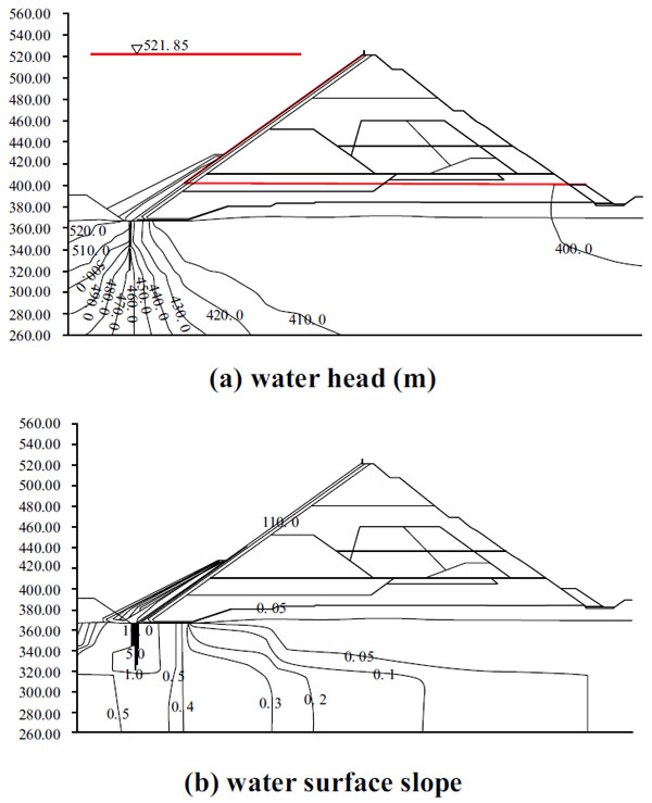
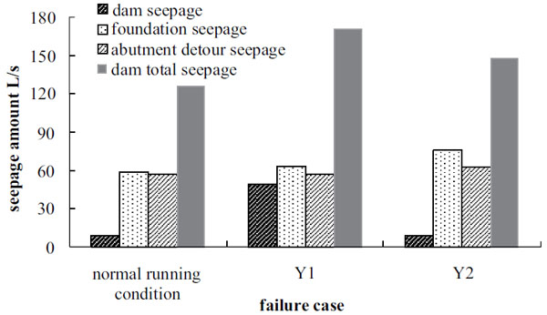
Figs. (5 and 6) are contour maps of the water head and surface slope under two construction conditions during the flood season. Figs. (7 to 9) are contour maps of water head and surface slope arising from facial defects during normal operation. Fig. (10) is a seepage comparison for facial defects in normal operation.
3.4. Analysis of Flood Retaining During Construction Period
The results show that, during flood retention in construction, without face S1, the water head distribution, cut-off wall and toe slab fail to form a complete anti-seepage system in the headwaters of the dam due to the absence of a setting face and connecting board. Groundwater bypasses the diaphragm wall and impervious curtain to flow into the dam tail water, so lowering of the phreatic line in the dam relies mainly on the relative impermeability of the cushioning layer and rock-fill. For the percolation gradient, the cushioning layer material in the dam’s upstream face can only be used as the main anti-seepage body for temporary water retention, because its osmotic gradient is relatively large with a maximum value of 13.79, far exceeding the 1.2 permissible.
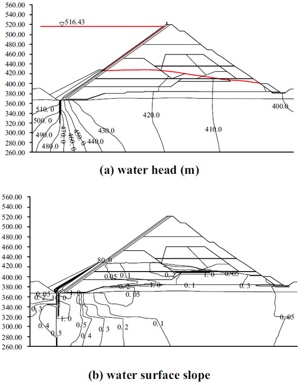
During construction in the flood season, S2 is based on the assumption that construction of the first and second phase faces is complete, but the third phase is not, when the flood stage upstream of the dam is 516.43 m. The results calculated show that the first and second phase faces play a partial anti-seepage role. The maximum slope of the concrete face is 85.71 and it provides some protection to the cushioning and transition layers (the second seepage control line). The osmotic gradient of the cushioning layer is 5.30, which exceeds the 1.2 permissible. This is a significant reduction compared to that under S1, even allowing for the increased difference of in head upstream and downstream of the dam.
During flooding in the construction period, the rock-fill inhibits seepage from upstream, but water retention relies mainly on the second seepage control line, i.e. the anti-seepage effects of the cushioning and transition layers. While the percolation gradient exceeds the permissible value, a long period of retention of high water head in the flood season usually leads to seepage failure. In other words, it should not be treated as a long-term water retaining measure. The necessary protection should be provided to the upstream face of the cushioning layer before the flood season. After flood season, the cushioning layer’s quality should be checked to ensure that it has not deteriorated.
3.5. Analysis of Local Anti-Seepage Defects
The basic isoline distribution law of water head in normal operation is that the head distribution law is reasonable across the whole seepage field, starting from normal water stage upstream against the concrete face, whose free surface sharply decreases and becomes horizontal in the rock-filling zone, and this seepage control system plays an effective part in anti-seepage.
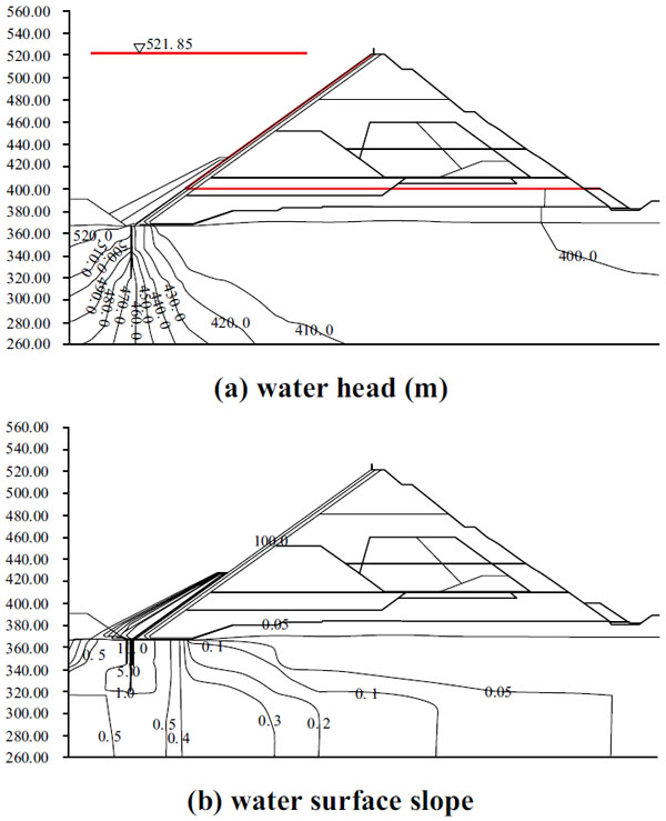
The water head in the cushioning layer behind the face increases when crushing failure occurs in the vertical joint in the middle face of the river bed (Y1). The maximum height of the free surface in the cushioning layer increases by 0.43 m and in the rock-fill by 0.5 m. When the joint between the toe slabs on both banks and face is ripped (Y2), the free surface of the back-slope of the cushioning layer rises. The maximum rise of the free surface in the rock-fill is 0.32 m. The calculations show that local damage to the anti-seepage system will affect water head distribution to some extent, but the change is not obvious and the anti-seepage system is still effective.
During normal operation, water surface slope is confined mainly to major anti-seepage components like the face, cushioning layer, toe slab, impervious curtain, etc. The maximum water surface slope occurs in the concrete face with a value of 112.72. The seepage slope in the cushioning and transition layers falls to less than one. The percolation gradient in all parts of the dam and its foundation is within the permissible range, so no seepage is shown. When the local vertical joint in middle face of the river bed (Y1) fails by crushing, its percolation gradient increases to 122.31, and those of both the transition and cushioning layers increase, e.g. the cushioning layer gradient around the damaged area rises to 1.26, which exceeds the permissible water surface slope. When tearing damage occurs at the joint between the toe slabs of both banks and face (Y2), the cushioning layer percolation gradient within the damaged area increases to 1.38 i.e., above the permissible water surface slope. Again, the calculated results show that, in the case of defects caused by local damage to the anti-seepage system, the water surface slope of the second seepage control system e.g., the cushioning and transition layers of the damaged area increases and exceeds the permissible value, but the combined supporting anti-seepage effects of the cushioning and transition layers, and the rock-fill, can still keep seepage within safe limits.
As can be seen in Fig. (10), when local face damage occurs during normal operation, the seepage rate changes everywhere. Seepage occurs mainly in the dam foundation at 59.2 L/s. The seepage rate is 9.44 L/s in the dam body, and total seepage is 125.98 L/s. If there is crushing failure of a local vertical joint in the middle face of river bed (Y1), the seepage from dam foundation and abutment by-pass and of both banks remains unchanged. Seepage from the dam increases greatly, however, to 49.83 L/s. Tearing damage to the joint between the toe slabs of both banks and face (Y2), cause no seepage from the dam, but that from both the dam foundation and abutments increases. Dam foundation seepage increases to 76.64 L/s.
Crushing failure on a local vertical joint in the middle face of the river bed (Y1), causes total seepage from the dam area to increase significantly to 170.59 L/s.
CONCLUSION
The seepage control system of a high Concrete Face Rock-Fill Dam (CFRD) may have anti-seepage deficiencies during both construction and operation. In order to solve these, the three-dimensional Finite Element Method (FEM) model was built based on dam body filling, anti-seepage system, defect location and bedrock distribution. The seepage field simulation and computation were carried out using an improved node virtual flux method and the zero-thickness crack model theory. The results from the improved node virtual flux method when used to calculate the unconfined seepage field of a tall CFRD project conform to the basic law of three-dimensional seepage in the dam area. The zero-thickness crack model can effectively simulate the seepage caused by local defects in the dam’s anti-seepage system and help to avoid the adverse effects on solution accuracy caused by the greater difference between the traditional equivalent continuum crack and peripheral element size, which can be used for future seepage field analysis.
If an incomplete face is used for flood retention during construction, significant seepage will occur at the second seepage control line (cushioning and transition layers) of tall CFRDs. Long-term water retention tends to cause seepage failure and is bad for the seepage stability of a dam. Because of this, protection before the flood season and checking after it are advocated strongly.
In normal operation, local defects on the dam face will increase the seepage rate and slope of the second seepage control line, in defective parts. Due to the complementary anti-seepage effects of the cushioning and transition layers, and the rock-fill, however, the seepage control system is not usually affected and the dam can still retain water.
CONFLICT OF INTEREST
The authors confirm that this article content has no conflict of interest.
ACKNOWLEDGEMENTS
This work was supported by Zhejiang provincial natural science foundation (Grant No. LQ15E090003) and The National Natural Science Foundation of China (Grant No. 51309101). National Science and Technology Major project of China (Grant No.2014ZX03005001).

