All published articles of this journal are available on ScienceDirect.

Experimental and Theoretical Investigation of Bending in Concrete Beams Strengthened with External Prestressing CFRP Tendons
Abstract
The flexural properties of concrete beams strengthened by external prestressing carbon fibre-reinforced plastic (CFRP) tendons are studied through static loading tests. The loading processes, failure modes, right-sectional strain features, and ductility of the strengthened concrete beams are analysed, permitting comparisons of the influences of the bending angle of the external CFRP tendons, the strength grade of the concrete, the reinforcement ratio of the internal non-prestressing steel, and the loading strengthening level of the external prestressing CFRP tendons on the flexural properties of the beams. Test results show that the external prestressing CFRP tendons can improve the anti-cracking properties, stiffness, and flexural properties of concrete beams. The bending angle of the external CFRP tendons should not exceed 10°, while the reinforcement ratio and loading strength have obvious effects on the flexural properties of the beams they reinforce; conversely, the strength grade of the concrete has relatively little influence on the flexural properties. Based on the results, a bending bearing capacity formula for concrete beams strengthened with external prestressing CFRP tendons is determined according to the design theory of externally prestressed concrete structures; this formula provides the accuracy required for construction and therefore it can be used as a reference for practical engineering.
INTRODUCTION
With the gradual maturing of global highway networks, fewer new bridges are being built, allowing traffic departments to focus on the reinforcement and improvement of extant bridges. Among the existing bridge designs, a number of small- and mid-span reinforced concrete beam bridges with low-loading designs have become crucial to highway updating [1].
The technique of external prestressing, which originated in Europe, is an active, not passive, reinforcement method. With advantages including uninterrupted traffic flow, rapid construction, safety, and economy, external prestressing is being applied to many old bridges, with significant economic and social benefits [2]. Because steel, the traditional external prestressing material, is more likely to suffer from corrosion damage and thereby impair the bearing capacity of bridges over time, carbon fibre-reinforced plastic (CFRP) tendons have recently begun to replace steel strands in external prestressing structures [3]. Precedents include the Hisho Bridge in Japan (1993) [4], the Bridge Street in the USA (2002) [5], and the Heyu Bridge in China (2007) [3]. Because CFRP tendons are high-strength, lightweight, and resistant to corrosion and fatigue, they can be used to replace steel strands and solve the problems related to durability in external-prestressing-strengthened structures. However, there has been relatively little research is into the reinforcement mechanism [6, 7], construction technology [8], structure [9, 10], and influencing factors [11] of CFRP tendons. Therefore, further study is necessary to clarify these issues. External prestressing with CFRP tendons is different from stiffening with polymer-based mortar layers [12-15]. The latter is designed to reinforce the expansion sections of a concrete structure. In this way, internal prestressing CFRP tendons can be used to reinforce bending beams. One shortcoming is that the mortar layers will increase the weight of the beams.
We poured 13 reinforced concrete rectangular-section beams that were strengthened with external CFRP tendons. In static load tests of the simply supported beams, we studied the flexural properties of the strengthened concrete beams. Our studies included analyses of the influences of the arrangement of the CFRP tendons, concrete grade, reinforcement ratio of the internal non-prestressing steel, and the loading of the external prestressing CFRP tendons on the flexural properties of the beams. We discussed a formula for defining the bending bearing capacity of concrete beams strengthened by external prestressing CFRP tendons and developed a design theory for external CFRP tendons. These principles could be used as references for further research and applications of strengthening with external prestressing CFRP tendons.
1. EXPERIMENTAL STATE
1.1. Test Beam Design
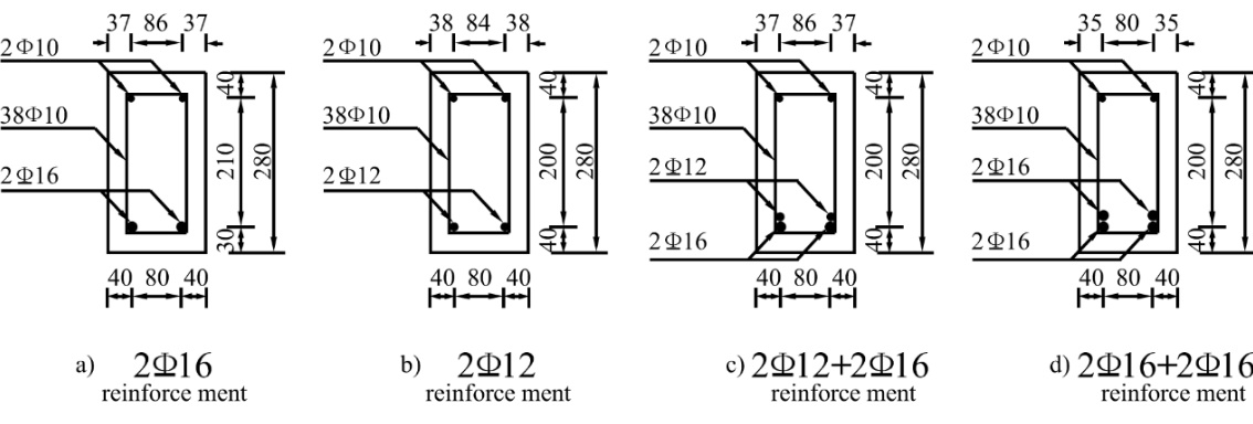
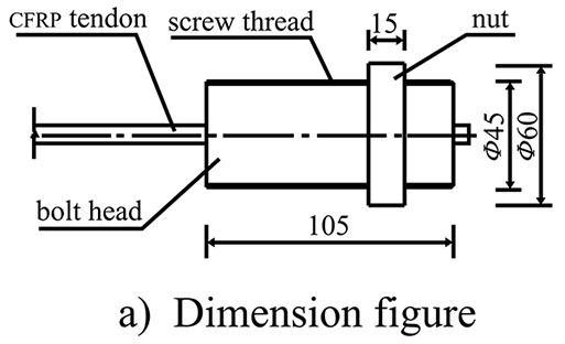
Thirteen test beams were designed based on the principle of ‘strong in shearing capacity, weak in bending bearing capacity’, with identifying numbers and main experimental parameters as shown in Table 1. The beams were 3.5 m in length, with calculated spans of 3.3 m. The length of each beam was 3.5 m, in order to guarantee the design and installation of the anchoring and turning devices. In this way, a beam can exhibit large-scale pure bending. A vertical HRB335 tensile steel bar was installed under the bottom of the beams. Four different reinforcement styles, namely, 2Φ12, 2Φ16, 2Φ12+2Φ16, and 2Φ16+2Φ16, were used to provide different reinforcement ratios. A vertical HPB235 bar was installed on top of the beams in the 2Φ10 reinforcement style. The stirrup was a Φ10 HPB235 bar. Within a range of 0.8 m near the middle of the span, the interval was 160 mm, while at the ends, the interval was 80 mm. The mechanical parameters of the steel bars are listed in Table 2, and the sectional size of the test beams and internal reinforcements are shown in Fig. (1). The CFRP tendons were CFM7-1 units (OVM Company, Liuzhou, China) were installed symmetrically at each side of the beam bottom. The distance between the beam bottom and the CFRP tendons was 60 mm. The mechanical parameters of the CFRP tendons are listed in Table 3. The CFRP tendons were installed externally in both straight-line and fold-line configurations. In the fold-line configuration, turning devices were installed at the fourth points of the beams with turning angles of 5°, 7°, and 12°. The CFRP tendon anchors consisted of bolt heads, nuts, and clamping pieces, as shown in Fig. (2). The concrete grades were C25, C30, and C40, cured for 28 days under standard conditions, with average measured compressive strengths of 26.8 MPa, 32.2 MPa, and 40.9 MPa, respectively.
| Number of test beams | Concrete grade | ps(%) | External CFRP tendon | Pre-splitting test load before reinforcement | Test consideration | |
|---|---|---|---|---|---|---|
| diameter (mm) |
σcon(MPa) | |||||
| B30-16 | C30 | 1.01 | 2Φ7 | 0.5fptk | —— | datum line beam |
| S30-16-0-80 | C30 | 1.01 | 2Φ7 | 0.5fptk | 80%Pu unloaded | turning angle |
| S30-16-5-80 | C30 | 1.01 | 2Φ7 | 0.5fptk | 80%Pu unloaded | |
| S30-16-7-80 | C30 | 1.01 | 2Φ7 | 0.5fptk | 80%Pu unloaded | |
| S30-16-12-80 | C30 | 1.01 | 2Φ7 | 0.5fptk | 80%Pu unloaded | |
| S25-16-5-80 | C25 | 1.01 | 2Φ7 | 0.5fptk | 80%Puunloaded | concrete grade |
| S40-16-5-80 | C40 | 1.01 | 2Φ7 | 0.5fptk | 80%Pu unloaded | |
| S30-12-5-80 | C30 | 0.57 | 2Φ7 | 0.5fptk | 80%Pu unloaded | reinforcement ratio ρs |
| S30-16(12)-5-80 | C30 | 1.90 | 2Φ7 | 0.5fptk | 80%Pu unloaded | |
| S30-16(16)-5-80 | C30 | 2.45 | 2Φ7 | 0.5fptk | 80%Pu unloaded | |
| D40-16-5-60 | C40 | 1.01 | 2Φ7 | 0.5fptk | 60%Pu loaded | different loading level |
| D40-16-5-70 | C40 | 1.01 | 2Φ7 | 0.5fptk | 70%Pu loaded | |
| D40-16-5-80 | C40 | 1.01 | 2Φ7 | 0.5fptk | 80%Pu loaded | |
| Strength grade | Steel diameter (mm) |
Measured diameter (mm) |
Elongation (%) |
Yield strength (MPa) |
Ultimate strength (MPa) |
|---|---|---|---|---|---|
| R235 | 10 | 10 | 24.40 | 280.07 | 410.62 |
| HRB335 | 12 | 11.5 | 22.32 | 301.36 | 464.00 |
| HRB335 | 16 | 15.6 | 20.60 | 406.55 | 539.16 |
| Nominal diameter (mm) |
Area(mm2) | fptk(MPa) | Ep(GPa) | µ |
|---|---|---|---|---|
| 7 | 38.485 | 1975 | 140~150 | 0.26 |
1.2. Anchoring and Turning Devices
For structures that are prestressed by CFRP tendons, the ultimate structural bearing capacity depends on the capacity of the tendon anchors. Three varieties of anchoring methods are currently in use, including beam-end anchorages, tooth-plate anchorages, and steel-plate anchorages. In this study, we conducted a comparative analysis of these methods and chose the steel plate anchorage as the design for the anchoring and turning devices for the CFRP tendons [16].
Fig. (3) shows the anchoring and turning devices used for the CFRP tendons. A steel plate next to the beam was welded to a U-anchor foundation to form each anchoring device. The turning device consisted of a steel plate next to the beams, inclined-strut steel plates, and a turning casting. Both the anchoring and turning devices were connected to the beams with M16 high-strength bolts. Using the design principles for suspension bridge saddles as guidelines [17], the bending radius of the turning casting was set to 1210 mm. Polyfluortetraethylene plates having a thickness of 2 mm were installed between the turning castings and external CFPR tendons in order to reduce the frictional losses of the tendons. During installation of the anchoring and turning devices, the contact surfaces between the steel plates and the concrete were treated with structural adhesive to ensure the safety of the structure.
1.3. Load Device and Measuring Details
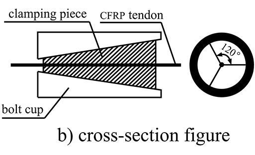
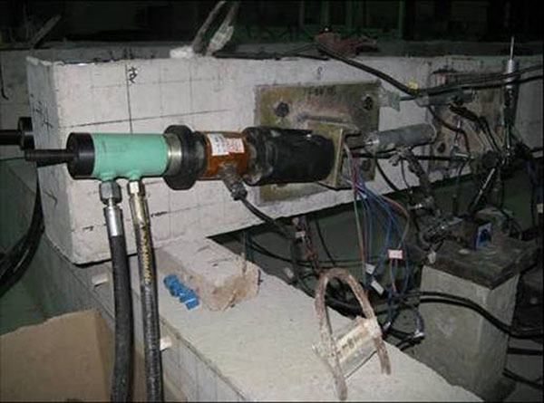
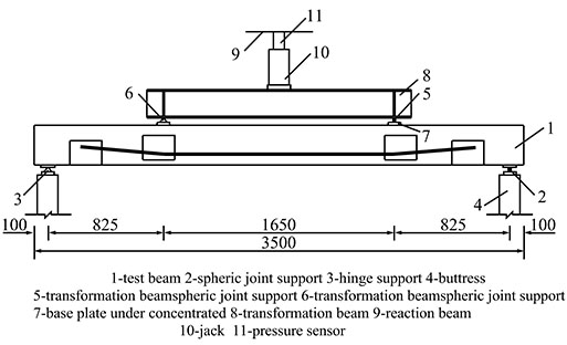
The CFRP tendons were tensioned by centre-hole jacks; the tension-controlled stress was measured by centre-hole sensors. As shown in Fig. (4), the two CFRP tendons located on the same side of the test beam were tensioned symmetrically and simultaneously in increments of degrees. The monotonic tension was increased by 3° to the chosen controlled stress; at each degree, the tension was maintained for 10 min. A mechanical jack was used to apply the monotonic loading of the test beams by degrees with a transformation beam. Measurements were taken at each degree of the displacement of the controlled section, the concrete strain on the section in the middle of the span, the strain in the internal non-prestressing steel, the strain in the CFRP tendons, and the development of cracks in the beam. A schematic representation of the test beam loading is shown in Fig. (5).
To simulate the actual loading properties of old bridges, different schemes were utilized for the non-loading and loading of the strengthened beams. For non-loading, pre-splits were introduced and cracks were repaired, strengthening was established by external prestressing, and then loading was performed by degrees until the beam exhibited damage. For loading, unloading and crack repair operations were not performed. Strengthening by external prestressing was conducted simultaneously with pre-splitting. Loading continued from the beginning of strengthening until damage appeared.
2. EXPERIMENTAL RESULTS AND ANALYSIS
2.1. Working Phases of Right Section
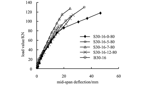
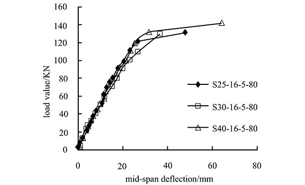
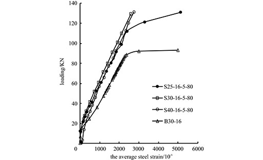
The load-deflection curve of the section in the middle of the test beam is shown in Figs. (6 and 7) shows the strain curves for the loads exerted on the internal non-prestressing steel bars (no. B30-16, S25-16-5-80, S30-16-5-80, and S40-16-5-80). As shown, the deflection-changing rule of the strengthened beams is similar to that of normal beams and can be divided into three phases.
Phase I: Elasticity
This phase extends from the beginning of loading to the initiation of cracking in the concrete. For the non-loading of strengthened beams in the test, the phase covers the period of loading until the second set of concrete cracks is formed. Early in the loading process, the load is small and the load-deflection relationship is linear. The deflection of the strengthened beams is similar to that of the normal beams. Beam deflection increases slowly, and the strain in the internal non-prestressing steel increases only slightly. The entire beam deforms elastically.
Phase II: Deformation with Cracks
This phase extends from the formation of cracks in the concrete to the yielding of the internal non-prestressing steel. With increases in the load, the concrete under tension gradually ceases to deform elastically, and the strain in the internal non-prestressing steel increases more than during Phase I. For a given load, the steel strain in the strengthened beam is less than that in the non-strengthened beam. The steel yield in the strengthened beam happens at a higher load than in the non-strengthened beam. This indicates that constraint by the CFRP tendons can improve the loading capacity of the internal non-prestressing steel within reinforced concrete. The load-deflection curve presents a turning point, the flexural rigidity of the beam decreases, the deflection growth rate is high, and the flexural rigidity after crack formation is greater than that in a non-strengthened beam.
Phase III: Breakage
This phase extends from the yielding of the internal non-prestressing steel to the breakage of the beam. After the internal steel yields, further increases in the load cause the strain of the steel to increase sharply. In this regime, the loading capacity is mainly provided by the CFRP tendons. Another turning point appears in the load-deflection curve. The flexural rigidity of the beam decreases further, the deflection increases rapidly, and the crack widths exceed the ultimate criterion; finally, the beam fails.
2.2. Test Beam Failure Mode
The failures of all of the test beams can be summarized in that, after the yielding of the internal non-prestressing steel, the widest vertical cracks are 2.0 mm wide. The final failure manifests itself as the simultaneous breakage of the CFRP tendons and the stressed concrete. The failure mode of the test beams is shown in Figs. (8 and 9).
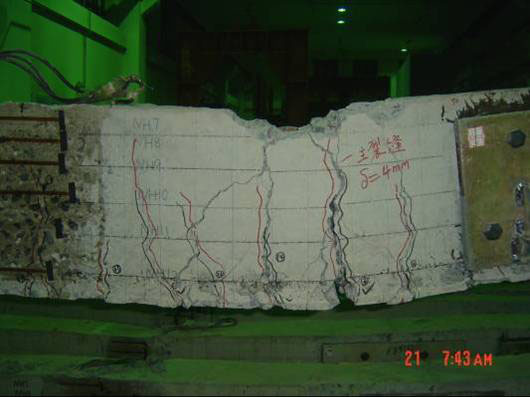
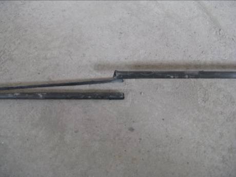
In the experiments, all of the test beams that experienced CFRP tendon failure sustained breakage of the CFRP tendons, rather than the unmooring of the anchor heads. The breakage always occurred between the middle of the span and the turning device. When CFRP tendon breakage occurred, the large punching shear of the CFRP tendons at both ends caused the anchors to split off, indicating that the design of the clamping pieces and anchor devices is reliable. The CFRP tendons at the turning devices did not suffer from wear or breakage, indicating that the selected bending radius is reasonable.
PS: B indicates non-reinforced beams; S indicates non-loading reinforced beams; D indicates loading reinforced beams. The first number after the letter represents the concrete grade; the second number is the diameter of internal non-prestressing steel bar. Parentheses indicate two layers of steel bars; the number in parentheses is the diameter of steel bars in the upper layer, while that outside the parentheses is the diameter of steel bars in the lower layer. The third number is the turning angle of the CFRP tendon; the fourth number represents the ratio between the pre-splitting test load before reinforcement and the value of Pu.
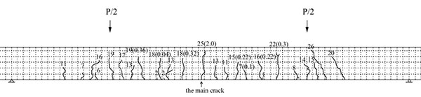
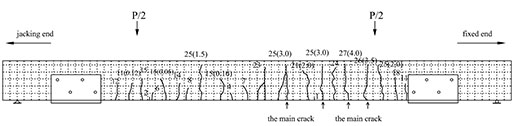
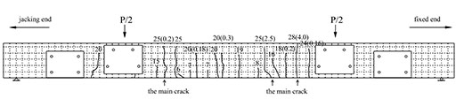
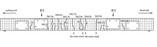
Fig. (10) shows the distribution of the beam cracks. The numbers in the figure are the crack heights in centimetres, while those in parentheses are the crack widths, again in centimetres. The dotted-line grids overlaying the cracks measure 50 mm × 50 mm (top edge 50 mm × 30 mm). According to the figure, the average crack intervals and widths of the strengthened beams are both smaller than those of the non-strengthened beams; the cracks of the strengthened beams are concentrated between the two turning devices. Because of the restriction imposed by the steel, few cracks occur at the anchoring and turning devices; all of the strengthened beams present bending failures that are typical of balanced-reinforcement beams. During the experiment, the widths of new cracks in the strengthened beams are significantly smaller than those in the non-strengthened beams; the cracks also develop more slowly. Overall, CFRP tendons demonstrate a remarkable ability to improve the anti-cracking properties of beams.
2.3. Strain Feature of Right Section
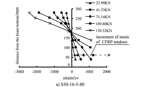
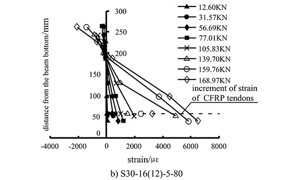
Fig. (11) depicts the distribution of measured strains in the mid-span sections of beams S30-16-5-80 and S30-16(12)-5-80. The increment in the CFRP tendon strain occurs 60 mm from the base of the beam. As shown in Fig. (11), before the beam splits, the average strain value changes linearly with the height. The deformations of the CFRP tendons and beams are linked; when the beam splits, the deformation of the beam still conforms to the behaviour of a beam with a planar cross-section. However, the strain in the CFRP tendons is smaller than that in the concrete at the bottom of the beam. This is because the strain in the CFRP tendons depends on the relative displacement of the two sections in the anchoring device. In the ultimate conditions, the average strain in the concrete in the mid-span section is distributed linearly up to the height of the beam. Therefore, when calculating the bending bearing capacity, the use of a planar cross-section should be assumed. The strain in the CFRP tendons is thus related to the deformation of the beams.
2.4. Analysis of Bending Bearing Capacity
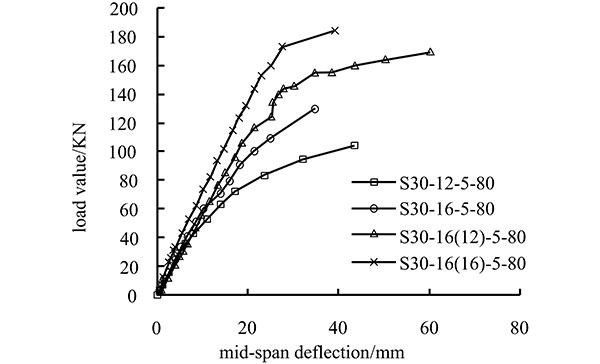
Fig. (6) shows the load-deflection curve for the loading of the strengthened beam with the factors including the concrete grade, turning angle of the CFRP tendons, reinforcement ratio of internal non-prestressing steel, and loading strengthening level of external prestressing CFRP tendons. The bending bearing capacities of the test beams are listed in Table 4.
| Beam Number | Measured concrete strength (MPa) |
Normal steel ρs(%) | Ultimate loading (kN) |
|---|---|---|---|
| B30-16 | 29.48 | 1.01 | 88.67 |
| S30-16-0-80 | 29.48 | 1.01 | 98.96 |
| S30-16-5-80 | 29.48 | 1.01 | 139.52 |
| S30-16-7-80 | 29.48 | 1.01 | 131.48 |
| S30-16-12-80 | 29.48 | 1.01 | 126.70 |
| S25-16-5-80 | 21.39 | 1.01 | 131.39 |
| S40-16-5-80 | 37.22 | 1.01 | 141.69 |
| S30-12-5-80 | 29.48 | 0.57 | 103.75 |
| S30-16(12)-5-80 | 29.48 | 1.90 | 171.14 |
| S30-16(16)-5-80 | 29.48 | 2.45 | 184.06 |
| D40-16-5-60 | 37.22 | 1.01 | 111.25 |
| D40-16-5-70 | 37.22 | 1.01 | 132.66 |
| D40-16-5-80 | 37.22 | 1.01 | 127.24 |
As listed in Table 4, compared with the non-strengthened beams, beams with external prestressing by CFRP tendons exhibit improved bending bearing capacities. With the same concrete grade and internal non-prestressing steel reinforcement ratio, the bending bearing capacity can be increased through the use of external tendons to 143–157%. Four factors influencing the bending bearing capacity of beams are analysed according to the data given in Fig. (6) and Table 4.
(1) Turning angle of external CFRP tendons
As shown in Table 4, with increases in the turning angles of the beams, the ultimate loading of the strengthened beams increases first, reaches a maximum, and then decreases. When the turning angle is 12°, the ultimate loading is 126.7 kN; when the turning angle is 5°, the ultimate loading is 139.52 kN. The difference is thus 12.82 kN. Therefore, every increase of 1° in the turning angle will lead to a 1.3% decrease in the bending bearing capacity. When the turning angle is larger than 10°, the bending bearing capacity of the beam degrades quickly. Therefore, the turning angle for the CFRP tendons should be 10° or less.
(2) Concrete strength
When comparing test beams with different concrete strengths, the ultimate loading of the C30 beam is larger than that of the C25 beam by 6.2%. The ultimate loading of the C40 beam is larger than that of the C30 beam by 1.6%. Therefore, increases in the concrete strength only slightly increase the ultimate bending bearing capacity. This is because the ultimate breakage first presents as the yielding of the internal non-prestressing steel, which results in rapid movement of the upper neutral axis and increases in the deflection. The strain of the CFRP tendon increases rapidly, which leads to splitting of the beam.
(3) Reinforcement ratio of internal non-prestressing steel
Increases in the reinforcement ratio cause increases in the bending bearing capacity of strengthened beams. Beams that have smaller reinforcement ratios exhibit up to 34.5% larger ultimate loads and higher bending capacities. The experimental results also show that, for beams with larger reinforcement ratios, the ultimate loading increases by 7%, the strengthening provided by external prestressing CFRP tendons has little effect. Therefore, it is not necessary to increase the number of CFRP tendons in order to improve the bending bearing capacity of the concrete beams. The number of CFRP tendons used with internally reinforced beams should therefore be reasonable and suitable.
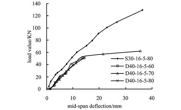
(4) Loading strengthening level of external prestressing CFRP tendons
According to Table 4, loading strengthening has an effect on the bending bearing capacity of beams. For beams of equal concrete strength, higher strengthening levels correlate to smaller increases in the bending bearing capacity, dropping from 19.2% to 14.4%. In applications involving the strengthening of old bridges, the influence of the loading strengthening level should be considered.
Overall, smaller turning angles of the external CFRP tendons, lower concrete strength, smaller reinforcement ratios of internal non-prestressing steel, and lower loading strengthening levels are correlated to remarkable improvements in the bending bearing capacity of beams. The strengthened beam S30-16-5-80 has these features, so the effects on the behaviour of the beam are obvious and typical.
When the size of concrete structures varies, the scale effects of materials and structures can influence the experimental results. If the devices were to be applied to larger beams, it would be necessary to undertake further research on the scale effects of beam tendons.
2.5. Analysis of Ductility
Because traditional ductility indicators are not suitable for CFRP tendon structures, we introduce the work of Zou [18] in this study and use the ductility indicators for fibre-reinforced plastic (FRP) tendons used to prestress concrete beams as the ductility indicators for the CFRP tendons. The ductility indicator is the ratio of the arithmetic product of the bending moment and the deflection at breaking, divided by the arithmetic product of the bending moment and the deflection at splitting:
 |
(1) |
The calculated ductility indicators of the test beams (without loading strengthened beams) are listed in Table 5. As shown, the ductility indicators of the strengthened beams are smaller than those of the non-strengthened beams. The ductility decreases with an increase in the concrete strength and an increase in the internal non-prestressing steel reinforcement ratio. The turning angle of the CFRP tendons has little influence on the ductility.
| No. | Deflection(mm) | Bending moment(KN.m) | Z | ||
|---|---|---|---|---|---|
| Δcr | Δu | Mcr | Mu | ||
| B30-16 | 2.0 | 17.0 | 7.2 | 36.6 | 43.1 |
| S30-16-0-80 | 6.8 | 47.0 | 15.3 | 40.8 | 18.5 |
| S30-16-5-80 | 6.6 | 35.5 | 16.9 | 57.6 | 18.3 |
| S30-16-7-80 | 4.7 | 25.0 | 14.9 | 54.2 | 19.4 |
| S30-16-12-80 | 5.0 | 27.0 | 15.3 | 52.3 | 18.5 |
| S25-16-5-80 | 6.0 | 48.0 | 16.5 | 54.2 | 26.3 |
| S40-16-5-80 | 8.3 | 65.0 | 19.0 | 58.5 | 24.1 |
| S30-12-5-80 | 6.0 | 44.0 | 13.6 | 42.8 | 23.1 |
| S30-16(12)-5-80 | 9.0 | 57.0 | 23.6 | 70.6 | 18.9 |
| S30-16(16)-5-80 | 9.5 | 38.0 | 24.8 | 75.9 | 12.3 |
3. CALCULATION OF BEARING CAPACITY ON RIGHT SECTION OF BENDING STRUCTURE
For beams strengthened by an external prestress from CFRP tendons, the deformation of the CFRP tendons does not satisfy the assumption of a planar cross-section. Under loading, the stress increment of the CFRP tendons Δfps is determined by the overall deformation of the beam between the tendon anchor points. Simultaneously, deflections caused by the deformation of the beams can reduce the effective eccentricity of the CFRP tendons, thereby reducing the bending bearing capacity, which is a secondary effect. Therefore, when calculating the bending bearing capacity of strengthened beams, we should determine the stress sustained by the external prestressing CFRP tendons in the ultimate conditions and also consider the secondary effects.
3.1. Calculation of Stress Increment For CFRP Tendons
The stress sustained by the external prestressing CFRP tendons under the ultimate conditions can be expressed as:
 |
(2) |
The test results show that the bending bearing capacity of the strengthened beams approaches that of traditional concrete beams strengthened by external prestressing tendons. Based on this similarity, we introduced the analytical method used for traditional tendon-prestressed concrete beams [2], combined with the features of the tensioning anchoring devices used for the CFRP tendons. From this hybrid, we deduced the calculation of the stress borne by the CFRP tendons.
The assumptions for the calculation are as follows:
- After bending, the cross-section of the test beam (without CFRP tendons) remains planar;
- The tensile strength of the concrete after the beam has split is not considered;
- After the yielding of the internal non-prestressing steel, the curvature distribution of beams strengthened by external prestressing CFRP tendons is as shown in Fig. (12);
- The deformation of the tensioning anchoring devices and turning devices are not considered.
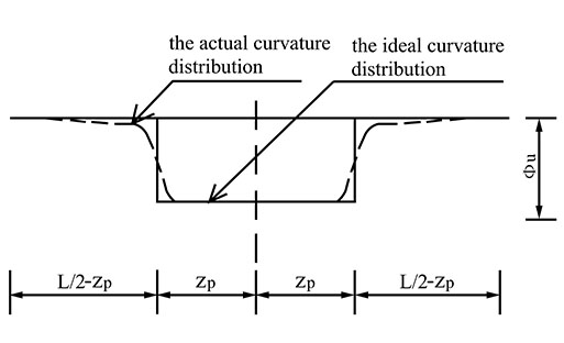
Under the ultimate conditions, the relationships between the ultimate curvature of the beam ϕu, ultimate turning angle at ends θu difference in deflection between the CFRP tendons and the mid-span section Δ and the length of the plastic hinge region 2Zp are as follows:
 |
(3) |
 |
(4) |
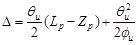 |
(5) |
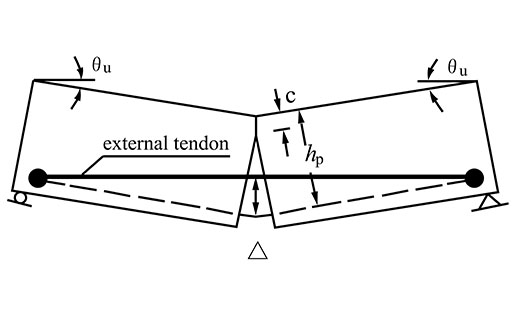
According to Fig. (13a), the elongation of a straight-line CFRP tendon in a strengthened beam in ultimate conditions is:
 |
(6) |
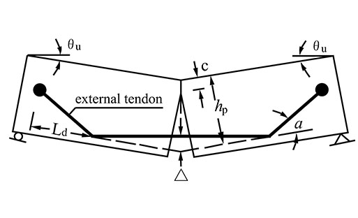
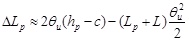
According to Fig. (13b), the elongation of a folded-line CFRP tendon in a strengthened beam under the ultimate conditions is:
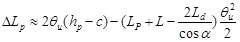 |
(7) |
Therefore, the stress increment in CFRP tendons is:
 |
(8) |
The length of the plastic hinge region of a concrete beam strengthened by external prestressing CFRP tendons (2Zp) is calculated by the formulas deduced by Bin [19]:
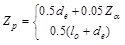 |
(9) |
The value of Zp is the larger of the two results obtained from Eq. (9).
The formula was obtained according to plastic hinge region theory and experimental results. It is suitable for beams with two-point symmetrical loading. The values obtained for the test beam deflection and CFRP tendon strain increment by using this formula are closer to the real values. There are two values for Zp but we take the larger of the two. The first formula is used to calculate the length of the plastic hinge region of the test beam when single-point loaded. The second formula is used to calculate the length of the plastic hinge region of the bent structures.
3.2. Calculation of Bending Bearing Capacity in Right Section
When the external prestressing CFRP tendon fps value under the ultimate conditions is known, a diagram for the bending bearing capacity of a beam strengthened by external prestressing CFRP tendons can be determined, as shown in Fig. (14).
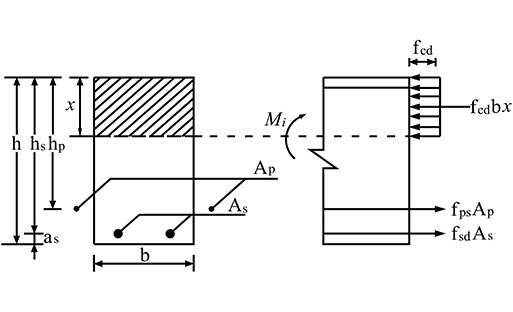
According to the equation:
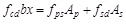 |
(10) |
To determine the moment of the working point in the concrete compressive zone, the bending bearing capacity of beams strengthened by external prestressing with the secondary effect Mdu should be considered; the effect is calculated as follows:
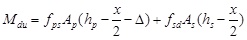 |
(11) |
If the secondary effect is neglected, the bending bearing capacity in the right section Mdu can be calculated as:
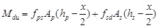 |
(12) |
In (12), to ensure that the yield strength of internal non-prestressing steel under the ultimate conditions after strengthening is considered, x should satisfy the conditions of
 , which includes cases of plastic failure.
3.3. Analysis and Comparison of Calculated and Measured Values of Bending Bearing Capacity of Test Beams
Using the above equations, we calculated the value of the ultimate bending moment of the test beams both with and without a secondary effect; the results are listed in Table 6. In the table, we can see that beam S30-16-0-80 splits earlier than expected because of the damage to the CFRP tendons. The ultimate bending bearing capacity of this sample is very small, and therefore this sample was left out of the analysis and comparison.
| Teat beams number | Measured value(KN.m) | with secondary effect | without secondary effect | ||
|---|---|---|---|---|---|
| calculated value(KN.m) | calculated value/measured value | calculated value(KN.m) | calculated value/measured value | ||
| S30-16-0-80 | 40.8 | 49.66 | - | 50.38 | - |
| S30-16-5-80 | 57.6 | 50.58 | 0.878 | 51.35 | 0.891 |
| S30-16-7-80 | 54.2 | 51.58 | 0.952 | 52.38 | 0.966 |
| S30-16-12-80 | 52.3 | 49.13 | 0.939 | 49.83 | 0.953 |
| S25-16-5-80 | 54.2 | 44.93 | 0.829 | 45.37 | 0.837 |
| S40-16-5-80 | 58.5 | 52.09 | 0.890 | 52.99 | 0.906 |
| S30-12-5-80 | 42.8 | 34.35 | 0.803 | 35.47 | 0.829 |
| S30-16(12)-5-80 | 70.6 | 64.06 | 0.907 | 64.60 | 0.915 |
| S30-16(16)-5-80 | 75.9 | 73.46 | 0.968 | 73.88 | 0.973 |
| D40-16-5-60 | 45.9 | 48.34 | 1.053 | 49.35 | 1.075 |
| D40-16-5-70 | 54.7 | 50.95 | 0.931 | 51.92 | 0.949 |
| D40-16-5-80 | 52.5 | 47.05 | 0.896 | 48.00 | 0.914 |
According to the table, the measured and calculated values for the bending moment coincide well. When considering the secondary effects, the average ratio between the calculated and measured value is 0.913; without secondary effects, the average ratio is 0.928. The latter is 1.5% greater than the former; therefore, the equations for the bending bearing capacity of beams strengthened by external prestressing that are introduced in this study can provide good reference values. For small beam spans, it is feasible to ignore the secondary effects; the proposed formulas can satisfy the required levels of precision in actual engineering projects.
CONCLUSION
In this study, we poured 13 reinforced concrete beams with rectangular cross sections and strengthened with external CFRP tendons. In static load testing of the simply supported beams, we studied the flexural properties of the strengthened concrete beams, and then discussed the calculation of the bending bearing capacity on the right section of the reinforced beams. There are only 13 test beams, and the findings and conclusions are limited because the strengthening and elasticity modulus of concrete, steel, and CFRP tendons will vary. Using the limited studied samples, we acquired the following conclusions:
- The deflection-changing rule of strengthened beams is similar to that of normal beams; the average strain of the beam still conforms to the behaviour of a beam with a planar cross-section; external prestressing CFRP tendons can improve the anti-cracking properties, stiffness, and flexural properties of concrete beams.
- When the turning angle exceeds 10°, the bending bearing capacity of the beam quickly degrades; increases in the concrete strength only slightly increase the ultimate bending bearing capacity; for beams with larger reinforcement ratios, the strengthening provided by external prestressing CFRP tendons has little effect. The bending bearing capacity of a reinforced beams increases with an increase in the reinforcement. The higher the strengthening level, the less the bending bearing capacity increases.
- The ductility decreases with the concrete strength and increases in the internal non-prestressing steel reinforcement ratio. The turning angle of the CFRP tendons has little influence on the ductility.
- The equations of bending bearing capacity of the external prestressing strengthened beams are deduced in the plastic hinge region. Without any secondary effect, the equations for the bending bearing capacity of beams strengthened by external prestressing CFRP tendons, as introduced in this study, can provide good reference values. For small beam spans, it is feasible to ignore the secondary effect; the proposed formulas can satisfy the required levels of precision in actual engineering projects.
NOTATION USED IN FIGURES AND EQUATIONS
CONFLICT OF INTEREST
The authors confirm that this article content has no conflict of interest.
ACKNOWLEDGEMENTS
Declared none.

