All published articles of this journal are available on ScienceDirect.
The Investigation of Stability on Slopes Utilizing Reinforcement Gabion Walls and Concrete Piles for Mitigating Landslide Disasters
Abstract
Introduction
Landslides frequently occur along roads crossing mountainous terrain during the rainy season, posing a significant risk of severe disruption to land transportation routes. Efficient and accurate resolutions are essential in managing landslides to facilitate immediate transportation recovery, such as gabion walls and pile installation.
Aim
This article aimed to evaluate the effect of installing gabions and piles for safety measures on the stability of slope landslides. The analysis of slope stability was performed utilizing the Plaxis 2D software. For reinforced slopes, the Safety Factor (SF) value utilized as a benchmark for evaluating slope stability was SF ≥ 1.5.
Methods
An assessment of the stability of the slope was conducted under three conditions: its original state, after reinforcement with gabions, and after the integration of gabions with mini piles. The dimensions of the gabion setting, as determined by the L-W-H notation (length-width- height), were 2 m x 1m x 0.5 m and 1 m x 2 m x 0.5 m. The pile was designed to be 2.5 m long at the gabion's end. The analysis was conducted at 45°, 60°, 70°, and 90° slopes.
Results
Based on the results of slope stability calculations, an SF = 1.11 was determined under no reinforcement conditions. By applying reinforced gabion walls measuring 2 m in width combined with mini piles at a 45° slope, the best SF was achieved, which was 2.58.
Conclusion
Given the comparable topographical circumstances, it is expected that the outcomes of this analysis on slope stability will be applicable in mitigating the occurrence of landslides.
1. INTRODUCTION
The movement of soil or rock from one location to another in a vertical, horizontal, or sloping direction is known as a landslide. Landslides have the potential to be classified as natural disasters and they can be caused by two primary sources: natural factors and trigger events [1-3]. Natural factors, such as the topography or slope of the ground, the hydrological conditions or water content in the soil, and the structure and strength of the underlying soil layers and rocks, all have an impact on the occurrence of landslides [4-7]. In slope engineering, water absorption causes soil swelling and a decrease and loss of strength. As the slope loses water, the soil shrinks, causing fractures. Repeated fluctuations in volume loosen the swelling soil and generate unbalanced fissures, allowing additional soil to erode [8-11]. Furthermore, the instability of a slope can arise from internal or external influences, leading to collapse either by diminishing the shear strength of the slope material or by adding shear stress to the slope [12-14]. The primary triggers for landslides include seismic activity or soil displacement, excessive precipitation, construction activities that impose additional load on slopes, and excavation at the base of the slope. Unstable slopes pose significant hazards to civil projects and the surrounding environment [15-17]. Hence, the analysis of slope stability is crucial in the early stages of building design and in areas with conditions that may lead to landslides [18, 19]. The assessment of slope stability is determined by quantifying the amount of the slope safety factor [8, 20, 21]. Several remedial proce dures are implemented before and after construction to mitigate the effects of slope failure. These approaches can be categorized into four main classes: geometric modification, drainage management, slope reinforcement, and retaining structures. Geometric adjustment changes the slope shape to lower the failure risk. Drainage management controls water flow to prevent slope failure from saturation and erosion. Slope reinforcement methods include soil nailing, rock bolting, and geosynthetic mate rials, like geogrids and geotextiles. Retaining structures stabilize the slope and prevent mass movement. The construction can be gabions, piles, soil nails, or retaining walls [22, 23].
The road routes connecting cities within the Aceh Province region, particularly in the Central-West-South area, typically traverse mountainous and uneven terrain, including mountains that are susceptible to landslides. The presence of hills and heavy rainfall during specific periods, such as November to February, create topographic circumstances that make various areas susceptible to landslides. An instance of landslides, among various other problems, occurred on the Bireuen-Takengon cross-road segment. This event resulted in the collapse of nearly the whole road, as depicted in Fig. (1). Due to this catastrophe, the transportation route from Bireuen to Takengon, namely at Km 85 in Jamur Ujung Village, Wih Pesam District, Bener Meriah Regency, has entirely collapsed. The disaster has also caused disruptions in the distribution of essential community necessities along the Bireun-Bener Meriah-Takengon route in both directions.
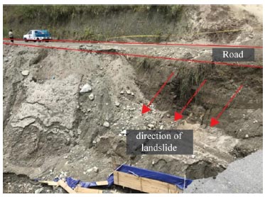
The Bireuen-Takengon cross-road segment’s experience of a landslide disaster, resulting in the collapse of a major section of the road.
Presently, slope stability studies are gaining the interest of researchers due to their growing understanding of the consequences of slope collapse on human life and infrastructure development [14, 24-26]. Extensive slope stability investigations have been conducted worldwide, resulting in improved comprehension of failure causes, failure processes, analysis techniques, and potential mitigation measures. According to previous studies [18, 27, 28], a safety factor value of SF ≥ 1.5 is usually utilized in standard designs to evaluate the safety factor in slope stability analysis. It is essential to maintain the safety of the slope design and prevent any unforeseen issues during investigation and construction, such as inaccurate data, errors in analysis, substandard workmanship, and inadequate field supervision [29, 30]. Moreover, an effective method for mitigating landslides is the implementation of walls on the slope as a means of reinforcement, hence enhancing the safety factor of slope stability [31-33]. Utilization of gabions in the field is typically straightforward and does not require special skills [34, 35]. Therefore, examination and discussion of the extent to which the use of gabions can raise the Safety Factor (SF) under various geometric slope circumstances in this study are conducted. The slope safety factors are calculated using the finite element method, utilizing Plaxis 2D. The software enables efficient and rapid analysis, providing comprehensive data that enhance the understanding of slope stability. To determine and evaluate the safety factors for slopes utilizing gabions, a comprehensive analysis model has been developed. This model incorporates several procedures, including the modification of slope angle variables, the alteration of gabion arrangements, and the integration of concrete minipiles at the bottom of the slope. Through the analysis of safety factors in multiple model variations, engineers can gain knowledge about the most efficient and ideal circumstances for practical application.
2. MATERIALS AND METHODS
The investigation was conducted at the location of Bireuen-Takengon Road, particularly in Jamur Ujung Village, Wih Pesam District, Bener Meriah Regency, Aceh Province. The research location is situated at the geographical coordinates of 4°42'24.08” N and 96°49'15.59” E. Additionally, it is located at an elevation of 1.227 meters above the sea level. The study encompassed the setting up of a field survey, laboratory experimentation, and software analysis. The field survey was carried out through the collection of soil samples and the use of GPS technology. The main quantitative data were acquired by laboratory investigation of soil samples to ascertain the material properties and input specifications for software analysis. Secondary data were obtained by performing a literature review and interacting with the local community.
There were two types of samples used in sampling: undisturbed and disturbed. Undisturbed samples of unsaturated soil conditions were collected by the test pit method. This method involves collecting samples using metal tubes at depths of 2 m and 5 m. This is because visual observation indicates that the soil layer between 1 and 4 meters has a similar soil type, as does the layer between 5 and 6 meters. Therefore, there are two distinct soil layers. To ensure consistency, both sides of the tube are coated with wax. This is done to maintain the soil's water content until the test is conducted. Disrupted samples of unsaturated soil conditions were also collected at depths of 2 m and 5 m and promptly placed into soil sacks. The collected data served as input for slope stability analysis with the Plaxis 8.6 version. Table 1 shows the soil parameters used in this study.
The soil parameters were utilized as input data to derive various calculation outcomes for reinforcing retaining walls along the research area. Soil volume weight (γ), cohesiveness (c), and angle of friction in the soil (φ) were the data utilized for slope stability analysis using Plaxis. These values were derived from laboratory test results on soil samples at the study site. Additionally, relevant data, such as the dilatancy angle (Ѱ), Poisson’s ratio (υ), soil permeability coefficient (kx, ky), and soil elastic modulus (E) were sourced from the available literature, specifically based on laboratory test results corresponding to the particular soil type. Several analysis variables were determined and entered into the Plaxis program to generate the slope geometric model applied to stability analysis. The inspection of slope stability was conducted under two conditions: the original state and the strengthened state, as can be seen in Fig. (2). The original state involved inputting the initial geometric conditions before slope collapse, derived from empirical data. Adding gabion reinforcement and a combination of gabions and concrete minipiles at the base of the slope constituted the strengthening condition.
Additionally, the study examined slope stability reinforcement through the analysis of three scenarios: without the use of retaining walls, with the use of retaining gabion walls, and with the use of gabion walls in combination with concrete minipiles. The construction of gabion walls with a combination of concrete minipiles was planned based on the considerations specified in Table 2. Before determining the proper position of the gabion walls for soil retention, it is essential to evaluate the extent of the landslide area on the slope. The location of the soil-retaining gabion wall, in conjunction with the positioning of concrete minipiles, may affect the Safety Factor (SF) of the slope. If the SF satisfies the minimum criteria, the option of utilizing a soil-retaining gabion wall combined with minipiles becomes feasible for installation. If multiple positions fulfill the slope stability safety factor require- ments, the placement that is most efficient and cost-effective is preferred.
| Soil Parameter | Layer 1 | Layer 2 | Backfill Material | Gabion | Unit |
|---|---|---|---|---|---|
| Sandy Silt | Clayey Silt | Clayey Sand | |||
| AASHTO classification | A-4 | A-4 | A-7 | - | - |
| USCS classification | ML | OL | MH | - | - |
| Type of behavior | Drained | Drained | Drained | Drained | - |
| Dry soil weight (ɣdry) | 11.164 | 10.438 | 12.625 | 25.000 | kN/m3 |
| Wet soil weight (ɣwet) | 16.363 | 16.245 | 16.873 | 26.672 | kN/m3 |
| Horizontal permeability (kx) | 0.0864 | 0.00864 | 0.0864 | 86.4 | m/day |
| Vertical permeability (ky) | 0.0864 | 0.00864 | 0.0864 | 86.4 | m/day |
| Young’s modulus (Eref) | 9,810 | 19,620 | 29,430 | 1,373,400 | kN/m2 |
| Poisson’s ratio (v) | 0.3 | 0.3 | 0.3 | 0.4 | - |
| Cohesion (c) | 7.85 | 8.83 | 34.34 | 17.7 | kN/m2 |
| Friction angle (ϕ) | 33.3 | 35.7 | 25.8 | 45 | ° |
| Dilatancy angle (Ѱ) | 3.3 | 5.7 | 0 | 15 | ° |
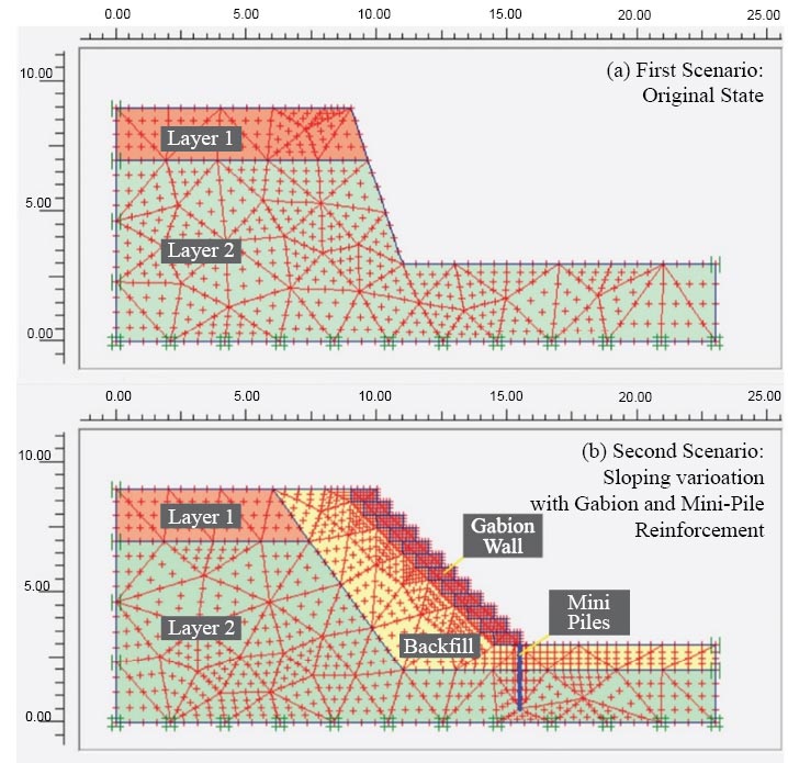
Scenarios of gabion wall and minipile design for slope reinforcement.
| No. | Variable | Remarks |
|---|---|---|
| 1. | Gabions dimension | Dimension 2m x 1m x 0.5m (length x width x height) |
| Dimension 1m x 2m x 0.5m (length x width x height) |
||
| 2. | Slope angle | 45º |
| 60˚ | ||
| 70º | ||
| 90º | ||
| 3. | Minipile dimension | Diameter = 0.2 m Length = 2.5 m |
3. RESULTS AND DISCUSSION
Field observations from several viewpoints indicated the landslide to be of the rotating type, characterized by the movement of soil and rock masses along a concave-shaped sliding plane. The research input from the Plaxis analysis, depicted in Fig. (3), revealed the geometry of the landslide area to closely resemble the patterns observed in the field. Based on the results, the SF for an unreinforced slope was 1.11, indicating an unstable slope. Furthermore, Fig. (4) displays the results of the Plaxis analysis, specifically the slope with reinforcement of gabions and concrete minipiles.
Table 3 displays the quantitative effects of the gabion arrangement as well as the combined effect of gabions with concrete minipiles on the slope safety factor. The computation of the slope safety factor revealed the SF in the no-reinforcement state to be SF = 1.11, indicating landslide events aligning with the actual conditions on the site. Furthermore, the slope model with reinforcement yielded SF calculation results that all exceeded 1.5, indicating stable slope conditions. This condition was present on slopes that had reinforcement at all angles, except for slopes with a 90-degree angle when the SF was less than 1.5.
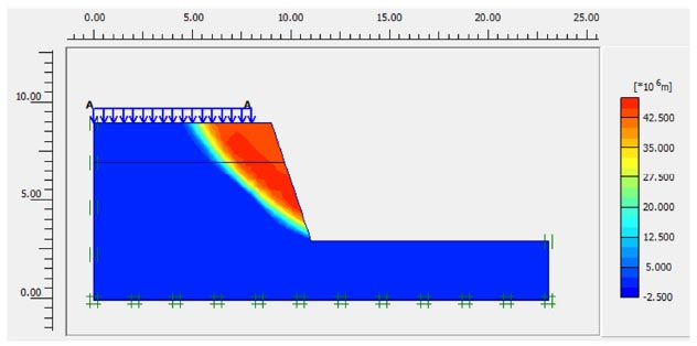
Unreinforced slope results from the plaxis analysis.
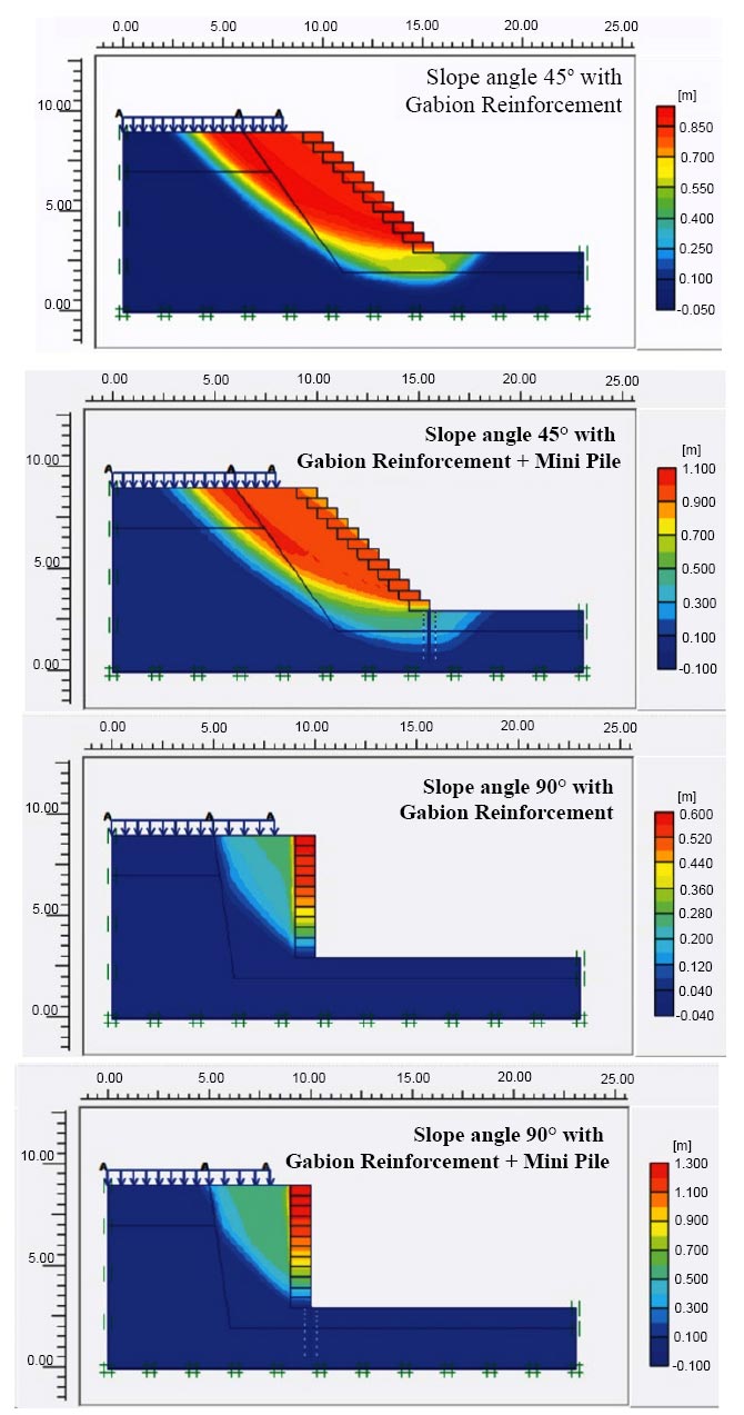
Slope results with reinforcement of gabions and concrete minipiles from the plaxis analysis.
| No. | Gabion Dimension L x W x H |
Minipileile | Safety Factor | |||
|---|---|---|---|---|---|---|
| Slope Angle | ||||||
| 45o | 60o | 70o | 90o | |||
| 1 | 2x1x0.5 m | With minipile | 2.24 | 1.89 | 1.73 | 1.26 |
| 2 | 1x2x0.5 m | With minipile | 2.58 | 2.23 | 1.91 | 1.46 |
| 3 | 2x1x0.5 m | No minipile | 2.20 | 1.79 | 1.53 | 1.18 |
| 4 | 1x2x0.5 m | No minipile | 2.57 | 2.21 | 1.88 | 1.31 |
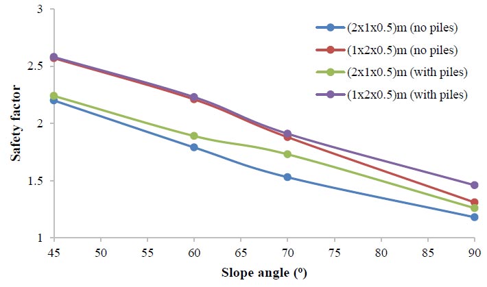
Relationship among the gabion, minipiles, and the safety factor.
Fig. (5) plots the findings of the analysis related to the effects of concrete minipiles on the combination model incorporating gabions. The results indicated that the utilization of minipiles affected the safety factor of the slope. In contrast to the strengthening model that solely employed gabions, enhancing the safety factor of the slope with concrete minipiles was possible when gabions were utilized in conjunction with minipiles. Additionally, as the angle of the slope decreased, the safety factor increased, specifically SF > 1.5. Conversely, an increase in slope angle resulted in a corresponding reduction in the slope’s safety factor (SF < 1.5), indicating the slope to no longer be secure even at a 90-degree angle.
In addition, as presented in Fig. (5), the study determined the influence of the slope angle on the slope safety factor. A decrease in the slope angle led to an increase in the safety factor. Conversely, when the slope angle increased, the safety factor decreased. At a slope angle of 90 degrees, the slope safety factor was less than 1.5, indicating the slope to no longer be safe. Additionally, combining gabions with concrete minipiles could enhance the safety factor of the slope above the strengthening procedure that only relied on gabions. The analytical results indicated that the gabion arrangement with dimensions of L-W-H (1x2x0.5) m presented a higher safety factor in comparison to the L-W-H (2x1x0.5) m model. This demonstrated that a gabion with a wider width was capable of withstanding larger external forces. Horizontal (lateral) force is one of the movements that occur in landslides. Hence, by increasing the width (W dimension) of the gabion, the length of the shear plane between the gabion's base and the ground may also grow. Consequently, the shear force that opposes the lateral movement would be greater, thus enhancing the slope safety factor. Based on the assessment results of an increase in slope SF, it can be inferred that the variables of the L-W-H gabion arrangement model had a greater influence on enhancing SF compared to the influence of the minipile combination model. The effect of the gabion arrangement resulted in a significant increase in the safety factor, compared to the improvement obtained with the combination of concrete minipiles. The analysis revealed that the gabion arrangement model variables exhibited greater effectiveness compared to the minipile combination model variables. The potential shape of the slope failure line in the analytical slope model was believed to have minimal effect on the increase of the safety factor for slope stability.
CONCLUSION
According to the results of the slope stability investigation conducted at the site of the landslide study, the following assumptions were made:
- The landslide that occurred in the research area was of the rotational type. In addition, the determined safety factor for the no-reinforcement conditions was 1.11, indicating the landslides to frequently occur in the region.
- The use of reinforcement through a gabion structure and a combination structure consisting of a concrete minipile could increase the safety factor across all slope angles, up to 70 degrees. Hence, to perform reinforcement using gabions, it was essential to restrict the inclination of the slope to a maximum of 70 degrees.
- The analytical results indicated the inclination of the slope to have a significant impact on its stability. That is, the lower the slope angle (sloping), the safer the slope. In all strengthening model settings, when the slope angle was 90˚, the SF was less than 1.5, indicating that it failed to meet the slope safety standards.
- The model with gabion reinforcement with concrete minipiles and a 45-degree slope measuring length (L) x width (W) x height (H) = 1x2x0.5 m yielded the highest safety factor, i.e., 2.58.
- The study also showed the variables in the L-W-H gabion arrangement model to have a greater effect on increasing the slope safety factor than the variables in the concrete minipile combination model. This demonstrated the variables of the gabion arrangement model to be more efficient than the variables of the concrete minipile combination model.
- Additional information on the geological and hydrological characteristics of the region, the economic feasibility and construction challenges associated with implementing gabion walls and minipiles in real-world scenarios, as well as the long-term performance and durability of the proposed reinforcement methods, should be taken into consideration in the future to make the analysis more comprehensive.
AUTHORS’ CONTRIBUTION
It is hereby acknowledged that all authors have accepted responsibility for the manuscript's content and consented to itssubmission. They have meticulously reviewed all results and unanimously approved the final version of the manuscript.


