All published articles of this journal are available on ScienceDirect.
Experimental Study on In-plane Stiffness of Track in a Turnout of the Railway in Vietnam
Abstract
Aims:
This study aims to determine the in-plane stiffness of the track in a turnout of the railway in Vietnam.
Background:
Track stiffness is a basic parameter of railway tracks that influences the bearing capacity of the track, the dynamic behavior of passing vehicles, the quality of track geometry, and the life of track components.
Objective:
The objective of this research is to determine the in-plane stiffness of the track based on substructure modulus, and rail pad stiffness at a track section in a turnout.
Methods:
Various tests which included the field tests of the substructure modulus, and rail pad stiffness tests in the laboratory were done. Substructure modulus was investigated at ten locations in the field. Rail pad stiffness was tested with five samples in the laboratory. In-plane stiffness of the track was calculated through substructure modulus and rail pad stiffness. The finite element method was used to evaluate the bearing capacity of bearings with different in-plane stiffness values.
Results:
Based on the results obtained, the substructure modulus was from 0.49 N/mm3 to 1.48 N/mm3. The rail pad stiffness is from 32.99 kN/mm to 34.92 kN/mm. These results are used to calculate the in-plane stiffness of the track. The in-plane stiffness of a track section in a turnout in Vietnam is from 25.18 kN/mm to 30.19 kN/mm. According to the finite element method, it is possible to determine the maximum value of forces transmission to the supports from 37.743 kN to 38.989 kN corresponding to the above stiffness values with the axle load of train 14 tons and rail P60.
Conclusion:
The stiffness of the supporting is proportional to the value of the force transmitted to the supporting. This study clearly showed that the substructure (soil and ballast) properties had the most impact on the total in-plane stiffness of the track. The results will be a tool for the track maintenance engineer to implement correct maintenance activities.
1. INTRODUCTION
The stiffness of the track is an important parameter in railway track engineering, both from a design and maintenance point of view. Many research works and surveys on track stiffness have been implemented over the years [1-6]. However, understanding of track stiffness and its effect on track performance is not yet complete.
The simplest representation of a continuous elastic foundation is the Winkler foundation model. In this model, the rail is represented by an infinite, uniform, Euler-Bernoulli beam supported by a continuous damped, elastic Winkler foundation. The effective mass of the sleepers is distributed uniformly and added to the mass of the rail [7-12]. In 1994, Vertical rail deflection under a specified load or change in load, track stiffness defined as the ratio of change in load to change in rail deflection, and track (foundation) modulus as defined by the beam-on-elastic-foundation model are given from tests on a heavy haul line by Ebersöhn and Selig [13]. In 2009, Burrow et al. studied and described the use of numerical models to assess the influence of track stiffness variations on the wheel/rail contact force of high-speed railways [14]. Fenander research on frequency-dependent stiffness and damping of rail pads [15]. Ilias studied the influence of rail pad stiffness on wheelset/track interaction and corrugation growth [16] and Thompson et al. studied the influence of the non-linear stiffness behavior of rail pads on the track component of rolling noise [17] in 1999. Some tests for Pandrol fastening were done in 2003 [18]. Some authors researched the effect of track stiffness on track performance [19-22]. Techniques for continuous measurement of vertical track stiffness have been developed in China [23], the United States of America [24], [25], and Sweden [26, 27]. Some other authors researched methods to measure the stiffness of the track [24, 28-33]. Foundation stiffness was studied by some authors [34-36]. In 2011, Xin and Gao researched on slab mat stiffness of high-speed railway in China [37]. The main factor that influences the longitudinal lengths of dynamic stresses of the subgrade surface is the stiffness of the concrete structure of the ballastless track [38]. Bodare et al. evaluated track stiffness with a vibrator for prediction of train-induced displacement on railway embankments [39]. J.Y. Choi., et al. study the evaluation of track support stiffness on the various track types in urban Transit [40] and research on the effect of track support stiffness for ballasted track to dynamic wheel-rail forces [41]. Fröhling et al. studied spatially varying stiffness, and the vertical dynamic response of a rail vehicle caused by track stiffness variations along the track and deterioration of railway track due to dynamic vehicle loading [42, 43]. Vertical track stiffness effect on the dynamic behaviour of track structure was studied by Moravcik in 2004 [44]. Na et al. studied experimental the variation of track stiffness between earthwork and bridge [45]. In addition, stiffness is an important input parameter in determining material strength. The steel strength was considered by Chandrasekaran and Srivastava [46, 47].
The different track stiffness along the track causes variations in vehicle-track interaction forces and leads to differential settlement and therefore differential track geometry deterioration and potential vibration problems. Therefore, the research on track stiffness is an important parameter in both railway design and maintenance. In this paper, the authors study the in-plane stiffness of the track of a railway section in a turnout location in Vietnam (1000 mm gauge), and track strength.
2. MATERIALS AND METHODS
2.1. Theoretical Basis for Calculating In-plane Stiffness of the Track
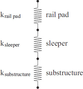
In the continuous beam model on elastic supports, the stiffness of the rail supporting represents the elastic characteristic of the supporting (Fig. 1).
Supporting stiffness is defined as the ratio between force and supporting deflection.
 |
(1) |
Where:
F is the force applied on the top surface of the rail supporting (kN)
y is the deflection of rail supporting under the effect of force (mm).
In this study, the supporting stiffness is considered the in-plane stiffness of the track. Modeling in-plane stiffness of the track is the stiffness total of the rail pad, sleeper, and substructure (Fig. 2).
Where:
ktotal is a coefficient of quasi elasticity (in-plane stiffness of the track) of the rail supporting (kN/mm);
ki is the stiffness of each layer (kN/mm);
krail pad is the stiffness of resilient rail pads in the track structure (kN/mm);
ksleeper is the stiffness of sleeper (kN/mm);
ksubstructure is the stiffness of substructure (kN/mm);
For prestressed concrete sleepers, ksleeper can be approximated = ∞, stiffness of resilient rail pad is determined in the laboratory. Stiffness of substructure according to the following formula:
 |
(2) |
Where:
C0 is the substructure modulus (kN/mm3), and C0 is determined from the field test.
l is sleeper length (mm)
b is sleeper width (mm)
Coefficient of quasi elasticity:
 |
(3) |
3. EXPERIMENTAL STUDY TO DETERMINATE IN-PLANE STIFFNESS OF THE TRACK
3.1. Modulus of Substructure
The track structure can be seen as a system consisting of rails that are elastically supported by means of rail pads by sleepers spaced at a fixed distance. The sleeper is supported by an elastic substructure consisting of ballast plus roadbed.
The experiments were implemented on the substructure in turnout with a full-scale model (Fig. 3).

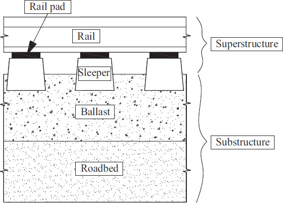
There are some methods that may be used to measure the in-plane stiffness of the track. The measurements are made at discrete intervals while standstill and the measurements are continuous while moving. Standstill measurements have been more widely used, often for research purposes.
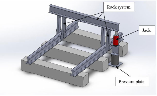
In this study, the measurements with discrete intervals while standstill were done. The authors research and produce an equipment system for measuring the modulus of the substructure under sleepers (Figs. 4 and 5). The loading is set through the jack and rack system. This force is transmitted to the substructure through the press plate. The dimensions of the pressing plate are 230 mm x 230 mm. Two strain gauges are installed to measure displacement relative to the applied load. Carry out continuous loading and record the corresponding displacements through strain gauges.
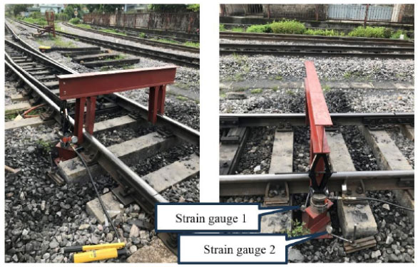
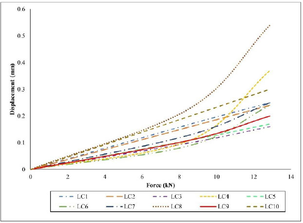
The survey of the elastic modulus of the substructure was carried out at 10 different locations at the turnout (From location 1(LC1) to location 10(LC10)). Preload is applied to reduce the effect of gaps and slips. When the load-displacement relationship graph is stable, data is collected. The load versus displacement curves under test load for the substructure are given in Fig. (6).
The displacement graph at positions is different due to moisture of the substructure, and the impact load of the previous trains. In some cases, low substructure stiffness values can also result from fouled or dirty ballast that prevents adequate support for the train load. This problem occurs especially when the ballast and roadbed deteriorate in the presence of water due to train-induced repeated loading. The resulting migration of fines into the ballast and subsequent formation of wet spots can lead to a reduction in the stiffness of the track support system.
Based on the relationship between load and displacement, we can determine the elastic modulus of the substructure as shown in Table 1.
The average substructure modulus is 1.05 N/mm3. We calculate for a sleeper with dimensions of length 1800 mm and width 230 mm. Based on Formula 2, the stiffness of the substructure such as in Table 2. Average of the substructure stiffness is 216.73 kN/mm. Substructure stiffness is very useful for investigations related to the bearing capacity of the track.
3.2. Stiffness of the Rail Pad
High stiffness leads to faster deterioration of the track and its components due to higher dynamic loads. In such cases, a method that may be used to reduce the stiffness is the installation of rail pads under the rail foot. The stiffness of the rail pad is also an important parameter in determining the overall stiffness of the track.
In order to determine the stiffness of the rail pads, in this study they were determined through laboratory tests (Fig. 7). Rail pads were made of rubber with a thickness of 10mm.
| No. | Location | Modulus of Substructure C0 (N/mm3) | No. | Location | Modulus of Substructure C0 (N/mm3) |
|---|---|---|---|---|---|
| 1 | LC1 | 1.02 | 6 | LC6 | 1.17 |
| 2 | LC2 | 1.01 | 7 | LC7 | 0.98 |
| 3 | LC3 | 1.48 | 8 | LC8 | 0.49 |
| 4 | LC4 | 0.93 | 9 | LC9 | 1.19 |
| 5 | LC5 | 1.41 | 10 | LC10 | 0.80 |
| No. | Location | Stiffness of the Substructure (kN/mm) | No. | Location | Stiffness of the Substructure (kN/mm) |
|---|---|---|---|---|---|
| 1 | LC1 | 210.37 | 6 | LC6 | 242.65 |
| 2 | LC2 | 209.59 | 7 | LC7 | 202.08 |
| 3 | LC3 | 305.65 | 8 | LC8 | 101.30 |
| 4 | LC4 | 191.77 | 9 | LC9 | 245.79 |
| 5 | LC5 | 292.20 | 10 | LC10 | 165.85 |
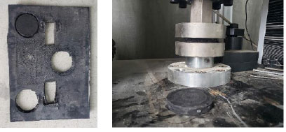
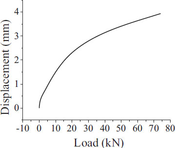
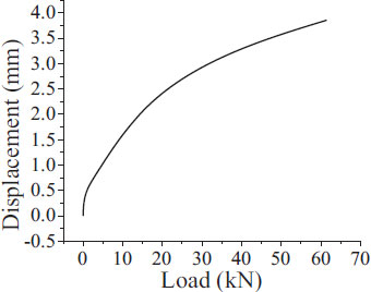
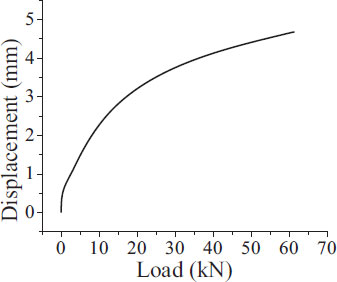
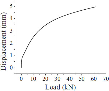
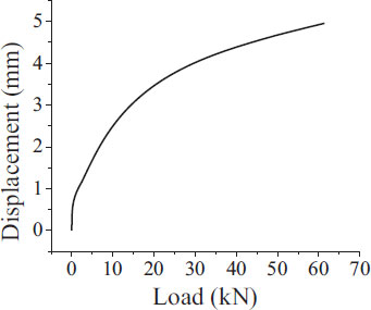
The test was done with 5 specimens of the rail pad. The results of the rail pad’s stiffness are shown in Table 3 and the rail pad’s corresponding displacement curves are shown in Figs. (8-12). The average rail pad’s stiffness is 33.50 kN/mm.
| Specimens | Stiffness of Rail Pad (kN/mm) |
|---|---|
| 1 | 34.92 |
| 2 | 33.28 |
| 3 | 33.14 |
| 4 | 33.18 |
| 5 | 32.99 |
3.3. In-plane Stiffness of the Track
Total track stiffness is important for track maintenance and design. Track stiffness determination provides useful specifications for the evaluation of track system safety and performance. The overall stiffness of the track is determined by the stiffness of the track's components. In this study, the track stiffness is determined through the stiffness of the rail pad and the stiffness of the substructure.
According to Formula 3, the in-plane stiffness of the track is shown in Table 4. The average in-plane stiffness of the track is 28.73 kN/mm. The results are consistent with references [48] and recommended that rail supporting static stiffness (for the track using concrete sleeper and rubber rail pad) should be taken as 22~42 kN/mm.
| No. | Location | In-plane Stiffness of the Track | Value (kN/mm) | No. | Location | In-plane Stiffness of the Track | Value (kN/mm) |
|---|---|---|---|---|---|---|---|
| 1 | LC1 | k1 | 28.90 | 6 | LC6 | k6 | 29.44 |
| 2 | LC2 | k2 | 28.88 | 7 | LC7 | k7 | 28.74 |
| 3 | LC3 | k3 | 30.19 | 8 | LC8 | k8 | 25.18 |
| 4 | LC4 | k4 | 28.52 | 9 | LC9 | k9 | 29.48 |
| 5 | LC5 | k5 | 30.06 | 10 | LC10 | k10 | 27.87 |

4. USING THE FINITE ELEMENT METHOD TO DETERMINATE FORCES ACTING ON THE RAIL SUPPORTING
4.1. Finite Element Method
When we consider the rail as a beam on elastic supports. Using the finite element method to discrete the rails into non-overlapping elements and satisfy the strain continuity and force balance conditions (Fig. 13).
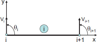
Considering a rail element as shown in Fig. (14).
We have the element's node displacement vector:
 |
(4) |
Since in direction vi, vi+1 has an elastic supporting of stiffness k, so we have an element stiffness matrix:
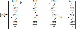 |
(5) |
Moving the load to the node. Node force of element:
 |
(6) |
Set up the overall hardness matrix K*. Solving the system of equations:
 |
(7) |
Displacement at nodes:
 |
(8) |
Substituting into the equation:
 |
(9) |
We have:
 |
(10) |
Determining the forces on rail supports Ri (Fig. 15):
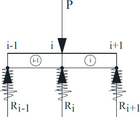
 |
(11) |
4.2. Calculating the Forces Transmitted on the Rail Supports by Finite Element Method
Using the P60 rail with the characteristics shown in Table 5. A section of rail with a length of 50m is divided into 80 elements. The length of each element is 0.625m. The distance between rail supportings is 0.625m. The locomotive has 4 axles with an axle load of 14 tons/axle. Calculating the force transmitted on the rail supporting with the values of in-plane stiffness of track in Table 4. Forces acting on the rail supports such as in Fig. (16). The value of the maximum force acting on the rail supporting is determined at the position under the wheel, and is shown in Table 6.
| Rail P60 | Specification | Symbol | Value |
| Elastic modulus | E | 210 GPa | |
| Inertia moment | I | 3217 cm4 |
| No. |
In-plane Stiffness of the Track (kN/mm) |
The Maximum Force Acting on the Rail Supports (kN) |
No. |
In-plane Stiffness of the Track (kN/mm) |
The Maximum Force Acting on the Rail Supports (kN) |
|---|---|---|---|---|---|
| 1 | 28.90 | 38.439 | 6 | 29.44 | 38.534 |
| 2 | 28.88 | 38,435 | 7 | 28.74 | 38.411 |
| 3 | 30.19 | 38.989 | 8 | 25.18 | 37.743 |
| 4 | 28.52 | 38.371 | 9 | 29.48 | 38.543 |
| 5 | 30.06 | 38.645 | 10 | 27.87 | 38.253 |
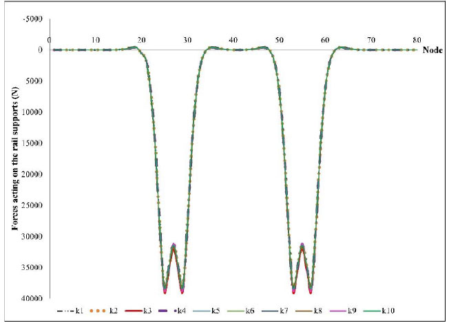
These results show that the stiffness of the rail support is proportional to the value of the force transmitted to the rail support. High stiffness increases the track's bearing capacity under the effect of train dynamic load. However, this will also cause large dynamic forces transmitted to the substructure. Therefore, research to choose the appropriate stiffness to create comfort for passengers and increase the life of the structure is necessary.
5. RESULTS
5.1. Calculating Track Strength
5.1.1. Calculating Rail Strength
The greatest dynamic bending tensile stress in the rail foot center can be determined from:
σmax = DAF.σmean = 71.94 N/mm2
The mean value of the rail bending stress follows from:
 |
Where:
DAF is a dynamic amplification factor,
 [11].
[11].
With t=3, φ=0.2, V=100 km/h, DAF=1.77.
L is characteristic length (cm),

a is the distance between rail supporting (cm), a = 62.5 cm
Wyf is section modulus, relative to the rail foot (cm3), Wyf = 377 cm3
5.2. Calculating Sleeper Strength
The maximum bearing force on a (single) discrete rail support due to the wheel load is:
Fmax = DAF.Fmean = 44.22 kN
 |
Contact pressure between rail and sleeper:
 |
Where:
F0 is the total pre-tensioning force of fastening on rail support (kN), F0 = 20 kN
Ars is the area of rail pad (cm2), Ars = 550 cm2.
6. DISCUSSION
The experimental results of the elastic modulus of a section of substructure in turnout show that the modulus of the substructure changes at different locations on the track. It depends on temperature, moisture content, dirty ballast, and applied preload of the track.
The higher the stiffness of the rail support is, the greater the force transmitted to the rail support is, which may cause disadvantageous effects on track components. Also, a particular problem is changes in-plane stiffness of the track along the railway track, which causes variations in wheel-rail interaction forces and leads to differential settlement and differential track geometry deterioration and potential vibration problems.
The stiffness of different components of the track structure, such as the rail pad and substructure, is nonlinear.
CONCLUSION
The actual in-plane stiffness of the track during operation will have different values. Accurate determination of the in-plane stiffness of the track helps the engineer to have the correct solution during track maintenance.
In-plane stiffness of the track is beneficial because it provides enough resistance to the track to the applied load and leads to a reduction in rail deflection, which reduces track deterioration. However, the high in-plane stiffness of the track results in increased forces acting on the supports, which can cause wear and fatigue of the track components. Therefore, determining and using the appropriate in-plane stiffness of the track has the effect of reducing the negative forces on components of the track under the effect of train load.
The authors performed in-plane stiffness of the track research for the track section in turnout in Vietnam. The results can be used to provide a design process. Besides, this research may also be used in calculating railway maintenance and repair. There are many in-plane stiffnesses for the railway, but in this article, the authors assess the in-plane stiffness of the track as supporting stiffness which includes rail pad and substructure (1,000 mm gauge).
With the stiffness values of the current road section at the turnout, the track strength is ensured during the operation of the train.
CONSENT FOR PUBLICATION
Not applicable.
AVAILABILITY OF DATA AND MATERIALS
The data and supportive information are available within the article.
FUNDING
This research is funded by the Ministry of Education and Training (MOET) under grant number B2022-GHA-07.
CONFLICT OF INTEREST
The authors declare no conflict of interest financial or otherwise.
ACKNOWLEDGEMENTS
Declared none.


