All published articles of this journal are available on ScienceDirect.

The Influence of the Material Properties on the Ultimate Behaviour of Aluminium H-shaped Beams
Authors Info & Affiliations
Abstract
Background:
In this paper, the influence of the Ramberg-Osgood exponent on the ultimate behaviour of the H-shaped (or I-shaped) aluminium beams subjected to non-uniform bending moment is investigated.
Methods:
In particular, the results of a wide parametric analysis recently carried out by the authors are herein exploited to point out the influence of the material properties. The flange slenderness, the flange-to-web slenderness ratio, and the non-dimensional shear length, accounting for the moment gradient, are the main non-dimensional parameters governing the ultimate resistance and the rotation capacity of H-shaped aluminium beams.
Results:
The influence of these parameters was investigated considering four different materials covering both low yielding-high hardening alloys and high yielding-low hardening alloys, which are characterised by significant differences in the values of the Ramberg-Osgood exponent of the stress-strain constitutive law of the material.
Conclusion:
Finally, empirical formulations for predicting the non-dimensional ultimate flexural strength and the plastic rotation capacity of H-section aluminium beams under moment gradient have been provided as a function of the Ramberg-Osgood exponent and all the above non-dimensional parameters.
1. INTRODUCTION
The success of aluminium alloys as constructional material in civil engineering structural applications is based on some prerequisites. They are connected with the physical and mechanical properties, the production process, and technological features. In particular, the main properties of this material are: the lightness: its specific weight is 2700 kg/m3, which is equal to one-third that of steel; the corrosion resistance: (except for some specific alloys) thanks to the formation of a thin inert aluminium oxide film, which blocks further oxidation; the functionality of the structural shapes: due to the extrusion fabrication process, allowing the design of tailor-made shapes for specific applications, and the favourable life-cycle cost, which is calculated as the sum of the initial cost of the product, the cost of operating and maintaining and the cost of disposing or recycling it after its life. However, aluminium alloys are also characterized by some structural disadvantages, especially when the material is loaded in compression. In fact, because of the small value of Young’s modulus, the instability phenomenon is more likely to occur than in steel structures; besides, the increase of the deformability gives rise to additional drawbacks in checking serviceability limit states. Moreover, the aluminium structures are more sensitive to thermal variations because their thermal coefficient is twice of steel.The structural applications’ best valorising aluminium alloy property is long-span structures. These structures are located in a corrosive or humid environment and in inaccessible places far from the fabrication shop [1, 2]. Some aluminium alloys have low-yielding and high hardening characteristics that make these materials suitable as hysteretic dampers and lightweight shear panel to be used for seismic protection of buildings [3-8]. Conversely, high-yielding low-hardening aluminium alloys are preferred for normal structural elements. Due to the significant reduction of the material properties in the heat-affected zones of welded connections, bolted connections should be preferred [9, 10].
According to the most common model of the stress-strain law, the Ramberg-Osgood law is adopted [11] and the material parameters are the elastic modulus, the conventional elastic limit, namely f0.2, corresponding to 0.2% plastic strain and the Ramberg-Osgood exponent n. After the elastic range, aluminium alloys present a continuous strain-hardening behaviour governed by the n-exponent, n playing a fundamental rule. The higher the coefficient n, the lower is the strain-hardening effect.
According to Eurocode 9 [11], aluminium alloys can be grouped into eight series having different chemical compositions. Besides, different heat-treatment and ageing processes determine different mechanical properties in terms of strength and ductility. The series commonly used for structural applications are mainly the 6000 and 7000 series. In particular, the 6000 series, considered in this paper, is composed of Aluminium-Silicon-Magnesium alloys. Using heat treatments, the strength is increased up to 260 MPa, providing good ductility and adequate corrosion resistance.
Within the framework of the revised Eurocode 9, which is still in progress, attention was devoted to the need to reduce the gap of knowledge concerning the ultimate behaviour of aluminium members under uniform compression and non-uniform bending. In the first case, recently, a theoretical procedure is provided to predict the ultimate compression, taking into account the interactive local buckling for the rectangular sections [12]. In the second case, the project team involved in the revision of Eurocode 9 developed a complete informative annexe, providing the procedures for predicting the ultimate behaviour in terms of resistance and ductility. In particular, three approaches are suggested (a) a moment-curvature analysis of the cross-section accounting for the non-linear stress-strain behaviour of the material and the occurrence of local buckling, either in the elastic or in the plastic range, depending on the width-to-thickness ratios of the plate cross-section parts constituting the cross-section; (b) a finite element modelling accounting for both geometrical and material non-linearity and including the influence of geometrical imperfections; (c) the use of empirical relations based on available experimental results and/or numerical simulation results.
In this paper, the attention is focused on the empirical relations, which have been developed for predicting the ultimate behaviour of H-shaped aluminium beams, including the influence of material properties, because aluminium alloys are a wide family of materials. Approach (b) has been adopted for developing the empirical formulations needed to approach (c) to be immediately available to the designers.
Four types of alloys belonging to the 6000 series with different heat-treatments have been considered, thereby investigating materials having different values of the Ramberg-Osgood exponent. In particular, several parametric analyses [13-17] have been carried out by the ABAQUS computer program to obtain the moment-rotation curves by properly varying the flange slenderness parameter, the flange-to-web slenderness ratio, and the shear length ratio. The model adopted for the parametric analyses has been preliminarily validated by comparison with some available experimental test results [18-20], as described in previous works [13-24]. The parametric analyses aim to grasp the influence of both material properties and the non-dimensional geometrical parameters on the ultimate behaviour of aluminium H-beams. In particular, the results of the parametric analyses are exploited to set up empirical formulations for predicting the non-dimensional ultimate flexural resistance and plastic rotation capacity, including both pre-buckling and post-buckling behaviour.
2. PROPERTIES OF INVESTIGATED ALLOYS
The aluminium alloys considered in this work belong to the Al-Mg-Si 6000 series. Generally, these alloys are corrosion resistant and are particularly suitable for extrusion, but also rolled sections can be used for structural applications.
In particular, three alloys (i.e., three chemical compositions) are considered in this paper (Table 1).
| Alloy | Si | Fe | Cu | Mn | Mg | Cr | Zn | Ti | Others | Al | |
|---|---|---|---|---|---|---|---|---|---|---|---|
| Each | Total | ||||||||||
| 6082 | 0.70 -1.30 | max 0.50 | max 0.10 | 0.40 - 1.00 | 0.60 -1.20 | max 0.25 | max 0.20 | max 0.10 | max 0.05 | max 0.15 | rest |
| 6063 | 0.20 -0.60 | 0.35 | 0.10 | 0.10 | 0.45 -0.90 | 0.10 | 0.10 | 0.10 | max 0.05 | max 0.15 | rest |
| 6061 | 0.40-0.80 | 0.70 | 0.15-0.40 | 0.15 | 0.80-1.20 | 0.04-0.35 | 0.25 | 0.15 | max 0.05 | max 0.15 | rest |
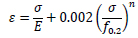
Besides, three different heat-treatments have been considered, temper T4 for EN-AW 6082, temper T5 for EN-AW 6063, and temper T6 for EN-AW 6082 and EN-AW 6061. Temper T4 is a treatment, where the material is naturally aged at room temperature, employing a combination of solution processes followed by cooling. The material is not work-hardened, leading to a material more ductile when compared to temper T6, which, conversely, is artificially heat-treated. For this reason, temper T4 leads to significant strain-hardening when compared to T6. Finally, temper T5 requires cooling after hot working and artificial ageing. According to Eurocode 9 [3], the stress-strain relation is provided in the form ε = ε(σ) according to the Ramberg-Osgood Model (R-O) (Eq. 1):
where E is Young’s modulus equal to 70 GPa, ƒ0.2 is the stress corresponding to 0.2% plastic strain, while the exponent n governs the knee of the stress-strain curve.
The exponent n of the Ramberg-Osgood Model is given by (Eq. 2):

where the stress ƒ0.1 corresponds to 0.1% plastic strain. Therefore, the ratio between the stresses ƒ0.2 and ƒ0.1 is used to characterise the “knee” of the stress-strain curve. The value of n identifies the hardening behaviour of the alloy. When the ratio ƒ0.2/ƒ0.1 tends to 1, the exponent n tends to infinity and the R-O law reduces to the elastic-perfectly plastic behaviour. Therefore, high values of the n exponent identify the low-hardening behaviour, while low values of the n exponent identify high-hardening behaviour [1, 2].
As 7000 series aluminium alloys (high strength aluminium alloys) are being fastly developed in structural engineering, it is important to underline that, even though all the investigated alloys belong to the 6000 series, the obtained empirical formulas for predicting the ultimate behaviour of aluminium alloy beam under non-uniform bending can also be applied to alloys belonging to the 7000 series. The 7000 series, introduced in Eurocode 9 as alloy EN-AW 7020, is characterized by a range of variations of the Ramberg-Osgood exponent from 18 to 23. This range is perfectly covered by the cases reported in the paper, where n varies from 8 to 55.
3. METHODOLGY
The investigation of the influence of the material properties on the non-linear behaviour of H-shaped beams under non-uniform bending moment has been carried out employing a FE model, whose accuracy has been validated against available experimental tests [19-22].
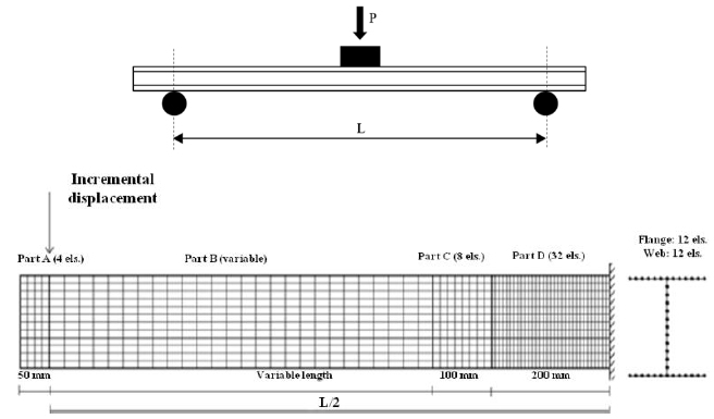
The calibration of the Finite Element Model in ABAQUS software has been carried out employing the experimental campaign developed by Moen et al. [19], where the scheme of the test set-up corresponds to the simply supported beam with a vertical load at mid-span, usually referred to as three-point bending test. The tested beam is placed on top of cylindrical supports that are free for rotation (Fig. 1) [13-17]. Because of the symmetry, only one-half of the beam is analysed. The mesh is based on the use of a 4-node shell element with reduced integration (S4R) with five integration points; it is not constant in the longitudinal direction. In particular, it is denser close to the fixed end, where the maximum bending is expected to occur. In the cantilever section, a coupling constraint applied to all the points of the section simulates a rigid diaphragm, where the displacement control is imposed to perform the numerical analyses. Finally, the influence of geometrical and mechanical imperfections on the ultimate behaviour of the I-shaped beam is accounted for by utilizing a buckling analysis to select the shape of the initial geometrical imperfections according to the first buckling mode. It is well known that the residual stresses reduce the overstrength of the metal members, and, for this reason, they should be considered in the numerical analyses. However, consideration also has to be made, observing that, in the case of aluminium alloy sections, residual stresses are small compared to steel sections [12]. Therefore, in order to simplify the finite element analyses, they are neglected.
The selected magnitude of the initial imperfections has been obtained by a scale factor of the eigenmode, which has been calibrated to obtain a maximum initial out-of-plane imperfection equal to b/500, where b is the flange width [20].
The finite element model developed has been compared with the available experimental tests, as reported in previous works by the same authors [12-15]. Besides, the finite element model was also validated by independent researchers [23-25]. However, probably because of the high computational effort needed at that time, their parametric analyses were not sufficient for setting up empirical formulas for predicting the ultimate behaviour. Therefore, the attention is, herein, focused on the non-dimensional parameters affecting the ultimate behaviour and on the corresponding non-dimensional response parameters.
In particular, the following non-dimensional parameters have been identified as those affecting the ultimate behaviour of H-shaped aluminium alloy beams subjected to local buckling under non-uniform bending:
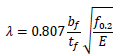
The normalised flange slenderness parameter λ is as follows (Eq. 3) [6, 7]:
• The flange-to-web slenderness ratio α is as follows (Eq. 4) [6, 7]:

• The ratio between the shear length and flange width is as follows (Eq. 5) [4-7]:

The choice of the above non-dimensional parameter has been made based on the experience acquired in the study of the ultimate behaviour of structural steel members [26-28]; also the extensive experimental evidence from stub column tests should be considered [29-32].
In particular, 10 values of λ ranging from 0.52 to 1.24 with a step size equal to 0.08 and 4 values of α ranging from 0.20 to 0.50 with a step size equal to 0.10 have been considered to cover the common range of variations of the geometry of extruded profiles. Besides, regarding the shear length, 3 values of the shear length over flange width ratio  equal to 6.25, 12.5, 18.75 have been investigated, covering both high shear and low shear actions giving rise to different loading conditions in terms of longitudinal stress gradient in the zone, where the development of the plastic hinge is expected. Finally, four values of the R-O exponent, as reported in Table 2, have been considered.
The total number of analysed cases is equal to 480, 120 for each alloy, where the material characteristics, the cross-section dimensions and the length of the tested beams change according to the ranges of variation of the parameters investigated mentioned above. Additional information can be found in a study [16] concerning low-yielding-high hardening alloys and in [17] about high-yielding-low hardening alloys.
| ALLOY | TEMPER | E [MPa] |
n | f0.2 [MPa] |
|---|---|---|---|---|
| EN-AW6082 | T4 | 70000 | 8 | 110 |
| EN-AW6063 | T5 | 70000 | 16 | 130 |
| EN-AW6082 | T6 | 70000 | 25 | 260 |
| EN-AW6061 | T6 | 70000 | 55 | 240 |
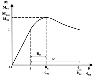
The results of the parametric analysis have been provided in terms of normalised moment-rotation curves (M / M0.2 - 0 / 00.2), which entirely describe the non-linear response of aluminium alloy beams under non-uniform bending [33]. In particular, M is the maximum bending moment along the member length, occurring at the fixed end of the analysed cantilever scheme, 0 is the rotation at the cantilever end section where the displacement is imposed and M0.2 is the elastic limit moment provided by the following equation (Eq. 6):

where We is the elastic section modulus evaluated considering a mid-thickness line-model of the cross-section, and it is equal to  . Besides, 00.2 is the rotation corresponding to the elastic limit state given by (Eq. 7):

The typical shape of a normalised moment-rotation curve is depicted in Fig. (2).
The non-dimensional ultimate flexural resistance is defined as the ratio (Eq. 8):

where Mmax is the maximum bending moment.
The parameters describing the plastic rotation capacity are reported according to the definitions proposed by Mazzolani and Piluso [33]. In particular, RO represents the stable part of the rotation capacity, which is developed before the occurrence of local buckling (Eq. 9):

while R is the total rotation capacity, including also the post-buckling behaviour (Eq. 10):

where 0m is the rotation corresponding to the maximum bending moment Mmax and 0u is the rotation occurring in the post-buckling phase when the bending moments fall below the value corresponding to the conventional elastic moment M0.2.
It is worthwhile remembering that the maximum load-bearing capacity is attained when local buckling is completely developed. This means that a kinematic mechanism is developed, locally characterised, in the section subjected to the maximum bending moment by the out-of-plane deformation of the beam flange, which is typically accompanied by the out-of-plane deformation of the web due to geometrical compatibility requirements. Therefore, yield lines are developed in the plate elements constituting the member section. The post-buckling behaviour is described by the softening branch of the moment-rotation curve, which is essentially the mechanism equilibrium curve resulting from the balance between internal work and external work, including second-order effects. During the post-buckling behaviour, the reduction of the moment resistance is accompanied by the increase of the plastic rotation, which, in turn, is due to the increase of the plastic rotation of the yield lines involved in the kinematic mechanism.
4. RESULTS AND DISCUSSION
In this section, the results obtained [16, 17] employing the parametric analyses carried out by the finite element model performed by ABAQUS [11, 34] are exploited. Aiming to predict the ultimate behaviour of H-shaped aluminium beams under non-uniform bending moment, three empirical formulas for computation, the non-dimensional ultimate flexural strength, the stable part of the rotation capacity, and the total rotation capacity, are presented. These relations were calibrated using the least-squares method to obtain the best fitting with the numerical results from the finite element simulations, as described and reported in a study [16, 17]. All these formulas provide the relation between the non-dimensional response parameters (Eqs. 8-10), the non-dimensional geometrical parameters (Eqs. 3-5) and the material properties through the parameter given by Eq. (3), including the effects of the elastic modulus E, the yield stress ƒ0.2, and the R-O exponent.
4.1. Non-dimensional Ultimate Flexural Strength
In previous works [16, 17], the authors investigated the influence of each non-dimensional parameter on the non-dimensional flexural resistance, i.e., Mmax/M0.2. In particular, analysing the results provided by FE simulations, it was immediately observed that the moment ratio Mmax/M0.2 decreases when the flange slenderness λ and between the shear length and the flange width increase, for fixed values of the flange-to-web slenderness ratio α. This paper aims to point out the role of R-O exponent n. For this reason, in Figs. (3-5), the values of non-dimensional flexural strength are reported as a function of the geometrical parameter bƒ/2tƒ for the four aluminium alloys, and for fixed values of α and . Observing the trend of curves, it is evident that for each fixed value of bƒ/2tƒ, the moment ratio Mmax/M0.2 decreases when the R-O exponent n increases; this means that, even though aluminium alloys EN-AW6082 T6 and EN-AW6061 T6 are characterized by high yielding values, the plastic overstrength capacity is limited by the high values of the R-O exponent. Conversely, the opposite behaviour occurs for low-yielding aluminium alloys EN-AW6082 T4 and EN-AW6063 T5. However, it is important to underline that the moment ratio Mmax/M0.2 is a measure of the flexural overstrength of the member, i.e., the capacity of the aluminium H-shaped beam exhibiting a hardening behaviour and, as a result, a plastic overstrength.
Moreover, it is possible to observe that the mathematical structure of the trend line is a power function. For all these reasons, an empirical regression is proposed to compute the maximum non-dimensional flexural resistance as a function of the flange slenderness λ, the flange-to-web slenderness ratio α, the ratio between the shear length and flange width and the R-O exponent n. By using the least square method, the following expression has been obtained from the best-fitting of the finite element simulation results (Eq. 11):
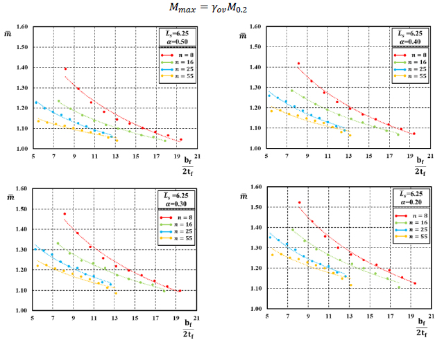
 for α=0.50,0.40,0.30 and 0.20 and = 6.25.
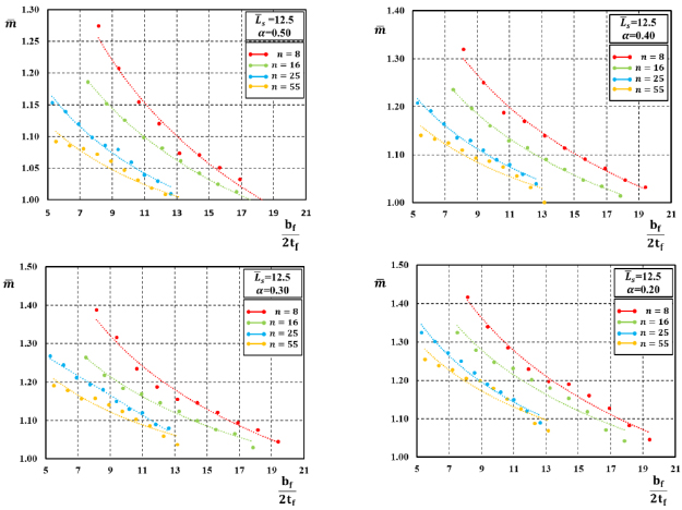 for α=0.50,0.40,0.30 and 0.20 and = 12.5.
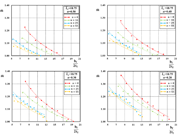 for α=0.50,0.40,0.30 and 0.20 and = 18.75.

where the values of the regression coefficients Ci are reported in Table 3.
, R and R0.| - | C1 | C2 | C3 | C4 | C5 | C6 | C7 | C8 |
|---|---|---|---|---|---|---|---|---|
|
0.001 | -0.377 | 1.498 | -0.015 | 0.0002 | -0.068 | 0.084 | -0.472 |
| R0 | 82.831 | -0.166 | 1.942 | -0.287 | 1.789 | 0.166 | 0.254 | - |
| R | 222129.692 | -0.891 | -1.645 | -0.775 | -0.004 | -0.0005 | 4.560 | - |
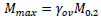
Fig. (6) provides a comparison between the values obtained through FE simulations and the corresponding predictions derived from Eq. (11). The accuracy of the regression is very high as testified by the average value of the ratio between the value predicted by Eq. (11) and the FE result, equal to 1.0001 with a standard deviation, of the same ratio, equal to 0.0151. Besides, the model factor γFE according to prEN 1993-1-14:2020 [11] has been computed, and it is equal to 1.0250, corresponding to the 5% fractile. Such a low value confirms the high accuracy of the best fitting (Eq. 11). By denoting the non-dimensional flexural resistance as , given by the empirical relation Eq. (11), with γov underlining the meaning of overstrength factor assumed by this ratio, it is possible to estimate the maximum bending moment of H-shaped aluminium beams subjected to non-uniform bending through Eq. (12):
4.2. Rotation capacity of H-shaped aluminium beams
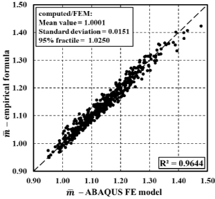
A similar approach has been followed for the development of empirical relations to be used for predicting the total value of the rotation capacity R and its stable part R0. In particular, by analyzing the results of FE simulations, as reported in studies [16, 17], it can be observed (Figs. 7-12) that the rotation supply of H-shaped aluminium beams under moment gradient reduces for increasing values of the normalised flange slenderness and also for increasing values of the non-dimensional shear length.
Besides, the I-section ductility increases when the flange-to-web slenderness α increases. Moreover, the influence of the variation of the R-O exponent on the ductility of H-shaped beams can also be observed.
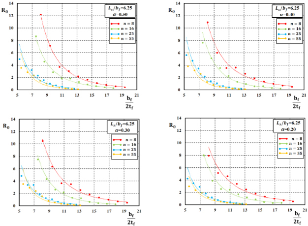
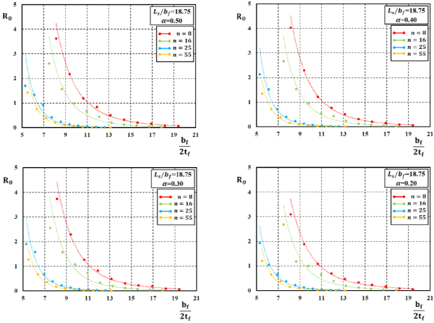
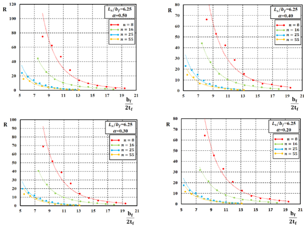
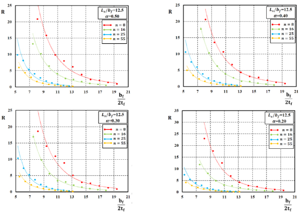
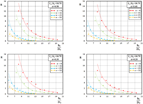
In particular, Figs. (7-12) show the trend between the rotation capacity, either the stable part R0 or the total value R, and the geometrical flange slenderness parameter bƒ/2tƒ for fixed values of and α. For a fixed value of the bƒ/2tƒ ratio, the rotation capacity decreases when the value of the R-O exponent n increases.
Starting from the results obtained by FE simulations and considering the above-reported observations, the equations for the best-fitting prediction of the rotation capacity of H-shaped aluminium alloys have been derived according to the following relations (Eqs. 13 and 14):
a) Stable part of the rotation capacity:

b) Total rotation capacity:

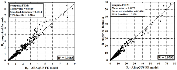
Table 3 provides the regression coefficients also for Eqs. (13 and 14). Moreover, the accuracy of the proposed regressions is reported in Fig. (13), reporting the comparisons concerning the stable part and the total rotation capacity on the left and right, respectively.
In particular, the average value of the ratio between the value of R0 predicted by Eq. (13), and the value resulting from FE simulations is equal to 0.9516, with a standard deviation equal to 0.1614. Besides the linear correlation coefficient R2 is equal to 0.9683, while the model factor γFE computed according to prEN 1993-1-14:2020 [11] is equal to 1.2166.
Regarding R, the ratio between the value computed using Eq. (14) and the value resulting from the ABAQUS finite element model has an average value equal to 0.9675 with a standard deviation equal to 0.1496. The model factor γFE according to prEN 1993-1-14:2020 [36], is equal to 1.2128, while R2 is equal to 0.9793.
Therefore, to predict the rotation capacity of H-shaped aluminium alloys under non-uniform bending, the authors propose the use of Eqs. (13 and 14) with the respective values of the model factors (safety factors) γFE computed according to prEN 1993-1-14:2020 [11].
As soon as the value of R0 and R are computed by Eqs. (13) and (14), the knowledge of the value of the rotation corresponding to the elastic limit state 00.2, allows to immediately predict the ultimate rotation 0u and the rotation at the maximum bending moment 0m through the Eqs. (9 and 10), respectively. Moreover, it has been checked that the ultimate rotation of the beam corresponding to the ultimate true strain of the material is achieved for values of the rotation 0u higher than those occurring when the ratio M/M0.2 falls below 1.0.
CONCLUSION
In this paper, the influence of the Ramberg-Osgood exponent on the ultimate behaviour of H-shaped aluminium beams under non-uniform bending has been investigated. In particular, four alloys belonging to the 6000 series and characterized by different heat-treatments have been analysed. The attention has been focused on the prediction of the non-dimensional ultimate flexural resistance and rotation capacity using empirical formulas derived from the outcome of finite element simulations.
The results of a wide parametric analysis based on 480 finite element simulations have been briefly presented to grasp the influence of non-dimensional parameters, as the flange slenderness λ, the flange-to-web slenderness ratio α and the ratio between shear length and flange width, on the ultimate behaviour of H-shaped aluminium alloys. The analyses have been extended to the influence of the Ramberg-Osgood exponent n.
In particular, it was possible to observe that for increasing values of n the non-dimensional flexural strength and the plastic rotation capacity, both in terms of R and R0, tend to decrease. This means that, after the development of yielding, low yielding-high hardening aluminium alloys (EN-AW6082 T4, EN-AW6063 T5) exhibit better plastic redistribution and rotation capacity than high yielding-low hardening aluminium alloys (EN-AW6082 T6, EN-AW6061 T6).
Besides, starting from the results obtained by FE simulations, empirical relations for estimating the non-dimensional ultimate flexural resistance , the stable part of rotation capacity R0 and the total rotation capacity R have been derived using the least-squares method. The comparison between the results obtained by ABAQUS’s analyses and those provided by the empirical relations shows excellent accuracy in the case of . This accuracy reduces when the aim is the prediction of the rotation capacity, but it remains still satisfactory and is controlled by an appropriate evaluation of the model factors, as suggested in prEN1993-1-14.
The need for the relationship to estimate the ultimate rotation and maximum plastic moment belongs to the idea of using such kinds of alloys in seismic situations and, in this regard, significant work has been promoted by the European Community to include aluminium alloy structures in the new draft of the Eurocode 8. It is well known that, under seismic forces, structural members constituting the dissipative zones have to exploit their dissipative capacity; therefore, from the design point of view, namely to apply hierarchy criteria, the knowledge of the members overstrength capacity is of huge importance. From the assessment point of view, the estimation of the ultimate rotation of the members allows evaluating the actual dissipative capacity of the members. It is important to underline that such formulas are based on monotonic numerical simulation, while a more exhaustive evaluation of the actual ultimate rotation can be done through cyclic tests. This issue is the subject of forthcoming works.
It is worthwhile underlining that, even though the formulas suggested by the authors could seem quite complex, it has to be considered that they can be easily applied by employing a spreadsheet that is within the reach and availability of any designer. Unfortunately, the formulas cannot be simplified because they cover not only one material but a wide family of materials, the aluminium alloys, which are characterized by a wide variation of the hardening behaviour through the values assumed by the Ramberg-Osgood exponent.
Besides, it has to be considered that the complexity of the suggested formulas is comparable to that of the formulas given in EN1998-3 [11] when dealing with the same problem regarding reinforced concrete structural elements. Indeed, the suggested formulas are probably simpler than those given in EN1998-3 and surely more accurate.
The results herein presented are suitable for a quick evaluation of the ultimate performances of aluminium beams under moment gradient, as required for standardization purposes, so that they can be introduced in the informative annexe L of EN 1999-1-1, within the activities of the project team encharged of the revision on Eurocode 9.
Finally, it is worthwhile stressing that empirical formulas derived from any parametric analysis can be applied to cases different from those investigated, provided that the governing parameters are within the range of variation investigated by such a parametric analysis. Therefore, readers should be aware that any extrapolation of the obtained formulas outside of the investigated ranges (λ ranging from 0.52 to 1.24, α from 0.20 to 0.50, from 6.25 to 18.75 and n from 8 to 55) of the governing non-dimensional parameters can lead to inaccurate results.
CONSENT FOR PUBLICATION
Not applicable.
AVAILABILITY OF DATA AND MATERIALS
Not applicable.
FUNDING
None.
CONFLICT OF INTEREST
The authors declare no conflict of interest, financial or otherwise.
ACKNOWLEDGEMENTS
Declared none.

