All published articles of this journal are available on ScienceDirect.
Structural Performance of Straw Block Assemblies under Compression Load
Abstract
Background:
In recent decades, the enduring interest and continued development of straw bale as a walling material are based on its beneficial properties. Straw bale is a biomaterial that contributes greatly to carbon footprint reduction and offers excellent thermal insulation. It is proved that plastered straw bale assemblies have good mechanical properties and can be used for the construction of a single storey building. It is known that straw bale presents high displacement in the assemblies; thus, pre-compression is a major step that helps to push down straw bale so as to avoid future structural failure in the wall. There is no clue yet if this method is structurally beneficial than to stabilized single straw bales before assembling them into a structural panel.
Objective:
This paper presents the structural performance of straw block assemblies under compression loads.
Method:
Straw blocks and mortar were used to construct plastered and un-plastered wall panels, which were tested under uniformly distributed compression load till failure.
Results:
The results obtained show that plastered straw block assemblies can support at least 286 KN/m2, which is higher than the minimum slab load 18.25KN/m2, including imposed load for a residential house. In addition, the strength of plastered straw block assemblies plastered with cement-gum mortar, 0.3 N/ mm2 is greater than the strength of a single storey building (0.19N/mm2). Furthermore, results indicate that un-plastered and plastered straw block assemblies perform better than un-plastered and plastered straw bale assemblies. Plastered straw block assemblies support up to 52KN while plastered straw bale assemblies support only 41.1KN.
Conclusion:
Under compression load, straw block assemblies have a load carrying capacity greater than the minimum slab load. Therefore, Straw block can be used for the construction of a single storey building.
1. INTRODUCTION
Masonry is a well-proven building material possessing excellent properties in terms of appearance and durability [1]. Masonry was exploited to construct the most significant, magnificent, and long-lasting structures on Earth [2]. Constituent elements of masonry have progressed through several stages of development, depending on the evolution of technology and the needs of the population. The earliest forms of masonry were mud and straw hand-moulded bricks [3]. Fired clay brick became the principal building material in the United States during the middle 1800s, while concrete masonry was introduced to construction during the early 1900s and, along with clay masonry, are used for all types of structures to date [4]. Straw bale masonry was introduced in Nebraska, North America, in the 19th century [5-7]. Since then, there have been an increasing number of projects using straw bale around the world, such that in September 2017, the number of registered straw bale houses was 1672 [8]. Straw bale construction has now become more recognized globally and has developed into a contemporary building typology [7].
The first masonry structures were unreinforced and were intended to support mainly gravity loads. In the last 45 years, the introduction of engineered reinforced masonry has resulted in structures that are stronger and more stable to support lateral loads, such as wind and seismic [4]. With the recent climate change, energy, and high temperatures, the interest in using straw bale as a construction material has increased worldwide. This result from the need for developing building envelopes that are climate responsive and can significantly reduce building’s energy consumption. The enduring interest and continued development of straw bale construction are based on its beneficial properties: Straw is a renewable, inexpensive, and readily available resource for sustainable construction [9]. Straw bale provides a significant benefit in terms of cost and human health [10]. Moreover, the thermal property of straw bale is around 0.06W/mK, which offers excellent thermal insulation [11]. For 450 to 500 mm thick walls, the thermal transmittance (U-values) is about 0.13 to 0.19 W/m2 K, depending on bale density and thermal conductivity [9]. According to Bartels [12], straw bale construction is aligned with the energy goals because of its low operating (good thermal performance) and low embodied energy (minimally processed, locally or regionally and widely available). Straw bale construction techniques will assist society in coping with extreme weather while in low-income households, less disposable income would be expended on power bills [13]. Nails [14] mentioned that other than straw bales’ sustainability benefit, around 10 000 euros could be saved on the cost of construction of a normal three-bedroom house whereas, up to 75% on heating/ cooling cost would be saved if straw bale is used as a construction material. Straw bale is a low-cost material; the price of constructing a straw building is about 1200 €/m2 lesser than that of a standard building, which is about 1500 €/m2 in Northern Italy [15]. It is also a natural, non-toxic, and biodegradable material, and therefore, is regarded as sustainable green material [16, 17].
Depending on the type of constituent’s elements, masonry strength varies from one type of structure to another. The mechanical properties of concrete block or brick masonry differ from that of straw bale masonry. However, all types of masonry should support at least the expected loads for its intended life. In load-bearing masonry, resistance to compressive stress is the predominant factor in design [1]. Hence an accurate determination of compressive strength is extremely important [18].
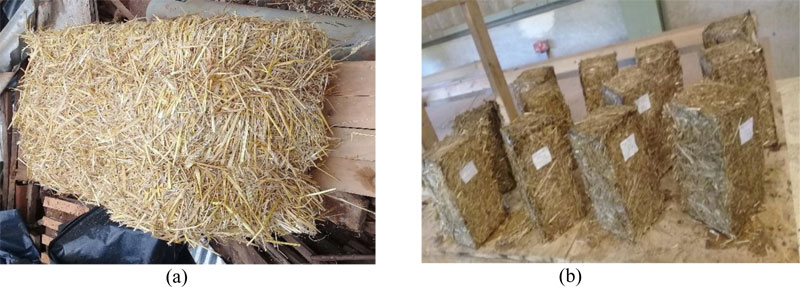
Although straw bale has a low compressive strength, around 0.017N/mm2 [19, 20], load-bearing plastered straw bale forms a composite structure that works like a sandwich panel. Straw bales and plaster work together to create a composite structural system similar in concept and performance to a structural insulated panel [21]. The relationship between plaster and straw bale is the same as in the web to flange in a steel I-beam [22]. Plastered straw bale assemblies gain their strength and stiffness from the render coats [23, 24]. Historically, the oldest building made of the straw bale is over 100 years old [14,25]. Structures in Nebraska and Alabama have demonstrated their durability in a climate with variable moisture and temperature [26]. Up till now, straw bale construction consists of stacking straw bale in a running bond and use of different techniques to push down straw bale wall before plastering them. It is not mentioned in previous works, whether this method of straw bale construction is structurally beneficial than that proposed herein. This study consists of using stabilized straw blocks instead of straw bale in masonry. As presented in Fig. (1), straw bale is made of straw stems tied down with two or three strings while straw block (Fig. 2) is made of chopped straw stems mixed with natural binder (gum arabic) to form a solid material. The length of chopped Straw stems was in the range of 1 to 8 cm. Njike et al. [20] provided a clear description of straw blocks manufacturing processes. The average density (522Kg/m3) of the manufactured straw blocks is four times greater than the minimum density of straw bale (120Kg/m3) required as per the Appendix S of International Residential Code [27]. This appendix regulates load bearing straw bale structure. The aim of this study is to show that straw block assemblies perform better in load bearing masonry than straw bale assemblies.
2. MATERIALS AND METHODS
The quality of masonry depends on its constituent elements. These elements are soil block, concrete, stone, or straw bale and mortar. In this study, wheat straw block and mortar were used to construct load-bearing masonry. Straw blocks were made of a mixture of chopped straw, gum Arabic, and water. Gum Arabic is a natural gum from the hardened sap of acacia trees. Gum Arabic was crushed and passed through a sieve size of 1.2mm. A chemical test was conducted on gum Arabic using BRUKER S1TITAN 600 and the result shows that Gum arabic contains 43% of CaO, 2% of Al2O3, 27% of MgO, and 26% of K2O. Straw blocks have the same dimension as the normal stabilized soil block used in Kenya. As mentioned previously, Njike et al. [20] provided a clear description of straw block manufacturing processes. The characteristics of the wheat straw block are shown in Table 1. Cement-gum Arabic based mortar was used. Gum Arabic was added to the mortar to provide good bonding between blocks and mortar. In fact, the type of mortar used in construction depends on the characteristic of the blocks. River sand from a local supplier in Kenya was used and the particle size distribution is presented in Fig. (2). Nguvu cement of resistance 32.5 MPa was used in this study. Nguvu cement is a locally manufactured pozzolanic cement with a wide range of applications in construction. Three types of mortar were used: Cement-sand mortar of proportion 1:4, partial replacement of cement with 50% of gum Arabic, and 25% gum Arabic. The compressive strength of mortar cubes of 100 mm was cast and tested on a UTM machine at 28 days while the strength of the block was determined using AMSLER’S compression testing apparatus. The characteristics of straw block and plaster are presented in Table 2 and Table 1, respectively.
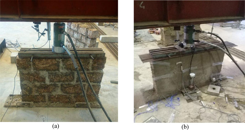
Manufactured straw bocks and mortar were used to construct plastered and un-plastered wall panels. The plastering was done after 3 days for plastered panels and the panels were cured and tested at 28 days. For each type of mortar, two wall panels were constructed and tested under uniformly distributed compressive load. The dimension of panels were 920 mm (length) x 635 mm (height) x 140 mm (thickness) mm for un-plastered panels and 920 mm (length) x 635 mm (height) x 150 mm (thickness) for plastered panels. The external applied concentrated load was uniformly distributed to the wall panel through the still beam placed at the top of the wall. The load setup was as shown in Fig. (3). Applied load was measured by a load cell type CLP-50B (capacity 50tf and sensitivity 2mV/V). In addition, transducers were used to measure displacement in the panel. Depending on the availability of transducers, transducer type DT-100A (capacity 100mm and 1.5mV/V) was used for un-plastered panel while transducers of type DDP-30AS2, of capacity 30mm, were used on plastered panel. For plastered wall panels, strain gauges type PL60-11-3L of sensitivity 2.08 were used to measure strain at different points on the wall (Fig. 3-b). The load was manually applied by incremental loading with a hydraulic loading jack of capacity 14.5kg. Applied load was printed out every 5 seconds on the data logger and the compressive strength of the wall panel was calculated as the ratio of applied load to the surface.

| Type of block | Length (mm) | Width (mm) | Thickness (mm) | Weight (Kg) | Compressive strength (N/mm2) |
|---|---|---|---|---|---|
| Wheat Straw Block | 290 | 140 | 140 | 3.08 | 1.25 |
| Type of mortar | Constituent elements | Proportion per volume | Compressive strength (N/mm2) |
|---|---|---|---|
| Type 1 | Sand: cement | 1:4 | 3.1 |
| Type 2 | Sand: cement: gum arabic | 1:0.75:0.25 | 2.4 |
| Type 3 | Sand: cement: gum arabic | 1: 0.5: 0.5 | 1.8 |
3. RESULTS AND DISCUSSIONS
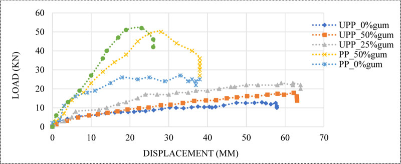
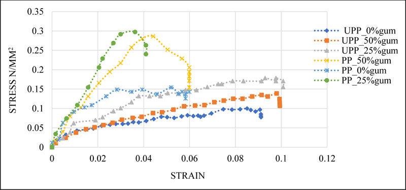
The average value of compressive strength, load carrying capacity, and displacement in the different types of wall panels are presented in Table 3. Fig. (4) shows the load displacement curves, while the behavior of the wall panels is shown in Fig. (5).
| Type of wall | Average Load carrying capacity (kN) | Average load carrying capacity (kN/m2) | Average Displacement in the panel (mm) | Average Compressive Strength of panel (N/mm2) |
|---|---|---|---|---|
| Un-Plastered Panel with 0% gum (UPP_0%gum) | 13 | 100.93 | 47 | 0.1 |
| Un-Plastered Panel with 25% gum (UPP_25%gum) | 22 | 170.81 | 62 | 0.18 |
| Un-Plastered Panel with 50% gum (UPP_50%gum) | 18 | 102.97 | 62 | 0.14 |
| Plastered Panel with 0% gum (PP_0%gum) | 27 | 139.75 | 18 | 0.15 |
| Plastered Panel with 25% gum(PP_25%gum) | 52 | 297.48 | 18 | 0.3 |
| Plastered Panel with 50% gum (PP_50%gum) | 50 | 286.04 | 28 | 0.28 |
3.1. Maximum Stress Capacity of Straw Block Assemblies
The average value of compressive strength, load carrying capacity, and displacement in the different types of wall panels are presented in Table 3. The strength of plastered straw block assemblies were 0.3, 0.28, and 0.15 N/mm, respectively, for the different types of plaster. As shown in Fig. (5), the strength of panels plastered with type 1 mortar is smaller than those plastered with type 2 and type 3 mortar. The addition of gum Arabic in plaster increased the resistance of plastered and un-plastered assemblies. But wall panels plastered with type 2 mortar have the best value compared to other panels. As stated earlier, a masonry wall should support at least the expected loads. The basic aim of structural design is to ensure that a structure fulfills its intended function throughout its lifetime without excessive deflection, cracking, or collapse [1]. Generally, a load-bearing masonry structure is intended to carry a slab or a roof. For residential houses, the minimum slab load and imposed load is about 18.25KN/m2 (Table 4). This load is smaller than the load-carrying capacity of plastered straw block assemblies, which is 297.48 KN/m2 and 286.04 KN/m2, respectively, for assemblies plastered with type 2 and type 3 mortar. Appendix R of International Residential Code [28] stipulates that the allowable vertical load (life and dead load) on top of load-bearing straw bale walls shall not exceed 360 pounds per square foot (17.24 kN/m2). This maximum load for straw bale assemblies is 17 times smaller than the load-carrying capacity of straw block assemblies. In addition, the design load of a single storey building is 0.19N/mm2, which is smaller than the strength of plastered straw block assemblies; 0.3 and 0.28 N/mm2, respectively, for panels plastered with mortar types 2 and 3. Thus, straw block can be used for the construction of at least a single storey house. Fig. (4) shows that panels plastered with type 1 mortar failed under a load less than 30KN while the other panels plastered with mortar types 2 and 3 continued to resist more load up to 50 KN. The displacement in plastered straw block assemblies is 18 mm, about 3 times smaller than the displacement (62mm) in un-plastered panels. The displacement reduces considerably when the panels are plastered (Fig. 4). Walker [29] reported that at maximum load, the settlement in straw bale pre-compressed panel is 120 mm, while in normal construction panel (panels not pre-compressed), the settlement is 220 mm. Hence, displacement in un-plastered straw block assemblies is 2 times smaller than the displacement in a pre-compressed straw bale assemblies. Therefore, even pre-compressed, straw bale assemblies have high displacement than straw block assemblies. Walker [29] also reported displacement of 55 mm in lime plastered panels, while Vardy [24] reported displacement of about 20 mm in cement-lime plastered panels. From these data, it can be deduced that plastered straw block assemblies structurally perform better than straw bale assemblies.
3.2. Failure Pattern
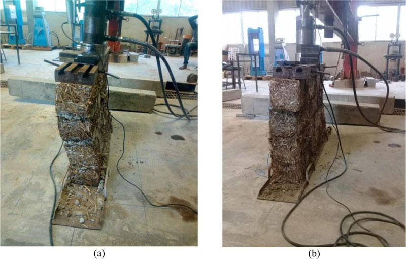
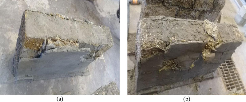
The failure patterns of the plastered and un-plastered straw block assemblies are respectively shown in Figs. (6) and (7). It was observed that cracks appeared along the mortar bed joint (lines of weakness) of the un-plastered panel in which cement mortar was used; these cracks show the separation of a straw block from mortar joint (Fig. 6-a). The peeling off of plaster was also observed on the cement plastered straw block panels (Fig. 7-a). Furthermore, no cracks appeared on an un-plastered panel made with mortar types 2 and 3. It is observed in Fig. (6-b) that the panels appeared normal at maximum load. Mortar that included gum arabic bonded well on the straw block compared to cement mortar. Therefore, partial replacement of cement by 25% and 25% of gum arabic have greatly influenced the bonding strength of straw block assemblies. However, Table 2 shows that the strength of the mortar cube that included gum arabic was smaller compared to that of cement mortar. The behavior of straw block assemblies is dictated by the interface between mortar and straw block. According to Mosalam et al. [2], the interface is the weak link in masonry and it dominates the behavior of masonry assemblage while bonding strength increases the structural integrity of masonry [4]. Whence it follows that a good bond between block and mortar is preferable to high strength mortar [32]. The incorporation of gum Arabic in the mortar has reduced the compressive strength of mortar but has increased the bonding strength between the straw block and mortar. This shows that the strength of masonry to withstand compression load depends on the type of mortar and the bonding strength between the block and mortar joint.
3.3. Advantages of Straw Block on Straw Bale
The technique of straw block construction is similar to that of conventional material; thus it does not require additional training from builders as straw bale does. In addition, it does not require further pre-compression like in straw bale construction techniques. The use of joint mortar in straw block assemblies increases structural integrity [4], which is not the case in straw bale assemblies where the mortar joint is not used. Furthermore, the strength of straw block assemblies is far better than that of straw bale assemblies. Only a few data is published on the strength of the plastered straw bale panel. Walker [29] reported that the maximum load for pre-compressed and lime rendered straw bale assemblies was respectively 19.1KN and 41.1KN. On the other hand, Vardy [24] reported that the maximum load for cement-lime plastered straw bale assemblies was 22KN. From this study, the maximum load of straw blocks assemblies was found to be 22 KN and 52 KN, respectively, for un-plastered and plastered panels made of mortar type 2. Un-plastered and plastered straw block assemblies support more load than plastered and un-plastered straw bale panels. Thus, Straw block assemblies structurally performed better than straw bale assemblies.
CONCLUSION
The results obtained show that plastered straw block assemblies can support at least 286 KN/m2, which is higher than the minimum slab load 18.25KN/m2, including imposed load for a residential house. In addition, the strength of plastered straw block assemblies (0.3N/mm2) plastered with cement-gum mortar is greater than the strength of a single storey building (0.19N/mm2). Therefore, Straw block can be used for the construction of a single storey building. Furthermore, results obtained show that un-plastered and plastered straw block assemblies perform better than un-plastered and plastered straw bale assemblies. Plastered straw block assemblies support up to 52KN while plastered straw bale assemblies support only 41.1KN. From a durability point of view, in the construction of any type, engineers or practitioners should follow the established good practice guideline for masonry. Straw bale is a natural material and its durability will be influenced by the presence of water. Therefore, good practices (roof overhangs, increasing the height of slab beam from the floor, using moisture barrier at the bottom course straw bale) will help in minimizing problems such as moisture in straw block masonry.
AUTHOR CONTRIBUTIONS
Conceptualization, M.N., W.O.O. and S.O.A. ; methodology, M.N. and W.O.O.; formal analysis, M.N., W.O.O. and S.O.A.; data curation, M.N.; writing—original draft preparation, M.N.; writing—review and editing, M.N., W.O.O. and S.O.A.; visualization, M.N.; supervision, W.O.O. and S.O.A.; funding acquisition, M.N.; W.O.O. and S.O.A.; All authors have read and agreed to the published version of the manuscript.
CONSENT FOR PUBLICATION
Not applicable.
AVAILABILITY OF DATA AND MATERIALS
Not applicable.
FUNDING
This research was funded by the African Union Commission (AUC) as a contribution to high education in Africa through the Pan African University.
CONFLICT OF INTEREST
The authors declare no conflict of interest, financial or otherwise.
ACKNOWLEDGEMENTS
The first author wants to appreciate the African Union Commission and the Pan African University for making funds available for this study.

