All published articles of this journal are available on ScienceDirect.
An Enhanced Beam Model for the Analysis of Masonry Walls
Abstract
Background:
Some typologies of masonry constructions (e.g. towers or walls with openings) can be reasonably studied through simple beam or frame-like models. For these structures, shear mechanisms often play an important role inducing failure and collapse.
Objective:
The paper presents an enriched beam model for studying the in-plane response of masonry walls. Initially formulated for masonry columns, towers and masonry slender structures in general, the model is now modified in order to also capture the shear failure mechanisms, in addition to the flexural ones.
Methods:
Starting with a one-dimensional no-tension model, a strength domain in the plane of the axial and tangential stress of the beam has been added, which has been defined by limiting both the stress shear component with respect to any possible direction and the main compressive stress.
Results:
The model, implemented in the FEM computational code MADY, allows for short computational times in studying the response of single panels as well as walls with openings.
Conclusion:
Comparisons of some experimental results from literature and some numerical results from more refined 2D models show the effectiveness and accuracy of the model’s predictions in terms of global and local response.
1. INTRODUCTION
The issue of modelling masonry structures is still an open one in structural engineering. This is due to the complexity of the material’s mechanical behaviour together with the great variety of structural types and constituents, that is mortar and bricks, and their textures. Meanwhile, seismic assessment, repair and strengthening of ancient masonry buildings is a priority, as such structures represent a large part of the cultural heritage of the Mediterranean basin. In particular, masonry’s lateral load capacity is crucial in seismic areas, where old masonry buildings have often exhibited high vulnerability to earthquakes.
Within this framework, nonlinear static procedures and equivalent-frame models have become very popular and attractive for practical engineering applications. The increasingly relevant role played by nonlinear static analyses in recent decades, and the widespread use of equivalent-frame models for studying ordinary masonry buildings stem from a common reason: the advantage of accounting for nonlinear structural behaviour, while preserving relative simplicity and modest computational costs.
Substantially, in the equivalent-frame approach, a masonry wall with rather regularly spaced openings can be idealized as composed of a series of panels - distinguished into piers and spandrels - connected by rigid nodes, whose dimensions can be defined through the alignments of the openings and/or the “effective” heights of the piers revealed by the damage patterns occurring under earthquakes and codified by the relevant literature [1, 2]. A thorough discussion concerning the features and benefits of using such models in comparison with others can be found in a few studies [3-5].
A large number of models following the equivalent-frame method have been proposed in the literature over the last decade [6-10]. Most of these make use of macro-elements to represent piers and spandrels. Often, they are developed assuming the classical hypotheses of a beam and make use of a limited number of nodes. Furthermore, they generally rely on a phenomenological description of the constitutive behavior of the panel, especially for shear resistance behavior. The Interested readers may refer to another study [11] for a comprehensive state-of-the-art review.
This paper presents an advanced one-dimensional continuum model for non-linear static analysis of masonry shear walls.
In the previous research by the authors, a numerical model was defined, which performed non-linear static and dynamic analyses on masonry columns, arches, towers, and slender structures in general. The model relies on a costitutive equation formulated in terms of generalized strain and stress for beams with various cross-sections, under the hypotheses that the material is non-linear elastic, unable to withstand tension with limited compressive strength [12, 14]. Furthermore, to describe the cyclical behavior and seismic response of masonry elements more realistically, a damage process under compression has been introduced [15]. The model has been implemented in the FEM computational code MADY and applied to the study of several slender masonry structures, which typically exhibit flexural behavior and consequent failure mechanism [16, 17].
Indeed, in the past one-dimensional no-tension models have been used extensively to study problems of the stability of masonry columns [18-20], the static and dynamic response of unreinforced and reinforced arches and vaults [21-23], as well as the out-of-plane behavior of masonry panels and walls. The same does not hold for the study of the in-plane behavior of masonry panels under lateral actions. In this case, as is widely known, panels are likely to undergo various distinct failure mechanisms, or a combination of some of them: for flexural behaviour (rocking/toe-crushing failure), as well as for shear with diagonal cracking or sliding along bed-joints [3, 24], which cannot be modelled using classical no-tension beam models.
The proposed constitutive model has been enhanced to address shear behaviour and account for failure with diagonal cracking in masonry panels. To this aim, the beam is formulated according to the Timoshenko theory to account for shear deformations; then, a constitutive law is defined for the shear force, in addition to that proposed for the axial one and bending moment.
Essentially, the constitutive model is characterized by a strength domain in the plane of the axial and tangential stresses of the beam, which has been defined by limiting the stress shear component with respect to any possible plane of the panel; namely, not only with respect to the one orthogonal to the beam axis. Furthermore, in analogy to the proposal for the shear stress, the principal compressive stress, rather than the axial stress component of the beam, has been limited to achieving maximum strength.
In the following, the proposed model is first presented, and then some numerical results are provided and compared to some experimental data available in the literature.
Then, some numerical analyses are conducted in order to highlight the potential of the model to approximate the 2D solution. To this end, some results obtained through the proposed models are compared with those obtained via the commercial code ANSYS [25] and via the formulated bi-dimensional masonry-like model [26].
Lasly, preliminary results on an idealized wall with a centered opening are provided as an example for practical applications.
2. MODEL SPECIFICATIONS
In order to introduce a constitutive equation also for shear behaviour, in addition to axial/flexural one, shear deformations are accounted for according to the Timoshenko theory (see Section 2.1).
Then, a nonlinear-elastic constitutive model is assumed for describing masonry’s response. Specifically, a strength domain in the plane of the stress components of a 2D beam (σz-τzy) has been defined, as explained in detail in Section 6.
Given the kinematic constrains and the material constitutive laws, the patterns of the axial stress σz and the tangential stress τzy over the beam’s cross-section can thus be determined for any strain pattern, as shown by the examples provided in Section 8. Finally, by simply integrating these stresses, a constitutive relation which associates the generalized stresses axial force N, shear V and bending moment M- to the generalized strains - ε, κ and γ- has been obtained.
2.1. Kinematic Hypothesis
According to the Timoshenko beam theory, cross-sections remain plane after bending but not necessarily normal to the deformed axis of the beam. Hence, the displacement field is identified through the longitudinal and transverse displacements of the beam’s axis, u, υ and the rotation of the cross-section φ, which is independent of υ.
The total slope of the deflected beam’s axis is due to both bending and shear, and is given by:
 |
(1) |
where z denotes the abscissa along the beam axis and γ is the transverse shear strain. Overall, the generalized strains are given by:
 |
(2) |
where ε is the extensional strain and κ the curvature of the beam axis.
Lastly, it is worth noting that, in view of the hypothesis of plane sections, each longitudinal fiber undergoes the axial strain:
 |
(3) |
where y is the distance between the fiber and the geometrical centre of the cross-section.
2.2. Constitutive Models and Definition of the Strength Domain σz-τzy
With reference to the coordinate system shown in Fig. (1), let’s assume that the stress state at any point of any beam’s cross section is completely described by the components σz (axial stress) and τzy (tangential stress). The formulation of the model stems from the idea of defining a strength domain σz-τzy while keeping in mind a plane state of stress, where σy is supposed to be nil (σy = 0).
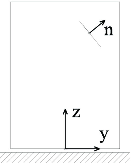
In particular, the beam’s strength domain σz-τzy has been defined by requiring some conditions on the stress to be satisfied. As widely used in the framework of no-tension beam models [27], the material does not withstand traction in the z-direction, i.e. σz is assumed to be non-positive. Moreover, with reference to a plane state of stress, the new condition assumed herein -referred to in the following as Condition (1)- requires that, at any point of the panel, the shear stress component τn on any plane - defined by its normal direction n (Fig. 1)- must respect the Mohr-Coulomb criterion, that is:
 |
(4) |
where σn denotes the normal stress component parallel to n, and τo > 0 and m < 0 are two constant material parameters, usually known as cohesion and internal friction, respectively.
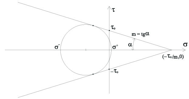
With reference to the plane (σ, τ), the foregoing condition corresponds to requiring that any state of stress in the panel, which can be represented graphically through the Mohr circle, will be admissible if it is internal to the cone with vertex at point (-τo /m,0) and identified by the half-lines τ = ±(τo +mσ). Hence, by requiring that the circle be tangent to these two half-lines (Fig. 2), it is a simple matter to verify that Eq. (4) can also be written as
 |
(5) |
where σ- and σ+ denote the principal stresses.
The second condition i.e. Condition (2) consists of assuming that the minimum negative normal stress (compression) on any plane is greater than the minimum admissible compressive stress τ0, namely
 |
(6) |
Referring to the reference system (o,y,z) depicted in Fig. (1), where the z-direction corresponds to the beam’s longitudinal axis, let’s assume that the plane stress state in the panel is
 |
(7) |
where σy is assumed to be negligible (quite an acceptable hypothesis especially for modest stress states [3]).
Consequently, the principal stresses turn out to be
 
|
(8) |
and the domains D1 and D2 that respectively guarantee fulfillment of Conditions (1) and (2) can be defined in the plane (σz, τzy).
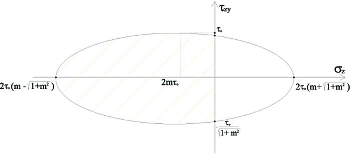
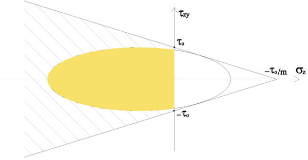
Specifically, by substituting Eq. (8) into Eq. (5), the domain D1 shown in Fig. (3) has been obtained. Its boundary is the ellipse defined by the equation
 |
(9) |
with center at point (2mτzy, 0) and half minor and major axis respectively equal to τo and  (Fig. 3). The ellipse intersects the reference σz-axis at the points
 |
(10) |
and the τzy-axis at the points
 |
(11) |
As per the condition given on σz (i.e. σz≤0), the domain of interest is limited to the portion in the half-plane of the negative σz (hatched area in Fig. 3).
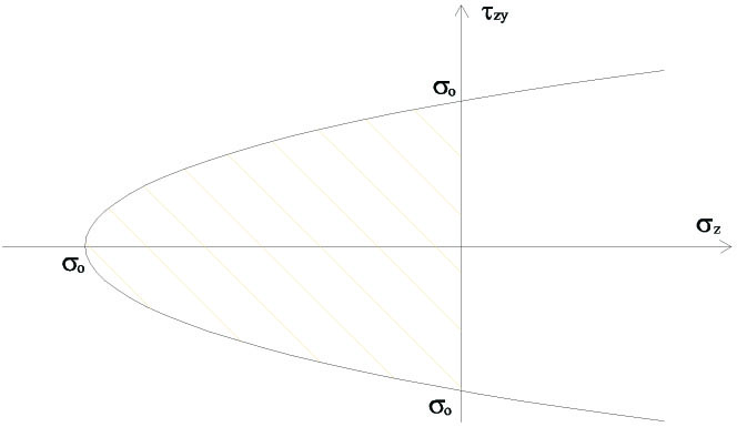
Referring to Condition (2), domain D2 is defined by substituting Eq. (8) into Eq. (6), (Fig. 4). It is limited by the parabola with equation
 |
(12) |
with axis of symmetry coincident with the σz-axis, vertex at point (σo,0) and intersecting the τzy-axis at points (0,±σo). Also in this case the domain is limited to the portion belonging to the half-plane of negative σz (Fig. 4).
Obviously, simultaneous fulfillment of both Conditions (1) and (2) is guaranteed if the components of stress (σz, τzy) belong to the intersection  . In principle, two situations can occurr: if
  , the intersection of the domains D coincides with D1 as shown in Fig. (5a) where
  has been denoted with
  ; in this case, fulfillment of Condition (1) also ensures Condition (2). Conversely, if σo>
 =
=  , then Ɗ turns out to be the one depicted in Fig. (5b). However, the first situation is of greater interest in practical applications, as it is more likely to occur for the usual values of parameters σo, τo, and m. Hence, hereafter we always refer to such case, i.e.Ɗ ≡ Ɗ1.
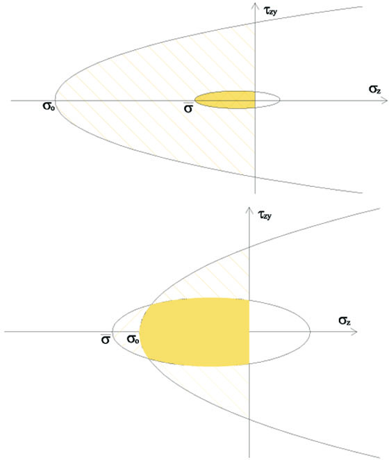
 and b)
  .
.It is worth emphasizing that the strength domain Ɗ differs substantially from the one obtained by applying the Mohr-Coulomb criterion solely to the shear stress τzy acting on the panel’s horizontal planes, i.e. on the beam’s cross-section. In other words, the proposed model differs greatly from that accounting only for horizontal bed joint sliding. Fig. (6) shows a comparison.
According to the strength domain assumed and, as already stated, referring to the case Ɗ ≡ Ɗ1 for the sake of simplicity, the constitutive equation can be written as follows:
 |
(13) |
with  and E the Young’s modulus; moreover, let
 |
(14) |
so that Eq. (9) can be written as  , and denoting
 |
(15) |
with G the shear modulus, the constitutive law for the tangential stress turns out to be
 |
(16) |
3. BEHAVIOR OF THE BEAM’S CROSS SECTION
Given the kinematic assumptions set forth in Section 2.1 and the assumed constitutive law, the normal stress σz has a piecewise linear diagram over any rectangular cross section and can be determined. Various possible σz patterns can occur, each of which corresponds to a different region in the plane of the generalized strains (ε, κ).
This constitutive equation has been presented in details in [16] for the simpler case in which the effects of shear deformation can be neglected and is not provided herein for the sake of brevity.
As regards the τzy patterns, some clarification is in order. It is firstly worth noting that, once the values of the parameters τo and m are fixed, the strength domain given by Eq. (9) is a function of σz alone; hence, in view of Eqs. (13) and (3),  turns out to be a function of two generalized strain only, i.e.
 .
.
Furthermore, it is a simple matter to verifiy that, for a fixed pair of values of ε and κ,  , depends on the y-coordinate with the same law of dependence on σz. Thus, the shear stress boundary
  (y) is still an ellipse over the beam cross-section, with center C and half major axis a equal to:
 |
(17) |
The intersections of the ellipse with the y-axis may or may not fall within the cross-section, depending on the values of ε, κ, in addition to those of the mechanical parameters E, m and τo, as shown by the following examples.
Lastly, from Eq. (16) and assuming for the sake of simplicity that the shear strain of each fiber is equal to an average value given by the generalized strain, i.e. γzy = γ, the shear stress τzy turn out to be a function of ε, κ and γ, i.e. τzy = τzy(ε, κ, γ).
Overall, many situations must be considered in order to define the patterns of the axial and tangential component σz and τzy, depending on the values of ε, κ and γ. Some of those deemed more significant are shown by way of example in the following.
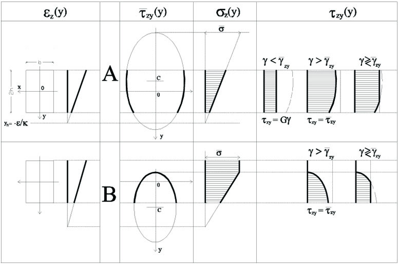
With reference to a rectangular cross-section of dimensions b and 2h, let us suppose that κ > 0 and the section is not partialized i.e. the εz pattern is the one shown in Fig. (7), where the neutral axis  does not cross the section.
In view of Eq. (17), the ordinate of the vertices of ellipse  (y) must always be on the opposite sides with respect to yn. Hence, in this case, with yn > h, two qualitatively different circumstances can occurr depending on the values of ε and κ: both vertices of
  fall outside the section, or just one of them, as shown in Fig. (7) respectively in rows A and B, together with the corresponding σz pattern. Moreover, by simply comparing γ to
  of Eq. (15), any possible τzy pattern can also be obtained, as shown in the Fig. (7).
Essentially, different situations, leading to different τzy pattern, can occurr. With reference to the situation shown in row A of Fig. (7), it may turn out that γ≤ over the whole cross-section, i.e. for any y ϵ [-h,h], so that τzy (y)= Gγ; or we can have γ>
 over the whole cross-section, and in this case τzy(y) =
  (y); lastly, γ>
 may hold solely over a part of the section, with the consequent τzy pattern shown in Fig. (7). It is worth just noting that, in case of different positions of the ellipse with respect to the cross-section i.e. for various different values of of the strains (ε,κ)-, the latter situation
  may provide further possible τzy pattern, not shown for the sake of brevity.
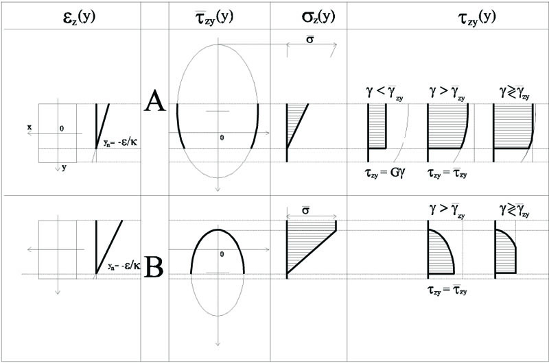
Similar situations can occur if the section is partialized, as shown in Fig. (8). Note that some situations, such as the entirely elastic case, are not consistent with the position of the ellipse and, thus, can not occurr.
Finally, once the σz and τzy patterns are known, for any value of (ε, κ, γ), the generalized stress -N, V and M are determined as
 |
(18) |
4. NUMERICAL RESULTS
The proposed model has been implemented into the finite element code MADY [12]. To obtain a locking-free Timoshenko beam element, only one Gauss point has been used for the numerical integration [28]. For the rest, the numerical procedure used is standard and has been described in detail elsewhere [12, 15, 16, 29], with reference to other types of “beam” elements.
To highlight the ability of the proposed beam model to capture the in-plane behaviour of masonry panels, some comparisons have been conducted with the numerical results obtained by means of two different 2D finite element models.
The first bi-dimensional model used has been developed by the authors themselves and is presented in detail in [26]. The model is an extension of the classical masonry-like or no-tension model [30, 31]: besides limiting the compressive strength, the model accounts, for a bound to the shear stress component on each plane, that depends on the acting normal stress component. With reference to shear, the idea of the material constitutive behaviour is, therefore, the same used for developing the proposed beam model. Naturally, the two models differ essentially in the kinematic constraints and the consequent stress state given by Eq. 7. Moreover, they differ with regard to the hypothesis on the cohesive force acting on the cracked parts of the structure, being nil in the beam model but provided for the 2D model. The 2D model has been implemented into the code MADY and has been used in the following analyses with four-node elements in the plane stress framework.
The second model used a 2D model available within the FE commercial code ANSYS. Specifically, 2D geometries under the assumption of plane stress have been discretized by using PLANE182 finite elements, while the Mohr-Coulomb model with cut-off has been selected to represent the masonry’s constitutive behavior [25].
It is also worth mentioning that the constitutive law of the two 2D models used are similar but not equivalent [32].
4.1. Comparisons for Single Panels
In this section, some comparisons with experimental results for a single panel are provided. Specifically, referring to the experimental research conducted at the Joint Research Centre in Ispra in 1995 [10, 24, 33-36], two geometries have been considered: A squat panel with 1.35 m height, and a slender panel with 2.0 m height, both of them having a rectangular cross-section 1 m in width and 0.25 m in thickness. As in the experimental tests, the panels are perfectly clamped at their base, with a further restraint to rotation at the top. Moreover, they have first been subjected to a constant vertical load P equal to 150kN, which entails a normal compressive stress σz equal to -0.6MPa. The self-weight has also been considered, assuming for the mass density a value ρ = 1800 kg/m3 [24]. Then, all the analyses have been conducted by applying a monotonic increasing horizontal displacement at the top of the panels.
As per to some indications given in the literature [10, 24, 36], the main mechanical characteristics assumed are as follows: E = 1800MPa, G = 820MPa (i.e.ν = 0.1), σo = -6.2MPa, and for shear, the values τo = 0.72MPa and m = -0.4, have been chosen. It is worth noting that such values are reasonable, and fall within the range of values assumed in the aforementioned research papers to calibrate other numerical models. Naturally, the issue of assuming appropriate values for these material parameters is an open one, which requires comparisons with a large amount of experimental data, a task which is beyond the scope of the present paper.
For the numerical simulations, both panels have been discretized into 80 beam elements. The number of finite elements has been chosen to obtain the most accurate response provided by the model, also in view of the comparisons of the stress state given by the more refined 2D models. Decreasing the element number – down to very few elements, has shown to cause slight variations in the results – which are in any case conservative; conversely increasing the number of finite elements has not lead to any significant variation.
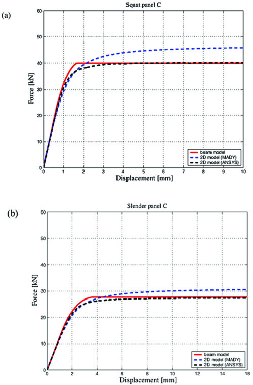
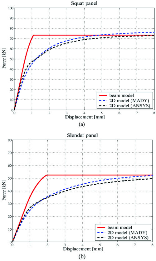
The global response of the analysed panels has been presented through pushover curves, i.e. shear force vs top displacement curves. Fig. (9a) shows the results obtained for the squat panel. The analogous diagrams for the slender panel are shown in Fig. (9b).
As shown in Figs. (9a and b), the responses obtained via the beam model are consistent with those from the 2D-models. Unsurprisingly, the response obtained via the beam model exhibits a slightly larger global stiffness with respect to that predicted through the 2D models. Nevertheless, the predicted total lateral strength of the panels are in very good agreement. It is quite interesting to note that no significant variation in the agreement of results emerges between the two structural cases considered, that is by varying the slenderness of the panels.
The accuracy of the beam model’s predictions has been also verified from a local perspective. With reference to the squat case, Figs. (10a and b) provide a comparison with results obtained via the 2D models, respectively in terms of minimum principal stress σmin - previously denoted by σ- – and maximum shear stress τmax attained throughout the panel. Such comparison is carried out at the loading step where a displacement of 5 mm is attained.
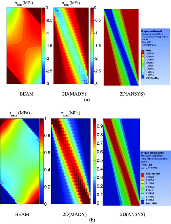
As shown in Fig. (10), the beam model yields quite a different result in terms of stress state, despite the similar global response depicted in Fig. (9). The degree of stresses achieved at the top and the base of the panel provided by the beam model is acceptable, if compared with those predicted by the 2D models. However, the predicted stress state throughout the panel is more widespread if compared to that given by the two 2D models, which is confined to a limited area along the diagonal of the panel. Such a distribution cannot be captured by the beam model due to the embedded kinematic contraints.
Like the global responses, the local results for the slender panel are also qualitatively similar to the analogous ones shown in Fig. (10) for the squat case, and hence have not been presented here for the sake of brevity.
In the following, some further comparisons have been carried out by varying the boundary conditions, as they have proven to affect the panels response significantly.
Specifically, for each geometry, the following boundary conditions - widely assumed to represent the actual constraints in real buildings - have also been considered:
- the panels are perfectly constrained at the base and totally free at the top, a condition that in the following will be referred to as C, i.e. cantilever;
- the panels, still clamped at their base, have further restraints on the axial displacement and rotation at the top nodes after application of the vertical load; such cases will be referred to as DF, which stands for double fixed.
Figs. (11a and b) show the pushover curves for the squat and the slender cantilevers (C panels), respectively. The trends of the results are similar to those already shown in Figs. (9a and b), thus confirming the ability of the simple model to provide an acceptable picture of the global response.
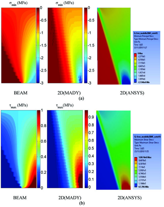
Fig. (12) shows the results obtained for the C slender panel in terms of stress state. In this case, contrary to what happens with the panel when top rotation is constrained, the proposed model appears to be more accurate in describing the state of stress in the panel body. Indeed, the stress state prediction is quite satisfactory if compared to that given by the 2D models. Results for the C squat panel are substantially similar and thus omitted here.
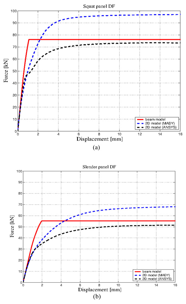
Fig. (13), where results analogous to those in Fig. (11) are illustrated for the DF panels, substantially confirms the previously revealed trends. The beam model provides an accurate prediction of the global response of the panel.
From a local point of view, trends qualitatively similar to Fig. (10) emerge from the DF panels stress state, not reported here.
4.2. A Wall with an Opening
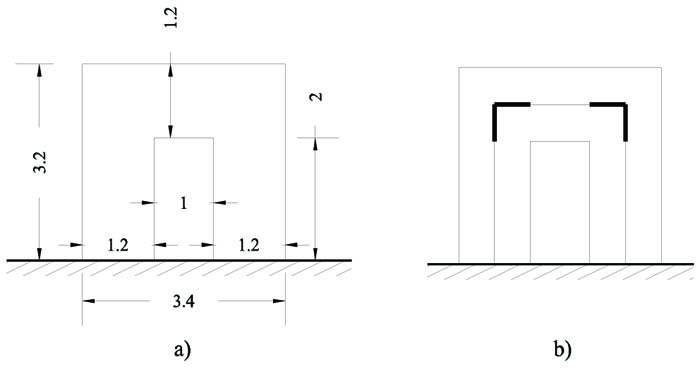
Simplified models are especially useful for analyzing more complex structures than simple panels, for which sophisticated models may involve very high computational costs. Hence, in order to highlight the possible use of the proposed model in practical applications, some preliminary results are presented for an idealized masonry wall, provided for illustrative purposes only. In this framework, the wall is represented as an idealized frame, in which the piers and spandrels are connected through rigid offsets.
More in detail, the analysed structure is a wall with a centered opening (Fig. 14). The wall’s main geometrical characteristics are as follows: height = 3.2 m, width = 3.4 m and thickness = 0.25 m, while the dimensions of the opening are 2 x 1 m. As for the mechanical properties, the values used in the foregoing have been assumed, i.e. ρ = 1800kg/m3, E = 1800MPa, ν = 0.1, σo = -6.2MPa, and τo = -0.72MPa and m = -0.4.
In addition to the self-weight, a distributed vertical load - with total resultant of 220kN- is firstly applied at the top of the wall; then, it is subjected to an increasing horizontal displacement, keeping rotation at the top costrained.
A sketch of the idealized wall used in the finite element analysis is depicted in Fig. (14). The dimensions of the rigid nodes have been defined according to the relevant literature [2].
Using the proposed beam model, each pier has been modeled through 40 finite elements, while the spandrel has been discretized into 20 elements. Each node is instead represented by 6 (vertical) plus 6 (horizontal) rigid beam elements.
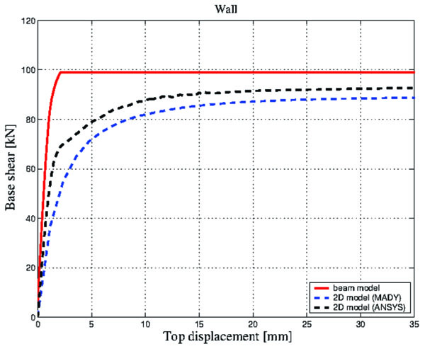
The results have been compared with those obtained with the 2D models used in the foregoing, i.e. the masonry-like model implemented in MADY and the one available in ANSYS, assuming the same mechanical properties, load and constraint conditions.
Fig. (15), which shows the total base shear vs top displacement curves obtained via the three models, highlights a consistent trend with some slight difference in the total lateral capacity.
Obviously, although some promising results have been obtained, a number of issues still remain to be settled in order to enable using the proposed model for the analyses of real masonry structures, especially with regards to defining the behavior and geometries of the spandrels and rigid offsets.
CONCLUSION
The need to preserve an enormous heritage of masonry buildings, which as demonstrated by recent seismic events are extremely vulnerable to horizontal actions, calls for simplified models and low-computation numerical methods to perform preliminary and/or wide-area investigations.
It is to this end that a refined beam model has been proposed. Starting with a no-tension material approach, the model has been enhanced by endowing it with the ability to describe shear behavior and predict the collapse mechanisms typically exhibited by relatively squat panels loaded in their plane.
Some comparisons with the results obtained through two different 2D models (which also account for a limit to shear stress) have been conducted to evaluate the accuracy of the results predicted by the proposed model. Despite its simplicity, the beam model is quite capable of capturing the panels global response. This is true regardless of the slenderness and constraint conditions.
The model can also provide some broad indications on the local stress distribution in the panels. Also from a local perspective, the predictive capacity of the model is practically independent of the slenderness of the walls. Conversely, the accuracy of these results is affected by the panel’s constraint conditions, being more acceptable for panels which are free at the top.
Lastly, some preliminary results have also been carried out for an idealized wall with an opening, in order to show the possible application of the proposed model to assess the seismic capacity of a masonry wall and facade through non-linear static analyses.
NOTATIONS
| (o, y, z) | = Reference system |
| b | = Width of the beam’s rectangular cross-section |
| 2h | = Height of the beam’s rectangular cross-section |
| n | = Normal unit vector |
| σn | = Normal component of the stress |
| τn | = Tangential component of the stress |
| T | = Stress tensor |
| σy, σz, τzy | = Stress components |
| σ-, σ+ | = Principal stresses |
| εy, εz, γzy | = Strain components |
| σo | = Minimum compressive stress |
| τo | = Cohesion |
| m | = Internal friction |
| ρ | = Density |
| E | = Young’s modulus |
| G | = Stress tensor |
| ν | = Poisson’s ratio |
| ε, κ, γ | = Generalized strain |
| N, V, M | = Generalized stress |
| u, v | = Displacement component of the beam’s axis |
| φ | = Rotation of the cross-section |
CONSENT FOR PUBLICATION
Not applicable.
CONFLICT OF INTEREST
The authors declare no conflict of interest, financial or otherwise.
ACKNOWLEDGEMENTS
Declared none.


