All published articles of this journal are available on ScienceDirect.
Double-Leaf Infill Masonry Walls Cyclic In-Plane Behaviour: Experimental and Numerical Investigation
Abstract
Background:
The infill masonry walls are widely used in the construction of reinforced concrete buildings for different reasons (partition, thermal and acoustic demands). Since the ‘60s decade, one of the most common typology in the southern Europe was the double-leaf infill walls. Recent earthquake events proved that this specific typology have an important role in the seismic response of reinforced concrete structures in terms of stiffness, strength and failure mechanisms. However, modelling approaches of these specific infill panels cannot be found over the literature.
Objective:
Due to this, the major goal of the present manuscript is to present a simplified modelling strategy to simulate the double-leaf infill masonry walls seismic behaviour in the software OpenSees.
Method:
For this, two different modelling strategies were proposed, namely through a global and an individual modelling of the panels. An equivalent double-strut model was assumed and both strategies were compared and calibrated with experimental results from a full-scale in-plane test of a double-leaf infill masonry wall.
Results:
The numerical results obtained by each strategy are very accurate in terms of prediction of the specimen’ initial stiffness, maximum strength and strength degradation.
Conclusion:
From the force evolution throughout the tests, it was observed differences lower than 10%. Globally, the individual modelling approach reached better results.
1. INTRODUCTION
The Infill Masonry (IM) walls are used in Portugal since the sixty’s decade due to architectural and functionality issues. However, in the structural design the infills are considered non-structural elements and the lateral stiffness and strength contribution is neglected. Only the gravity load is considered in most of the international structural design codes. However, recent earthquakes around the world have shown that these elements can increase the seismic vulnerability of some structures or structural elements. Several reports of extensive damages and collapses observed in reinforced concrete structures have been reported by the presence of the IM walls [1-6].
The infill panels interact directly with the surrounding RC frame when subjected to a lateral loading, such as wind load or seismic loading. It is widely known that the presence of infills increases significantly the structural stiffness and changes consequently the natural period of the structure, which increases the expected seismic demand [7]. The structural strength, ductility and energy dissipation capacity of the building is also affected according to some research investigations [8-11].
Failure mechanisms such as short-column, or soft-storey or torsion can play an important role in the seismic response of the structures. Different details can trigger these phenomena, namely:
- existence of openings that can introduce high shear stresses to the surrounding columns, which were not designed to support;
- Vertical stiffness irregularity due to the non-uniform vertical distribution of the IM walls that can result in excessive displacements on the storeys with less infill panels [12];
- irregular plan distribution of the IM walls, which can result on torsional failure of the building and also to the increase of the corner columns stresses [13, 14].
Regarding the Portuguese construction scenario, the clay bricks with horizontal perforation are by far the most widespread masonry units used and are present in many structural systems. Different constructive IM walls typologies can be found around the Portuguese building stock, as illustrated in Fig. (1). Starting from the ‘40s decade, the typical partition wall used was composed by stone masonry units with large thickness (mostly of the times used as structural elements). During the ‘50s decade the double-leaf wall was introduced, with and without air box between the external and internal leaf. In most of the times, both leafs were composed by stone masonry, however sometimes the internal leaf was made by clay bricks. In the ‘60s decade, a significant increase of the RC structures number was observed in which the façades were composed of double-leaf IM walls. The main difference observed in the ‘70s decade was the reduction of the external leaf thickness (Fig. 1). The use of thermal isolation to fill totally or partially the air box between the internal and the external leaf was very common throughout the 80s.
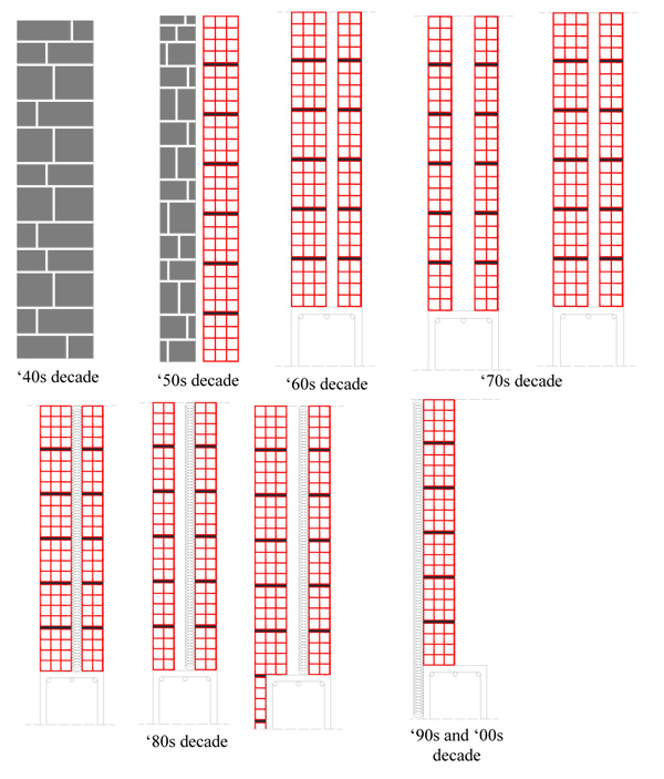
Finally, the main difference observed in the ‘90s decade was that the buildings’ façades were composed of one-leaf infill panels with the external face covered by thermal insulation and connected to the RC elements to. The panels’ representative of the ‘50s, ‘60s, ‘70s and ‘80s decades were not built with connection to the RC elements. Nowadays, the building’s façade is made by one single leaf with external thermal isolation connected to the infill panel and to the RC elements. Similar evolution of the IM walls construction typology was observed in the Southern European Countries.
Regarding the recent research works related to the seismic performance of the IM walls, some authors focused on the contribution of these elements in the seismic performance of structures [15-17]. The infill panels increase the lateral global stiffness and strength which modify the period of the structure and thus increase the expected seismic demand according to the response spectra as proved by the following research works [18-21]. Some authors highlighted the large increase of the shear forces that the adjacent columns are subjected to, leading to shear failures of these elements. Some prediction of the additional shear forces provided by the infill panels can be found in [22-24]. Recently, some authors focused on the direction of the IM research topic in the in-plane/out-of-plane behaviour interaction. The poor out-of-plane seismic behaviour of the infill walls in recent earthquakes with innumerous collapses was reported as well as the high contribution of the previous damage (due to in-plane demands) that increased the out-of-plane vulnerability of the panels [25-27]. Recent, simplified macro-modelling approaches were proposed considering this combined behaviour [28-32]. Several efforts have been performed in the realization of different experimental campaigns, both concerning the in-plane and out-of-plane response of IM walls [33-35].
For a better characterization of the in-plane performance of one of the most representative typologies, a full-scale double-leaf infill panel was subjected to an in-plane cyclic test.
This test was included in research project with the major goal to characterize the out-of-plane performance of the IM walls with previous damage caused by an in-plane demand. This specimen was first subjected to a cyclic in-plane test until reaching a maximum lateral drift of 0.5%. After that, the interior panel was removed and the external damaged panel was subjected to cyclic out-of-plane load until de rupture. The main scope of this study is the in-plane test of the double-leaf IM wall, since there is no data available in the literature concerning this wall typology. Throughout the manuscript, the main test results and findings will be presented and discussed in terms of hysteretic force-displacement curves, cracking pattern, secant stiffness degradation and cumulative energy dissipation. More details concerning the out-of-plane test can be found in [36].
The major goal of this research work is to present a simplified numerical modelling approach to simulate the double-leaf infill panels in-plane behaviour. The discussion regarding the modelling strategies and assumptions will be detailed throughout the manuscript. The calibration of the numerical approach with the experimental test results will be presented in terms of force-displacement hysteretic response, evolution of the force along the test, maximum strength and energy dissipation.
2. IN-PLANE TEST OF A FULL-SCALE DOUBLE-LEAF IM WALL
2.1. Specimen Description
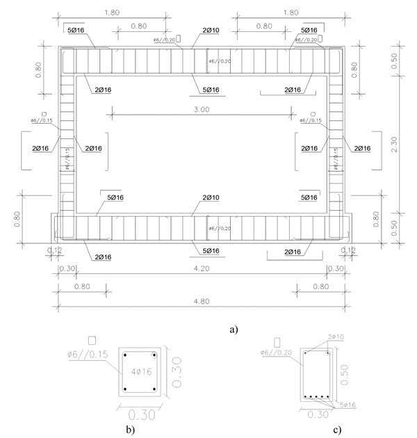
One full-scale RC frame filled with a double-leaf infill panel was subjected to cyclic in-plane loading test. The general dimensions of the specimen are 4.80x3.30m2 and the columns and beams cross sections are 0.30x0.30m2 and 0.30x0.50 m2, respectively, which are representative of those existing in the Portuguese building stock [37]. Fig. (2) shows the RC infilled frame geometry, as well as the corresponding columns and beams dimensions and reinforcement detailing. The columns and beams dimensions are presented in Figs. (2b and 2c).
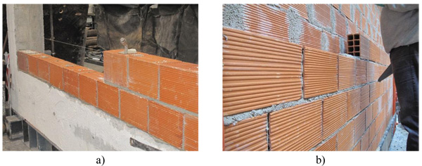
The full-scale double-leaf panel is composed by an external leaf with 15cm thickness and an internal leaf, of 11 cm thick, was added aligned with internal side of the beam, leaving a gap thickness of 4cm. Images from the construction process of the IM wall are illustrated in Fig. (3). No connection between the panels and the frame were used [38].
2.2. Material Characterization
2.2.1. Concrete and Re-Bars Properties
The material ordered for the RC frame specimen construction consisted on regular C20/25 class concrete and A500 steel class [39]. Considering a conversion factor of 0.8 to convert (approximately) the mean cubic compressive strength, it yields fcm,cyl=21.4MPa. Then assuming the approximate relation fck,cyl= fcm,cyl=8MPa, which estimates the characteristic value of the compressive strength, it is obtained the fck,cyl=13.4MPa. From the compressive strength tests, it was found an ultimate compressive strength of 26.8MPa and a concrete elasticity modulus of 24.7GPa.
| Diameter Group | Young Modulus E (GPa) | Yielding Strength Fsy (MPa) | Ultimate Strength Fsu (MPa) | Ultimate Strain εsu (%) |
|---|---|---|---|---|
| 6mm | 204.2 | 444.0 | 593.2 | 16.4 |
| 10mm | 209.7 | 598.9 | 698.2 | 19.9 |
| 16mm | 209.4 | 494.4 | 615.0 | 26.2 |
| Type of Test | fm | Em | ||
|---|---|---|---|---|
| Mean (MPa) | COV (%) | Mean (MPa) | COV (%) | |
| Compressive strength | 1.1 | 11.3 | 941.9 | 24.8 |
| Diagonal shear | 0.60 | 20.1 | - | - |
| Parallel flexural | 0.11 | 43 | - | - |
| Perpendicular flexural | 0.379 | 9.5 | - | - |
For the RC frame specimen construction three different bars diameters were used, from the same lot, namely 6mm, 10mm and 16mm. Three samples of each one were taken from each diameter bar and tested according to [40]. The relevant results obtained are summarized in Tables 1 and 2, in terms of young modulus, yielding strength, ultimate strength and ultimate Strain, for each sample and for the corresponding average value of each bar diameter.
2.2.2. Masonry Properties
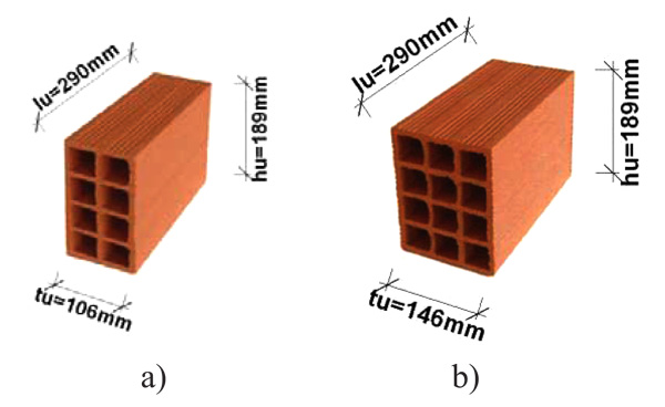
The selected masonry typology represents the commonly clay bricks used in the Southern Europe region with horizontal perforation, with the geometric properties illustrated in Fig. (4). Two different masonry units were adopted, varying only the thickness (150mm and 110mm). A traditional mortar M5 (Ciarga) class was considered for the construction of the panels. The thickness of the bed joints adopted were 1cm for the vertical and the horizontal ones. The contact between the panels and the RC elements was achieved by thin layer of mortar. No mechanical connection was considered. The flexure and the compressive mortar tests were performed (6 samples from each panel). The main results obtained were a mean flexural and compressive strength of 4.27MPa and 13.4MPa respectively.
Mechanical characterization tests were performed in masonry wallets of both brick type to obtain further information about the properties such as compressive strength, diagonal shear strength, parallel and perpendicular flexural strength and are illustrated in Tables 3 and 4 respectively.
| Type of Test | fm | Em | ||
|---|---|---|---|---|
| Mean (MPa) | COV (%) | Mean (MPa) | COV (%) | |
| Compressive strength | 0.7 | 18.8 | 854.5 | 39 |
| Diagonal shear | 0.60 | 34.7 | - | - |
| Parallel flexural | 0.121 | 3.9 | - | - |
| Perpendicular flexural | 0.321 | 19 | - | - |
2.3. Test Setup Detailing
The in-plane test consisted on the application of a horizontal force on the top of the RC frame using a servo-controlled hydraulic actuator (+/-500kN capacity with +/-150mm stroke) attached to a steel reaction structure (Fig. 5). The horizontal force was transmitted to the RC frame by two high strength rods (ø22mm) (in the front and rear specimen sides) tying two steel shapes at the left and right extremities of the top beam, to apply in-plane loading cycle reversals. The two high strength rods were linked at 1/4, 1/2 and 3/4 of the beam length to steel plates that connect with the corresponding one of the other side of the beam by 2 steel rods (ø10mm) with the main objective of mobilize and distribute the in-plane load along the entire top beam cross-section uniformly.
| fc(MPa) | dc (%) | fy (MPa) | dy (%) | fmax (MPa) | dmax (%) | fu (MPa) | du (%) |
|---|---|---|---|---|---|---|---|
| 0.58 | 0.11 | 0.75 | 0.21 | 1.67 | 0.43 | 0.28 | 1.5 |
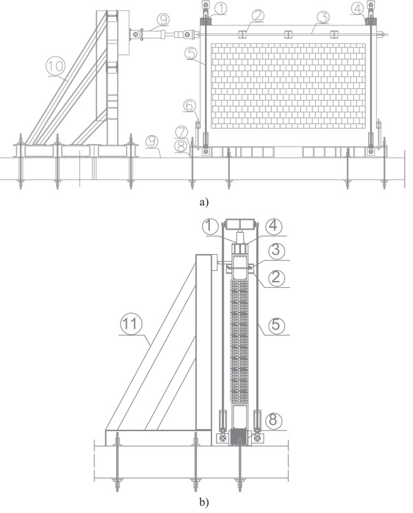
The column axial load was applied using one hydraulic jack in the top of each column, attached to the top and bottom of the steel devices by means of high-strength rods with hinged extremities. The in-plane infilled frame was tested under the so-applied column axial load of 270kN kept constant with the prescribed value measured by load cells attached to the jacks (Fig. 6). The test set-up was also provided with an additional guiding structure to prevent out-of-plane displacements of the infilled RC frame, while allowing it to slide along the steel shape guides [41].
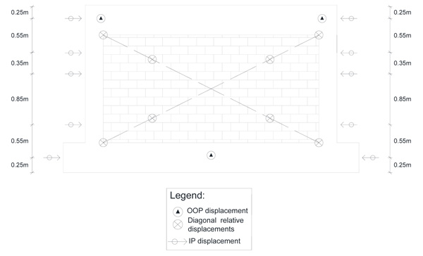
2.4. Instrumentation and Loading Condition
The instrumentation was composed by a total of 21 displacement transducers, both Linear Variable Displacement Transducers (LVDTs) and Draw Wire Transducers (DWT) (Fig. 6). The instrumentation was divided in 3 different groups according to the corresponding measurement objective: i) out-of-plane displacements of the infilled RC frame (3 LVDTs); ii) diagonal displacements of the panels and of the RC frame (8 DWTs) in both specimen sides and iii) in-plane displacements of the infilled RC frame (10 LVDTs). Besides the additional guiding structure to prevent the out-of-plane displacements, it was included the three LVDT for redundancy and to ensure the absence of this phenomenon.
The aim of the present experimental campaign is to better understand the in-plane behaviour of double-leaf IM walls. To this end, cyclic in-plane displacements were imposed at the top of the IM wall with steadily increasing displacement levels. Aiming at subjecting the IM wall to 0.5% maximum in-plane drift, the following nominal peak displacement levels (mm) were considered: 2.5, 3.5, 9, 12 and 15, with 3 cycle repetitions for each displacement level.
2.5. Experimental Results
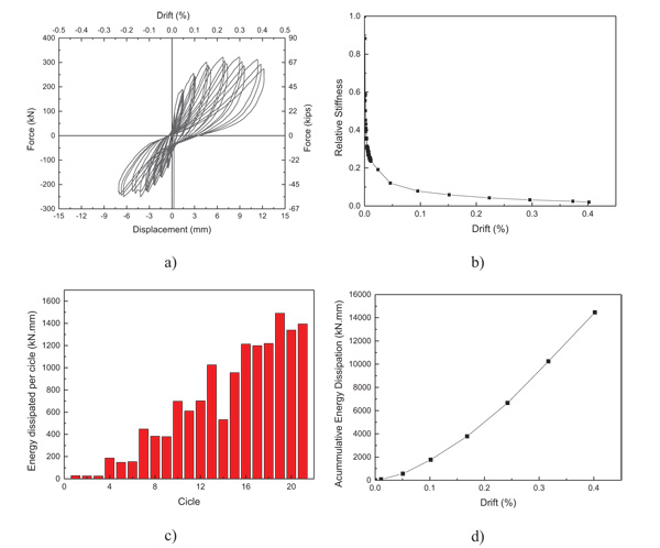
The experimental results will be presented in terms of shear-drift hysteretic curve, secant stiffness, energy dissipation per cycle and accumulated energy dissipation. From the analysis of the test results, the following observations can be drawn:
- The shear-drift curve obtained is asymmetric since it occurred extension of the longitudinal high-strength rod in the negative direction. Due to this, the positive direction of the loading will be adopted as reference. It was observed along the test a continuous increase of the strength until 0.25% (Fig. 7a) drift, after which the strength stabilized, without being observed any strength degradation along the test.
- The maximum strength was characterized by the onset of diagonal cracking in the weaker panel (110 mm thick) and detachment of the surrounding RC frame. At the 0.3% drift it was possible to observe panels’ detachment relative to the top beam and corner crushing in the stronger panel (Fig. 8).
- Regarding the relative stiffness (Fig. 7b) it is observed a significant degradation until reach 0.05% of drift and thus maintains constant until the end of the test.
- From the observation of the energy dissipated per cyclic throughout the tests, it can be observed that is dissipated more energy in the first cycle per peak displacement (Figs. 7c and 7d) except for the first three cycles where it was achieved the same values and for a drift equal to 0.33%. After reached 0.17% drift, it can be observed that the third cycle of the same peak displacement reach higher energy dissipation than the second cycle.
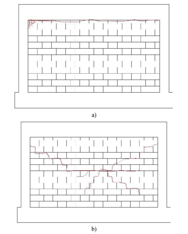
The major damages observed were the detachment of the panel of the surrounding RC frame for a drift equal to 0.20% and corner crushing of the external leaf (Fig. 8). Regarding to the internal leaf it was observed only diagonal cracking in and local crushing in the central upper zone of the panel, as illustrated in Fig. (8).
3. SIMPLIFIED NUMERICAL MODELLING APPROACH FOR DOUBLE-LEAF IM WALLS
3.1. Simplified Macro-Model Description and Framework
The simplified macro-model presented here to be applied in OpenSees software [42] to represent masonry infill walls is an improvement of the commonly used equivalent bi-diagonal strut model, frequently used to represent the infill panels’ nonlinear behavior when subjected to in-plane cyclic loading. In this numerical approach each masonry infill wall is simulated by four diagonal struts with rigid behavior, and a central element where the non-linearity hysteresis is concentrated Fig. (9) [29, 43, 44].
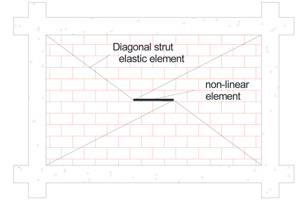
The presented simplified macro-model can be applied in OpenSees [42] with the association of the available OpenSees materials, sections and elements commands. The infill model must be composed by four Elastic Beam Columns for the diagonal elements and by one nonlinear Beam Column element for the central element. The Pinching4 uniaxial material model was used to represent the hysteretic behavior of the infill panel and was attributed for the central element. This uniaxial material is used to construct a material that represents a 'pinched' load-deformation response and exhibits degradation under cyclic loading. Cyclic degradation of strength and stiffness occurs in three ways: unloading stiffness degradation, reloading stiffness degradation, strength degradation. Further details regarding the in-plane calibration of the infills behaviour can be found in [29, 43, 44]. Furtado et al [44] demonstrated that this numerical model approach represents well global response and energy dissipation of the infill panel when subjected to horizontal loadings. This model is also able to consider the out-of-plane of the infill panel during a non-linear analysis and in particular the interaction between the in-plane and the out-of-plane behaviour of the panel [29].
3.2. Double-Leaf Infill Walls Modelling Strategy
Two different strategies were adopted in the present study to represent the cyclic in-plane test of the double-leaf infill wall tested. The first strategy consisted on modelling the double-leaf panel as a single equivalent wall, where it was considered a thickness equal to the sum of the two panels. It was also considered the sum of both infill panels mechanical properties. The second methodology consisted on modelling the double-leaf panel as the composition of two independent panels with each mechanical property. The numerical modelling parameters presented bellow were determined by comparing the numerical results with the experimental ones and by optimizing them.
3.2.1. Strategy 1 – Global Modelling Approach (GMA)
In this numerical approach it was considered an equivalent one-leaf panel with the thickness and compressive strength determined as the sum of the interior and external panel corresponding values. Considering this, it was defined the hysteretic penta-linear curve (Table 4). The input modelling parameters used in the definition of the penta-linear curve defined by eight parameters, are: a) cracking (force Fc and drift dc); b) yielding (force Fy and drift dy); c) maximum strength, corresponding to the beginning of crushing (Force Fcr and drift dcr); d) residual strength (force Fu and drift du).
3.2.2. Strategy 2 – Individual Modelling Approach (IMA)
The modelling of the two infill walls at the same time with the respective geometric and mechanical properties was considered in this numerical approach. For the external leaf, a panel thickness for the numerical model of 150mm and a compressive strength of 1.1 MPa were considered. Otherwise for the internal leaf, a panel thickness for the numerical model of 110mm and a compressive strength of 0.7 MPa was considered. Thus, it was defined that the penta-linear curves for both panels, and the parameters used for the numerical modelling are summarized in Table 5.
| Leaf | fc(MPa) | dc (%) | fy (MPa) | dy (%) | fmax (MPa) | dmax (%) | fu (MPa) | du (%) |
|---|---|---|---|---|---|---|---|---|
| External | 0.37 | 0.1 | 0.65 | 0.25 | 1.01 | 0.5 | 0.28 | 1.5 |
| internal | 0.21 | 0.1 | 0.43 | 0.25 | 0.89 | 0.5 | 0.16 | 1.5 |
3.3. Discussion of Results
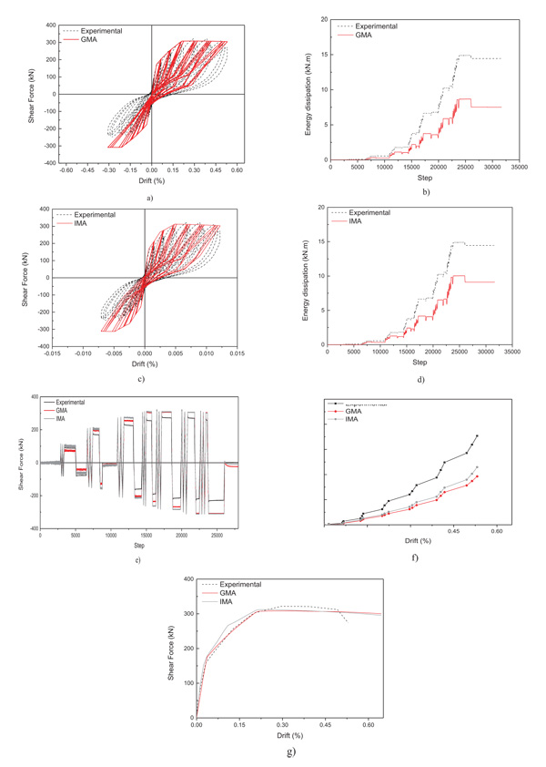
For the present study it was intended to perform the comparison between the numerical and the experimental results only for the positive direction of the test, due to the difficulties to represent numerically the problems that caused the asymmetric results between the positive and negative directions. It was performed the comparison in terms of shear-drift hysteretic curves (Figs. 10a and 10c), evolution of the forces (Fig. 10e), accumulated energy dissipation (Figs. 10b, 10c and 10d) and shear-drift envelopes (Fig. 10g).
From the numerical results it is possible to conclude that the results are quite similar, however some differences were found, namely IMA approach achieved better results compared with the GMA in terms of initial stiffness and maximum strength. Both approaches revealed a good fit of charge stiffness during all the tests, however the unloading stiffness did not capture very well the experimental results with differences around 15-40%. The evolution of the forces along the test, plotted in (Fig. 10c) shows that globally the numerical approaches fitted the experimental results with differences less than 10%.
As stated before, the IMA approach revealed to represent with better accuracy the experimental test and the accumulated energy dissipation demonstrates that with less differences than the GMA approach. It is observed that for lower drift values the numerical models represented satisfactory the energy dissipation capacity of the IM wall, however due to the asymmetry of the results for larger drift demands the numerical models did not capture with the same accuracy reaching differences about 40% and 45% for the IMA and GMA approaches respectively (Fig. 10f).
Finally, the shear-drift enveloped (Fig. 10g) for the positive direction of the test demonstrates the good accuracy of the numerical model to represent the initial stiffness, maximum strength and maximum strength degradation observed along the test.
CONCLUSION
The major goals of the manuscript were: i) experimental characterization of the in-plane behaviour of a full-scale double leaf IM wall; and ii) proposal of a numerical modelling approach to simulate the in-plane cyclic behaviour of IM walls.
From this experimental test, it was observed that the force-displacement curve was asymmetric between the positive and negative loading direction. This fact was due to the extension of the longitudinal high-strength rods in the negative loading direction. This detail conditioned partially the test results, since only the positive loading direction can be assumed as the reference result.
From the test it was observed that a continuous strength increases until reaching 0.25% of drift. After that, no significative changes were observed in terms of strength degradation until 0.5% drift. The specimen reached the maximum strength at the same moment that was visible as a diagonal cracking and detachment of the panel from the RC frame of the interior leaf (t=110 mm). The visible damages observed in the larger panel (t=150mm) occurred for 0.3% of drift with detachment of the panel from the surrounding frame and corner crushing. The panel stiffness suffered a significant degradation until reaching 0.05% of drift. Finally, it was observed that it dissipated more energy in the first cycle per peak displacement and after reaching 0.25% in-plane drift.
Two different numerical modelling approaches were presented and discussed namely, a global modelling approach (GMA) considering an equivalent single IM wall that represents global behaviour of the infilled frame, and an individual modelling approach (IMA) that can represent the independent behaviour of each panel.
The numerical results obtained by each strategy were very positive in terms of accuracy to predict the specimen initial stiffness, maximum strength and strength degradation. Both strategies captured very well the evolution of the forces along the test with slight differences (less than 10%).
The major difference observed was the accumulated energy dissipation that were underestimated by both numerical modeling strategies. This was due to the asymmetry of the test results between the positive and negative loading. Globally, the IMA approach revealed better capacity to represent the in-plane behaviour of the double-leaf IM wall under study. Further studies must be performed in the future to calibrate this modelling approach. This example allows concluding that the simplified macro-models predict the expected behaviour of the double-leaf panels when subjected to in-plane seismic loadings.
CONSENT FOR PUBLICATION
Not applicable.
CONFLICT OF INTEREST
The authors declare no conflict of interest, financial or otherwise.
ACKNOWLEDGEMENTS
The authors would like to acknowledge the technicians of the Laboratory of Earthquake and Structural Engineering (LESE), Mr. Valdemar Luis and Mr. Nuno Pinto for their support in the experimental activity reported in this paper, and Preceram for the provision of all the bricks used in the experimental tests.
This work was financially supported by: Project POCI-01-0145-FEDER-007457 - CONSTRUCT - Institute of R&D In Structures and Construction funded by FEDER funds through COMPETE2020 - Programa Operacional Competitividade e Internacionalização and by national funds through FCT - Fundação para a Ciência e a Tecnologia. This work was object of specific financial support of FCT through the P0CI-01-0145-FEDER-016898 – “ASPASSI Safety Evaluation and Retrofitting of Infill masonry enclosure Walls for Seismic demands”. The authors also acknowledge the constructive comments and suggestions given by the anonymous reviewers which improved the quality of the manuscript.

