All published articles of this journal are available on ScienceDirect.
Investigation on Friction Features of Dissipative Lap Shear Connections by Means of Experimental and Numerical Tests
Abstract
Background:
Beam-to-column joints equipped with friction dampers are a viable solution to improve the dissipative capacity of moment Resisting Frames without any damage after severe seismic events. Recently, novel systems have been developed within the RFCS FREEDAM research project.
Objective:
The objective of the work is to provide a rational selection based on engineering judgment, of possible materials to be used in friction dampers.
Methods:
Both experimental analysis and Finite Element (FE) simulations have been carried out to assess the friction coefficients of several interfaces evaluating also their ability to withstand cyclic loading histories.
Results:
The experimental campaign showed that both hard and soft metals can be used in combination with stainless steel obtaining satisfactory performance under cyclic loads. In addition, at high slip velocities, large temperatures are developed within the specimen. Modelling this effect is crucial as it causes a reduction in the slip force capacity. This is due to the transverse dilatation that initially increases the pressure, while bolt tightening reduces due to elongation of the shank.
Conclusion:
The experimental results, together with other similar data selected from technical literature, have been employed to validate FE models able to simulate the behaviour of lap shear friction connections, showing the influence of different modelling approaches over the simulated data. Subsequently, the validated model has been used to perform a set of simulations devoted to highlight the key parameters affecting the response of the lap shears and the possible strategies to improve the performance of the friction dampers.
1. INTRODUCTION
The work herein presented is part of the activities of a wider research project dealing with the application of slip-critical connections in seismic areas. The aim of such a project is the definition of structural layouts able to overcome destructive seismic events with low yielding or no damage, thanks to the inclusion of friction devices in connections. The benchmark beam-to-column joint under study, to be applied in semi-continuous steel Moment Resisting Frames (MRFs) with partial or equal strength connections [1-4], consists in a modification of the detail of a Double Split Tee joint (DST) where, in place of the bottom Tee, a friction connection [5-11], is realized with a slotted haunch slipping on friction shims pre-stressed with high strength bolts (Fig. 1). With such a type of detail, under seismic actions, the beam is forced to rotate around the pin located at the base of the upper T-stub web and the energy dissipation is provided by the alternate slippage of the lower beam flange on friction shims (Fig. 1).
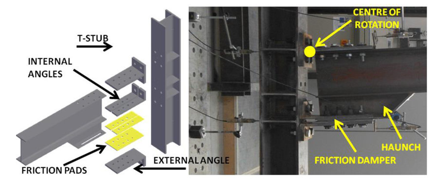
The first studies on such a connection typology can be dated back to the 90s. In these ages, the first prototype of slotted bolted connections was developed in [12] adopting friction interfaces made of mild steel only or mild still and brass. After this pioneering work, many studies were carried out, especially in New Zealand, developing a new generation of friction connections, the so-called “sliding hinge joint” connections which, in order to reduce at minimum the additional costs of the new solution with respect to conventional steelwork, are characterized by extremely simple details based on the inclusion of Asymmetric Friction Connections (AFC) (or also alternatively SFC) at the lower beam flange level with shims made of mild steel, aluminium, brass or, in the most recent version abrasion resistant steel (e.g. [12-17]). Additionally, in 2000, a very similar solution was also patented in Japan [18] based on the previous concept of a friction anti-seismic damper [19-21]. The concept of these joints is very simple and, provided that all the elements of the connection are properly oversized, their inelastic response is mainly governed by the characteristics of the friction damper. Therefore, in order to master the resistance of the sliding hinge friction connection, it is crucial to define as accurately as possible the value of the friction coefficient of the materials employed to realize the damper and to control the preload applied to the friction interface by means of high strength bolts. The bolt pre-loading force can be controlled, as an example, following the European rules, by applying one of the tightening methods suggested by EN1090-2 [22] (i.e. combined, torque, DTI washers). Conversely, the value of the friction coefficient is not easily predictable a priori, due to its dependence on a plurality of factors, and needs to be characterized experimentally. In particular, as already demonstrated in past experimental works, the friction coefficient, obviously, strongly depends on the tribological properties of the materials employed to realize interfaces, such as the superficial finishing, micro and macro hardness, shear resistance and roughness [15, 23, 24].
With the current capabilities, even adopting the most complex tribological models, due to all the complex phenomena involved in the frictional behaviour (wearing, mechanical interlock, adhesion, etc.), it is rather hard to predict the cyclic behaviour of an interface just basing on the knowledge of the mechanical properties of the materials in contact and the surface topography. Additionally, some of the significant parameters are not easy to control or to measure in high detail adopting the normal tolerances of civil engineering practice. As a consequence, in order to get the knowledge needed for the design of connections, it is normally necessary to resort to experimental assessment devoted to provide sets of data correlating, directly, the macroscopic interface features (material typology, superficial finishing, technique adopted to realize the shims) to the observed friction coefficient values. To this scope, currently, a significant work on the characterization of friction materials is ongoing in many research groups worldwide [14,15,24-29], with the aim to define possible interfaces able to provide a proper and predictable hysteretic response. In recent works of the same authors [10,23], experimental analyses on friction interfaces have been carried out on several materials trying to calibrate predictive models and to individuate the key aspects affecting the response of the friction connections.
Within this framework, the aim of the paper hereinafter reported is to present some new experimental and FE results regarding the characterization of the friction behaviour of a set of interfaces under quasi-static cyclic loading conditions. The experimental work, which is herein summarized, regards 13 specimens and eight different materials (identified with the tags M1-M8). The experimental results, together with other similar data selected from technical literature, are employed to validate FE models able to simulate the behaviour of elementary lap shear friction connections showing the influence of different modelling approaches over the simulated data. Afterward, the validated model is used to perform a set of simulations highlighting the main parameters influencing the response of the connection.
2. TESTING PROGRAM
2.1. Tested Friction Interfaces
The tested sub-assemblies regard, as explained in higher detail in next section, elementary lap shear friction connections with two bolts which, similarly to the dampers of a Symmetrical Friction Connection (SFC), are realized combining a slotted steel plate with friction shims made of mild steel coated with one of the materials subsequently described. The materials employed to coat the shims are selected in order to provide to the interface high values of the friction coefficient, with minimum deterioration, guaranteeing contemporarily the durability. Pursuing this objective, in principle, the selected materials have to be corrosion resistant and, based on previous experience [15, 23], they should be characterized by a superficial hardness strongly different from that of the internal steel plate. Indeed, a difference of superficial hardness of the plates in contact, as already demonstrated in technical literature by many authors, is for metals, a fundamental feature. In fact, the friction coefficient, from a theoretical point of view, due to reasons of superficial interaction, tends to be governed by the ratio between the shear resistance of the weakest material (s0) and the superficial hardness of the softest material (σ0), namely μ=s0/σ0. Consequently, in order to obtain a high value of the sliding force, a high value of the shear resistance of the weakest material and/or a very low value of the superficial hardness of the softest material is needed. Assuming that the internal plate of the friction damper is made of stainless steel AISI 304, which is characterized by a superficial hardness of about 130 HV, then the coating of the friction shims has to be characterized by a much lower or much higher value of the superficial hardness. In order to achieve this scope, the selection of the material for the friction shims has been carried out considering alternative possibilities, in which stainless steel has been combined with five “soft” materials labelled as M1-M5 and three “hard” materials labelled as M6-M8. The “soft” materials are non-ferrous metals with hardness ranging from about 5 to 30 HV, while the “hard” materials in two cases (M6 and M7) are carbide alloys produced as powder blends while in one case is nickel and diamond. The three hard coatings have a superficial hardness ranging from about 550 to 1200 HV. All the materials, made an exception for material M8 are applied on the steel plates by means of Thermal spray techniques, while material M8 is reported by means of chemical bonding. It is useful to note that when stainless steel is combined with harder materials, the consumption of the steel plate is promoted and, therefore, the friction coefficient obtained is mainly governed by the ratio between the shear resistance and superficial hardness of the steel plate. Conversely, when steel is combined with a softer material, the wearing of the interface is due essentially to the consumption of the friction shims and the friction coefficient mainly depends on the ratio between the shear resistance and the superficial hardness of the material employed to coat the friction shim.
2.2. Adopted Coating Techniques
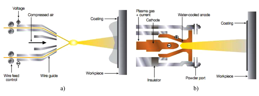
In the present experimental program, seven out of eight materials have been applied on friction shims by means of a thermal spray, while the remaining material, as above said, has been applied through electroless nickel plating. In general thermal spray is an industrial procedure to apply coatings by means of special devices/systems through which molten metals are propelled at high speed on cleaned and prepared surfaces. In this procedure, the coating material is melted by a heat source and then it is propelled by means of gases on a base material, where it solidifies forming a solid layer. In the present experimental program, all the specimens coated with thermal spray have been realized following one of two alternative techniques: arc wire or atmospheric plasma spray. In the next, a brief overview on the applied techniques is given (Figs. 2a and 2b).
2.2.1. AWS, Arc Wire Spray (“Soft Materials”)
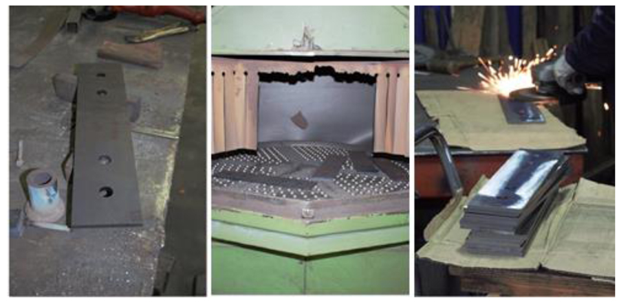
The electric arc wire process is based on the development of heat used to melt the coating feedstock. The electric arc wire spray process is in some way very similar to gas metal arc welding and uses two metallic wires, usually of the same composition, as the coating feedstock. The two wires are electrically charged with opposed polarities (+/-) and are fed into the arc gun at a precise, controlled speed. When the wires are brought together at the contact point, the opposing charges on the wires create an arc that continuously melts the tips of the wires. Compressed air is used to atomize the molten material in order to shot it on a properly prepared workpiece surface. Before coating the plates with the selected materials, some preliminary treatments were carried out. The first treatment (Fig. 3) has consisted in a mechanical blasting at low pressure with metal grit and corundum mesh. Then the plates have been grinded using an angle grinder with discs of zirconium oxide and corundum. Subsequently, before spraying the coatings, on all the plates an adhesion layer has been applied. During the spray application, in order to verify the correct application of the coating layers on each plate, a series of measurements with an electronic feeler gauge have been performed.
2.2.2. APS, Atmospheric Plasma Spray (“Hard Materials”)
The flexibility of the plasma spray process comes from its ability to develop easily the energy required to melt almost any coating material produced in the form of powder. The plasma gun uses a chamber with one or more cathodes (electrodes) and an anode (nozzle). With this process gases flowing through the chamber are ionized such that a plasma plume develops. Afterwards, the feedstock material is injected into the hot gas plume, where it is melted and propelled towards the target substrate to form the coating. The gases typically used are argon, hydrogen, nitrogen and helium, either individually or in mixtures of two or even three gases. The gas flows and the applied current can be accurately regulated. In addition, the shape and bare size of the nozzle, the point and angle that the material is injected into the plume, as well as the distance of the gun to the target surface are also controlled.
2.2.3. Electroless Nickel Plating (3M Gmbh)
Electroless nickel plating is a process for depositing a nickel alloy from aqueous solutions onto a substrate without the use of electric current. It differs, therefore, from electroplating which depends on an external source of direct current to reduce nickel ions in the electrolyte to nickel metal on the substrate. Electroless nickel plating is a chemical process which reduces nickel ions in solution by chemical reduction. In the case of the coating produced by 3M Gmbh diamond powder is added to the bath obtaining and high hardness friction material.
2.3. Test Layout and Main Results
The typical specimen tested within the current experimental activity is composed by a system of steel plates assembled in order to test the uni-axial behaviour of friction interfaces resulting from the coupling of a stainless steel plate with friction shims coated with one of the eight materials previously mentioned. The tested sub-assembly is inspired from the specimens’ layout provided for slip tests by EN1090-2 [22]. In particular, it is constituted by a slotted steel plate realized in 1.4301 Stainless Steel [30] equivalent to AISI 304 steel, a steel plate with normal holes used to connect the specimen to the testing machine and external steel plates and friction shims pre-stressed with M20 class 10.9 HV bolts [31] (Fig. 4a).
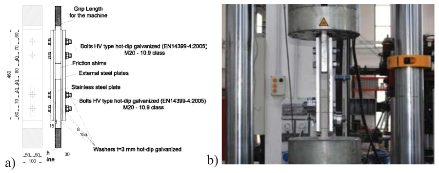
The tested specimen aims to simulate the same conditions that are expected in the friction damper of a symmetrical friction beam-to-column connection, similar to the typology described in Fig. (1). The stainless steel plate with slotted holes simulates the internal plate of the haunch, while the external steel plates simulate the stems of the angles used to fasten the friction damper to the face of the column (Fig. 1). The loading protocol is that suggested by EN 15129, with variable displacement amplitudes ranging from a minimum of 6.25 mm to a maximum of 25 mm. The maximum amplitude has been defined providing a realistic estimate of the displacement demand arising at the friction damper level in current applications. The cycles were executed at increasing values of the speed that where defined in order to remain in a quasi-static range and according to the capabilities of the available equipment. The cycles’ velocity varied from 1 mm/s for the first 10 cycles to 5 mm/s for the cycles at the maximum amplitude. In each test, both the upper and lower M20 high strength bolts have been tightened by means of a torque wrench, in order to reach the proof load equal to 0.7Aboltfub = 0.7x245x1000 = 171500 N which has been controlled before starting the tests by means of appropriate donut load cells installed in the connection under the nuts of the bolts used to pre-stress the friction interface. All the tests have been carried out employing a universal testing machine Schenck Hydropuls S56 (Fig. 4b). Such a machine is constituted by a hydraulic piston with loading capacity equal to +/- 630 kN, maximum stroke equal to +/- 125 mm and a self-balanced steel frame used to counteract the axial load. Different sensors have been used before and during the test to control continuously the bolt force, the slippage load, the tightening torque and the displacement. The axial displacements of the device have been read directly from the transducer of the testing machine and, in the same way, the slippage force has been controlled directly exploiting the load cell of the machine. Before the test, the tightening torque has been applied through an hand torque wrench and monitored by means of a torque sensor Futek TAT430 with maximum capacity equal to 680 Nm. At the same time, the pre-tension applied to the bolts has been monitored before and during the test by means of donut load cells Futek LTH500 with maximum capacity of 222 kN. In the following the main results obtained in the experimental work are summarized. A more extensive discussion of the tests results can be found in [24].
2.3.1. Behaviour of “Hard” Materials
A synthesis of the results of the tests on the interfaces coupling stainless steel with friction shims coated with the “hard” coatings M6, M7 and M8 are delivered in Fig. (5), where the hysteretic curves of one of the two identical tests performed on each material are reported. In case of M6 carbide coating, the cyclic response has been characterized by the development of an initial value of the slip force equal to about 350 kN, followed by a progressive degradation that, at the end of the test was of about the 20%.
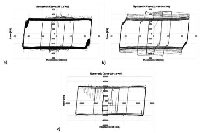
The hysteretic curve was affected by an initial stick-slip phase with the development of a first unstable cycle characterized by jumps of the force and sudden releases of energy. Nevertheless, after this first cycle, that probably allows to break the initial interatomic attraction between the surfaces in contact (adhesion component of friction), the slippage occurred regularly leading to a very stable response up to the end of the test. In case of M7 carbide coating, globally, a similar response was observed.
The behaviour, in this case, was characterized by an initial slip force equal to about 250 kN, that after few cycles slightly increased, stabilizing at a value of about 300 kN. Nevertheless in this case a stronger stick and slip behavior was observed and it was necessary to reduce the velocity to perform the test. Material M8, was characterized by a response that, as already observed in the past by the same authors with other materials such as brass or some types of phenolic rubbers [18], with two different phases. A first phase where the interface provided a strain hardening behaviour characterized by an increase of the slippage resistance of about 60% and a second phase characterized by a reduction of the slippage force which, at the end of the degradation returned to the initial value. In addition, in this case no stick and slip response was observed and all the cycles were characterized by a stable value of the slippage force. The initial value of the slippage force has been of about 400 kN. After the tests, the specimens have been opened in order to evaluate the damage of the interfaces, observing that, as expected, due to the higher hardness of the coating layer with respect to stainless steel, the greatest part of the damage was concentrated on the internal plate which at the end of the test had many scratches in the zone located underneath the bolt head. In Fig. (6), as an example, a diagram of the bolt forces and of the friction coefficient (obtained dividing the slip force by the bolt forces read continuously during the test through the annular load cells) represented versus the cumulative travel done by the damper are reported for the specimen with friction pads coated with M6 carbide is reported. From such a figure it is possible to observe that both bolts, which are initially tightened in order to reach the proof load equal to 171.5 kN, after the first cycle of the loading history lose about the 7% of the initial pre-load and afterwards they uniformly loosen during the test reaching at the end a total loss of about the 20%.

Clearly, this initial loss, that seems to occur just after the first sliding of the connection, should be properly accounted for in the design of the damper. From the comparison between Figs. (5a and 6) it is possible to note also that the degradation of the sliding force observed during the test is essentially due to the degradation of the bolts’ forces. In fact, they both degrade of about the 20% while the friction coefficient remains constant. Even though, for the sake of simplicity, detailed graphs representing the behavior of the bolts and the degradation of the friction coefficient for the other materials are not reported, analogous results have been obtained for all the other “hard” interfaces. Therefore, also for the other interfaces a correspondence between the bolts’ loosening and degradation of the sliding force has been observed.
2.3.2. Behaviour of “Soft” Materials
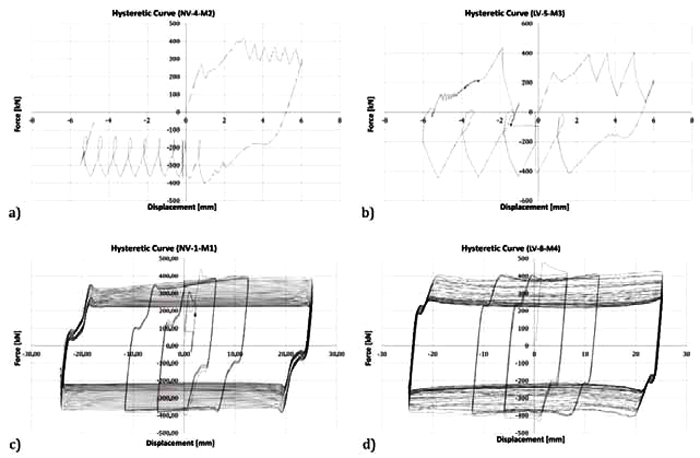
Similarly to what occurred in case of M7 carbide, also some of the soft materials exhibited a behaviour characterized by the stick-slip phenomenon. This is the case of three of the selected non-ferrous metal, namely M2, M3 and M5, whose response was characterized by alternate stops and starts of the motion with strong and sudden releases of energy (Figs. 7a and 7b).
Therefore, in all these cases the tests have been stopped prematurely in order to prevent damage to the testing equipment. For these materials, as reported in Figs. (7a and 7b), the initial slippage force was equal to about 200 kN and was followed by an increase of the slippage resistance up to about 400 kN which corresponds to a value of the friction coefficient equal to about 0.58. Obviously, their cyclic behaviour is not appropriate for seismic applications. Conversely, M1 and M4 metals have exhibited a very similar behaviour (Figs. 7c and 7d). In particular, their hysteretic response has been characterized by a value of the slippage force higher than the corresponding obtained with the “hard” materials but, on the other hand, they have also provided a more significant degradation due both to the bolt loosening and to the damage occurring in the friction pads. In Fig. (8) with green and blue lines are represented the results expressed in terms of friction coefficient and bolt forces versus the cumulated travel, for the two tests executed on the specimens with M4 friction pads. From this graphs, it is clear that, even though the actual value of the friction coefficient does not vary in the two tests, the bolts provide a significantly different behaviour leading, consequently, to a different response of the whole hysteretic response. In particular, in one of the two tests after the first sliding, a sudden loss of pre-tension in the bolts of about the 15% was observed leading, as a consequence, to a proportional loss of the sliding force. Such a different response of the specimens can be probably due to the imperfections of the coating applied on the friction shims, which in case of soft coatings is completely manual and leads to a non-uniform spread of the coating metal. In case of material M1, the degradation of the initial slippage force at the end of the tests was the 45%, while in case of material M4 it was about the 50%. Nevertheless, both materials provided very high values of the friction coefficient and, in particular, the initial friction coefficient of materials M1 and M4 were equal to about 0.55/0.65 and 0.7/0.9 respectively.

As in previous cases, also the specimens realized with soft materials were opened after the test, in order to evaluate the damage of the interfaces. As expected, in these cases the damage was mainly concentrated on the friction shims, while the stainless steel plates after the test were practically undamaged.
3. NUMERICAL INVESTIGATION
3.1. FE Modelling Assumptions
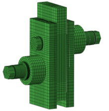
The Finite Element Models (FEMs) were developed using ABAQUS v.6.14 [32]. The geometries of the numerical models were nominally identical with those of the tested specimens (Fig. 9). The solid finite element type C3D8I (an 8-node linear brick, incompatible mode) was adopted for all steel plates and high strength bolts. The element choice was based on its capacity to avoid the shear-locking phenomenon that can significantly affect the initial stiffness of connection, unlike the C3D8R element.
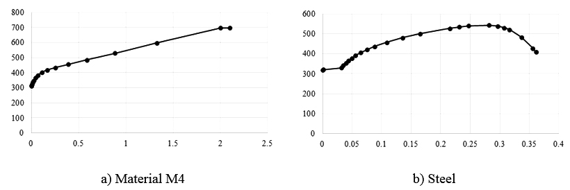
The steel properties of plates were modelled considering the nominal elastic properties, while the non-linear behaviour was modelled by means of the von Mises yield criteria. Plastic hardening was represented using a nonlinear kinematic and isotropic hardening. Metal plasticity was considered for the coating layer as well. The true stress-true strain curves adopted for material M4 and steel plates are given in Fig. (10).
The bolts were modelled by meshing a solid cylinder having the nominal circular gross area of the bolt and the true stress-true strain curves were derived from [33, 34].
All possible interactions (bolt head to outer plate, bolt shank to corresponding bolt hole, plates in contact) are modelled by means of “Surface to Surface contact” with the finite sliding formulation. Both tangential and normal behaviour are considered, the former using a “Penalty” friction formulation together with “slip-rate-dependent data” scaled for explicit analyses, while the latter using the “Hard-Contact” formulation. “Tie” constraints were used to model the bond between the M4 coating layer and the steel shim.
The bolt clamping was modelled using the “Bolt load” feature available in the FE software and the design preload value was imposed. The clamping was applied in an individual step prior to the application of the loading protocol.
The external restraints were simulated by slaving to Reference Points (RP) the nodes belonging to the end portion of the internal plate of the device. The displacement history was imposed on the RP located at one end of the device.
In order to reproduce the temperature variation and propagation due to heating induced by friction, the thermal properties were also taken into account. The Specific Heat c was set equal to 4.52E+8 mJ/ton/oC, the Thermal Expansion αL was assumed equal to 1.26E-5 mm/mm/ oC and the Thermal Conductivity k equal to 48 mW/mm/ oC.
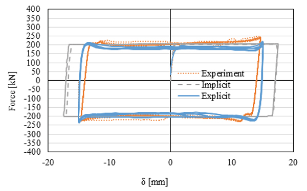
Both implicit quasi static and explicit dynamic analyses have been carried out in order to investigate the computational efficiency and accuracy of these types of analysis.
An example showing the difference between the types of analysis is shown in Fig. (11). It should be noted that both types of analysis are effective to simulate the overall behaviour of the friction connections. Generally, implicit analyses provide more reliable results than explicit ones. On the other hand, explicit analyses provide advantages in terms of computational efficiency. Table 1 summarizes the average computational time necessary to carry out each type of analysis. As it can be easily recognized, the implicit solver requires a heavier computational effort.
| FE Solver | Average Duration of Analysis | Comment on Results |
|---|---|---|
| Implicit | 24 hours | Both FE solvers are successful to demonstrate results analogous to experimental ones. |
| Explicit | 6 hours |
3.2. The Influence of Disk Springs on the Friction Response
Table 2 reports the types of specimens with the corresponding number of Disl Sprinfs (DS). The geometry of the fixed part was disregarded in order to decrease computational demand, as it has no influence on the results (Fig. 12).
| No. of DS | M6 | M4 |
|---|---|---|
| 9 DS | NV 21 | NV 17 |
| 6 DS | NV 22 | NV 18 |
| 3 DS | NV 23 | NV 19 |
| 0 DS | NV 24 | NV 20 |
The numerical results are discussed based on the following outputs:
- − Sliding Force [kN] - Displacement [mm] / Time [s].
- − Total Preload Magnitude [kN] - Displacement [mm].
- − Temperature [kN] - Displacement [mm] / Time [s].
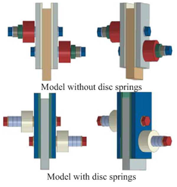
3.2.1. The Influence of Disk Springs in Lap Shear Joints with M6 Friction Material [NV-21-22-23-24]
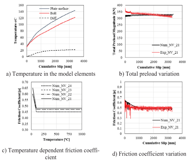
Calibrating the models for each experiment with a different number of springs is done in the way of manipulating preloading magnitude and friction coefficient so as to match sliding force-displacement curves of experiments. Fig. (13a) shows for model NV-21 that the temperature in the assembly elements (bolts and plates) increases with cumulative sliding. As expected, the energy dissipated by friction is converted to thermal energy. It was observed that after 3000mm of cumulative slip, the average temperature difference between plate surface and bolt is about 15 to 20oC for all models. Even though thermal properties are modelled as mentioned before, it seems that the preload forces have not been affected significantly and they remain constant in the models (Fig. 13b), mostly because the thermal expansion occurs in both the plates and bolts.
The partial loss of friction coefficient was modelled in the FE models using temperature-dependent friction laws calibrated based on experimental results (Fig. 13c). As temperature increases because of continuous sliding of plates, friction coefficient decreases accordingly, and as possible to observe in Fig. (13d), the model is able to predict this phenomenon.
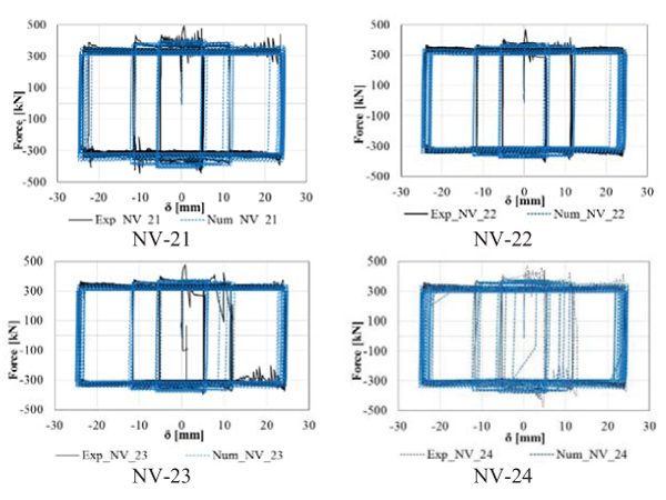
Fig. (14) shows the comparison between the experimental and numerical curves in terms of sliding force and displacement. As it can be observed, the FE model is capable of providing accurate results.
3.2.2. The Influence of Disk Springs in Lap Shear Joints with the M4 Material [NV-17-18-19-20]
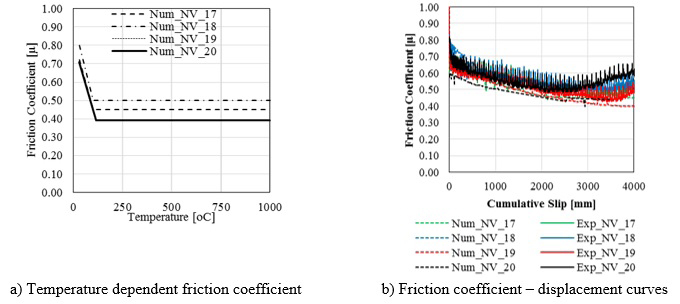
As observed during the experimental tests, the M4 material exhibits larger friction behavior degradation during the slip, resulting in a more difficult modelling. Also, in this case, no significant differences in terms of loss of preload were observed between the models with varying number of DS. As temperature increases because of continuous sliding of plates, friction coefficient decreases according to given temperature-dependent input data (Fig. 15a). Moreover, there is no direct relation in the number of disc springs and degradation of friction coefficients (Fig. 15b).
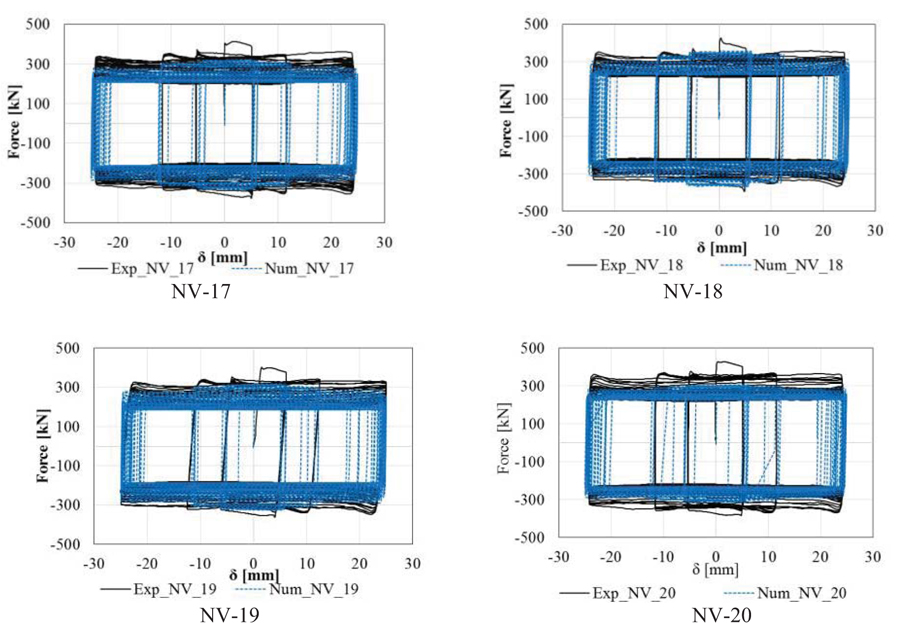
The sliding force-displacement curves are depicted in Fig. (16), where it can be recognized the distinct degradation of the slip capacity cycle by cycle.
CONCLUSION
The lap shear tests performed at the University of Salerno have been conducted in order to give insight into the friction behaviour of various materials considered as potential solutions for the friction damper. The results of the experimental campaign have been further used to calibrate FE models. Based on the two investigations, the following remarks can be drawn:
- The experimental campaign showed that both hard and soft metals can be used in combination with stainless steel obtaining satisfactory performance under cyclic loads. Nevertheless soft material, due to higher wearing, are more prone to degradation;
- The variability of the bolt forces during sliding is significant and their effect needs to be accounted for in design and analyses;
- The presence or the number of disc springs does not significantly influence the response in terms of bolt preload loss;
- At high slip velocities, large temperatures are developed within the specimen. When modelling temperature-dependent friction coefficients calibrated on experimental results, the good agreement can be obtained by the FE models. Modelling this effect is crucial as it causes a reduction in the slip force capacity. This is due to the transverse dilatation that initially increases the pressure, while bolt tightening reduce due to elongation of the shank;
- The FE model that accounts for both degradation of bolt preload and friction coefficient is able to replicate the experimental test with a good level of precision.
DISCLOSURE
Part of this article has been previously published in Experimental behavior of innovative thermal spray coating materials for FREEDAM joints. Composites Part B: Engineering Volume 115, 15 April 2017, Pages 289-299.
CONSENT FOR PUBLICATION
Not applicable.
CONFLICT OF INTEREST
The authors declare no conflict of interest, financial or otherwise.
ACKNOWLEDGEMENTS
The research activity herein presented has been supported by the European Community by research grant RFSR-CT-2015-00022. The support of the European Commission within RFCS Research & Innovation is gratefully acknowledged.


