All published articles of this journal are available on ScienceDirect.
Progressive Collapse Assessment of the Steel Moment-frame with Composite Floor Slabs Based on Membrane Action and Energy Equilibrium
Abstract
Background and Objective:
Progressive collapse resistance of the steel moment-frame with composite floor slabs can be assessed by sudden column loss scenarios. In order to investigate the progressive collapse-resistant capacity of the steel moment-frame with composite floor slabs, a simplified approach based on the theory of membrane action and energy equilibrium principle is presented, which assessed the behaviour of progressive collapse resistance of this frame subjected to the removal of a penultimate column via the static and dynamic analysis.
Mateial and Method:
The residual vertical bearing capacity model considering of the membrane action and tie force (TF) method of composite floor slabs is developed to evaluate the force mechanism of the composite floor slabs. An energy-based theoretical framework is proposed for calculating the maximum allowable dynamic demands based on the nonlinear static Pulldown analysis, which is used to explore the relationship between of dynamic and static response in the progressive collapse process. Furthermore, the finite element software SAP2000 is used to calculate the numerical example to verify the reliability of this simplified approach.
Results:
The results show that the composite floor slabs significantly improve the structural progressive collapse-resistant ability and this simplified approach evaluates the progressive collapse resistance of the whole structure effectively.
Conclusion:
The existence of the floor can increase the ductility of the structure, and increase the progressive collapse-resistant ability. The appropriate value of the DIF depends on the ductility and amount of inelastic action the structure would experience during the column removal scenario.
1. INTRODUCTION
The progressive collapse of the structure may be described as the spread of an initial local structural damages or failure from element to element due to terrorism attacks, gas explosion, earthquake, fire and other emergencies, which in turn lead to the changing of internal force in adjacent structures, prompting more elements failure caused by progressive expansion, eventually resulting in the collapse of an entire structure or disproportionately large part of it [1]. It is a complex subject to evaluate the progressive collapse-resistant capacity of structures under different progressive collapse conditions. The alternative path method (APM) is most widely used to analyze the building structures subject to postulate scenarios of initial local structural damages and the load-displacement curves are used to evaluate the progressive collapse-resistant behavior of structures under progressive collapse conditions [2, 3]. Izzudin et al. [4] and Vlassis et al. [5] proposed a framework for a simplified progressive collapse-resistant evaluation of multi-storey buildings, which is evaluated from three aspects: static response, dynamic response and ductility performance. Dat et al. [6] mainly investigated the beam mechanism in direct affecting area of the structures based on the single degree of freedom model through the principle of energy equilibrium principle. Kim et al. [7, 8] carried out the evaluation of the ultimate bearing capacity and the performance of the structure combined with Pushdown analysis method. Yi Weijian et al. [9] and Li Yi et al. [10] investigated the collapse-resistant mechanism of RC frame combined with Pushdown analysis method. Huang Zhiwei, et al. [11] conducted the reliability assessment of progressive collapse-resisting capacity of reinforced concrete frame under static load. Ding Yang et al. [12] proposed a rapid assessment method by introducing the substructure model based on the alternative path method(APM). P. Foraboschi [13, 14] designed and constructed a test building to investigate the progressive collapse assessment of steel moment-frames with composite floor slabs, which took full advantage of the properties, capabilities and opportunities afforded by steel.
Existing experimental and numerical investigations have demonstrated that the evaluation of structure progressive collapse is mainly focused on three key areas:
- Evaluation has mainly focused on the static progressive collapse-resistant capacity of the frame structures following the current representative design guidelines and new simplified approach has been proposed to facilitate the designers based on the existing methods.
- Research has mainly focused on the pure frame and the progressive collapse resistant demand of the RC frames under the beam mechanism (i.e., for small deformations), and that for the catenary mechanism is lacking;
- The nonlinear and dynamic effects at large deformations are not well considered in current research, and the effects of membrane action of floor slabs on structural progressive collapse-resistant capacity are not considered from the perspective of structural integrity.
The composite floor slabs as planar components have a bidirectional beneficial tension effect on the frame structures [15], which could enhance the ability of progressive collapse-resistant capacity of the structure through the tensile membrane action at the large deformations [16]. Although the recommended tie force(TF) method takes into account the catenary mechanism to describe the progressive collapse demand [3], it neglects the contributions of the membrane action of composite floor slabs at large deformations, which leads to the APM over-conservative and lack of sufficient theory and test data supporting. Nonlinear incremental dynamic analysis also known as the “nonlinear dynamic Pushdown analysis” [17], is usually a promising method for estimating the progressive collapse-resistant capacity, which is time-consuming and requires repeated computational calculations to evaluate the structural progressive collapse-resistant dynamic performance. As a consequence, a more convenient and engineer-friendly methods should be adopted to evaluate the progressive collapse-resistant capacity of the structure, and appropriate measures can be taken to enhance the structural collapse-resistant performance.
In this paper, a simplified approach based on the theory of membrane action and energy equilibrium principle is presented, which assessed the behaviour of progressive collapse resistance of this frame subjected to the removal of a penultimate column via the static and dynamic analysis. This approach requires three dimensional(3D) analysis of the floor framing considering geometric and material nonlinearity, which focuses on redundancy and enhancement of the alternate load path method(AMP) [2]. Also, the dynamic impact factor(DIF), which is widely used to account for dynamic effects within a static design framework is investigated. The residual vertical bearing capacity model considering of the membrane action and tie force(TF) method of composite floor slabs is developed to evaluate the force mechanism and deformation model of the beam-slab collapse-resistant system in direct affecting area. An energy-based theoretical framework is proposed for calculating the maximum allowable dynamic demands based on the nonlinear static Pulldown analysis. Furthermore, the finite element software SAP2000 is used to calculate the numerical example to verify the applicability and reliability of this simplified approach and the relationship curve between the residual bearing capacity and the ultimate displacement is obtained. The analytical results show that the composite floor slabs can effectively enhance the ability to resist progressive collapse via improving the integrity of the structure. The simplified approach is reliable, and it moves the evaluation of the progressive collapse resistance from the generalities to the quantifiable, with all benefits that this brings for understanding and design.
2. ANALYSIS MODEL OF STRUCTURAL PROGRESSIVE COLLAPSE
In the case of sudden loss of the vertical key load-bearing members, axial unbalance load of the removed column will quickly seek a new load path to redistribute in a few milliseconds [18]. As a result, the consequent structural response is dynamic, generally characterized by significant geometrical and material nonlinearities. There are three simultaneous changes which may increase the internal forces in direct affecting area of the structures:
- Spans of slabs and beams in direct affecting area bridging over the removed key load-bearing components will be two times the initial ones, and all floors above the first floor will deflect identically and dynamically under uniform gravity loads to seek a new equilibrium path.
- Existing gravity loads are amplified by a dynamic factor is up to 2.0 [19].
- Spans of slabs and beams in indirect affecting area can be considered that the interaction between the layers to change its force little effect, for the form of the basic load did not change, as shown in Fig. (1).
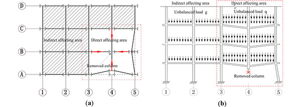
There are two types of connection between the primary girders and secondary beams,which are hinged connection and fully restrained connection. Usually, the secondary beams are determined as simply supported beams, the primary girder-secondary beam connection only transfer beam vertical bearing reaction force without bending moment, the connection is hinged connection. However, steel frame beam-to-column connection is the moment connection. In this paper, in order to investigate the capacity of progressive collapse resistance of the steel moment-frame with composite floor slabs, the beneficial effect of secondary beams is neglected, and the model of the steel moment-frame with composite floor slabs is established, as shown in Fig. (1).
When a multi-storey building is subjected to sudden column loss, the frame structure can prevent the progressive collapse mainly by two progressive collapse-resistant mechanisms, i.e. beam mechanism at small deformations and the catenary mechanism at large deformations. Initially, the low-load-level system acts as a pure bending element, and with the increase of load and rotation, the system will transition from the bending element to the catenary element. In a two dimensional catenary system, the integrity of the system depends on the capacity of the support to resist the horizontal component of the force. Typically, columns are not designed to receive lateral loads of the magnitude required for the balance of a catenary system, as shown in Fig. (1b). In the penultimate column loss case, a beam-slab substructure is similar to a simply supported slab in the sense that both are laterally-unrestrained, as shown in Fig. (2). The advantage of a 3D behavior is that the balance forces are internal to the system. In principle, the floor system undergoes a deformation that reshapes the floor plate into an inverted dome or a dish, (see Fig. 2b). Therefore, the equilibrium of the system does not depend on the capacity of the catenary tie forces at the support. The radial tensile forces created as a result of the dishing action is balanced with compressive hoop stresses of the composite floor system [20].
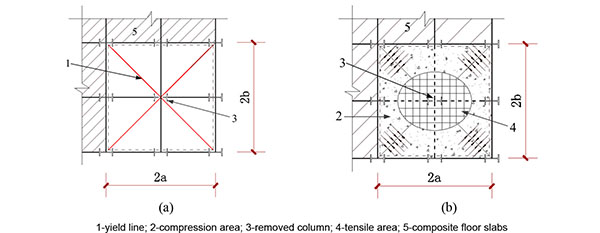
Compared to a simply-supported slab, a beam-slab substructure requires additional factors to be considered. At small vertical displacements, the yield-line configuration of a beam-slab substructure bridging over the column loss is depicted in Fig. (2a). The plastic limit capacity of the beam-slab substructure does not reach the peak load, and composite floor slabs could support loads considerably greater than those calculated by the well-established yield-line approach [21]. At very large displacements, in line with the floor cracking yield gradually disappear. The affected slabs, which become laterally unrestrained with two consecutive edges discontinuous, are capable of forming a peripheral compressive area to support the tensile membrane forces in the central deflected region [18]. Membrane action in a laterally unrestrained slab can be explained by Fig. (2b). The overall progressive collapse-resistant capacity of the beam-slab substructure therefore comprises tensile membrane force in the center of the slab and catenary tie forces in steel beams.
3. PROGRESSIVE COLLAPSE RESISTANCE OF STEEL MOMENT-FRAME WITH COMPOSITE FLOOR SLABS
3.1. Ultimate Load Resistance of Beam-slab Substructure
When the structures undergoing large deformations, composite floor slabs exhibit a bidirectional oriented tensile membrane action in which the load transfers in each direction is equivalent to a catenary mechanism. The catenary mechanism is the prototype model of the TF method adopted in the design codes, by which the axial tensile force demand of beams in one direction and floor slabs in two directions is calculated [22].
The tensile membrane action of a beam-slab substructure bridging over removed column is given in Fig. (2b). Based on the failure criterion, the ultimate progressive collapse-resistant capacity of steel moment-frame with composite floor slabs is established as Eq. (1):
| Pu=Pslab+Pbeam | (1) |
3.1.1. Ultimate Tensile Capacity Pbeam of Double-span Beams
The deformation of the steel beams is controlled by the vertical displacement of the failure column, and the B3-B5 beam is analyzed as shown in Fig. (3).

Applying vertical force equilibrium principle, the following expression can be written as Eq. (2):
 |
(2) |
Assuming the overall dimensions in different directions is, L1=L2=L and the double-span beams are continuous through beam-column joints. Therefore, the ultimate axial tensile force of steel beams satisfies T1=T2=T. For convenience of calculation, an ideal elastic-perfectly plastic stress-strain relationship was applied in the process of theoretical calculation, and the deformation of steel beams was measured by introducing the stain ε, which can be computed as follows:
 |
(3) |
| T=EεsAs, when ε < εy | (4a) |
| T=fs,yAs, when ε ≥ εy | (4b) |
Where εy is the tensile yield stain of steel beams, E is the elastic modulus of steel beams, fs,y is the yield strength of steel, and As is the cross-sectional area of steel beams.
The ultimate axial tensile capacity of double-span beams are given as Eq. (5):
 |
(5) |
3.1.2. Ultimate Tensile Capacity Pslab of Double-span Composite Floor Slabs
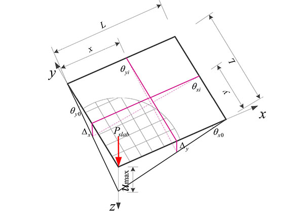
The composite floor slab components, including the profiled sheet, steel reinforcement and concrete slab, are attached together and deform in a compatible manner. Once the composite floor slab reaches its yield membrane force at large deformations, the concrete cracking, it deforms in a ductile, perfectly plastic manner up till failure. It is considered that the peripheral compressive area will reduce the demand of tensile membrane forces on the perimeter columns and thus enable the structure to sustain the amplified axial unbalanced compressive forces in columns above the removed column longer before the onset of progressive collapse [18]. Due to symmetry considerations, only 1/4 of the floor system in direct affecting area of the structure is considered in the analysis with the appropriate boundary conditions along the axes of symmetry, as shown in Fig. (4).
| Pslab=Tdeck+Tmesh | (6) |
The tensile strength of the slab has been included in the catenary action, in order to mobilise all available strength. The ultimate tensile capacity Pslab of double-span composite floor slabs is given as Eq. (6), where Tdeck is the strength of the profiled sheet and Tmesh is the strength of the mesh reinforcement embedded in the slab.
The resistance Tmesh of the distributed wires is controlled by the tensile yield stress. Tmesh,x, Tmesh,y is the tensile forces of the welded wires in unit width in x-direction and y-direction. In this paper, assuming the same two-way distribution network is arranged in the composite floor slabs, and an ideal elastic-perfectly plastic stress-strain relationship was applied. Therefore, the ultimate tensile axial forces of the welded wires in unit width in x-direction and y-direction satisfy Tmesh,x=Tmesh,y.
Under the action of a concentrated load, the deformation of the welded wires is assumed to be a linear deformation. According to the deformation compatibility, the average strain of the mesh is calculated:
 |
(7) |
Tension forces of mesh tension can be obtained according to the strain:
 |
(8a) |
 |
(8b) |
Where εm,y is the tensile yield strain of the wire, Es is the elastic modulus of the wire, and fm,y is the tensile yield stress of the wire.
The failure of profiled sheet subjected to tension occurs because of insufficient end distance, box shear failure or bearing failure. Nie et al. carried out thirteen tests of composite beams in three groups, and the test showed that the actual shear strength of the shear studs in the composite beam was much larger than the calculated value. Based on ensured quality of the stud, the phenomenon of self-destruction rarely occurs between the composite floor slabs and steel beams even for full shear connection and partial shear connection [23]. Because of these provisions, the critical failure mode is in bearing failure. Hence, the maximum tying force carried by profiled sheet was calculated:
| Tdeck=Ndtpb | (9) |
Where N is the number of shear studs used to connect an edge of profiled sheet on beam normal to sag per meter, d is the diameter of shear studs, t is the thickness of profiled sheet, and pb is the bearing strength of profiled sheet.
Assuming that the rib direction of the profiled sheet is in the y-direction, then the tension membrane force per unit width in the y-direction parallel to rib can be written as follows:
| Pslab,y=φTmesh,y+φTdeck | (10) |
The tension membrane force per unit width perpendicular to the rib can be written from Eq. (11):
| Pslab,x=φTmesh,x | (11) |
Assuming the weld wires and profiled sheet to fail simultaneously is rather conservative, so introduced is the effective area reduction factor φ=0.5.
According to the Fig. (4), the total tensile capacity of the composite floor slabs is computed by integrating the vertical component of the membrane force in the floor slab along the periphery of the floor.
 |
(12) |
The total angle of rotation of the slab at xi, yi in the x-direction and y-direction can be expressed in terms of the vertical deflection as follows see Fig. (4):
 |
(13a) |
 |
(13b) |
The beam chord rotation is thus,
 |
(14) |
The capacity of the beam-slab substructure at displacement μmax should be modified as Eq. (15).
 |
(15) |
As  can be obtained through the deformation compatibility according to the deflection μmax, the integral equation only contains one unknown parameter. Therefore the vertical ultimate static bearing capacity at the joint above the failure column considering the membrane action of the composite floor slabs and the catenary action of the double-span steel beams is calculated according to the limit displacement μmax. The overall ultimate bearing capacity of the multi-storey building can be conservatively calculated by
  .
.
3.2. Energy-based Progressive Collapse Dynamic Analysis
Nonlinear dynamic demand is a more realistic representation of the progressive collapse-resistant demand, which can be calculated using dynamic equilibrium equations or energy conservation equations. However, in order to solve dynamic equilibrium equations, nonlinear dynamic finite element analysis is usually performed, which is time-consuming [22]. Therefore, dynamic analysis is commonly used for buildings with high security risks. In order to achieve this, a theoretical framework based on energy equilibrium is presented for the simplified calculation and analysis of progressive collapse-resistant design in engineering.
Beams and slabs of the building are usually designed with the same load, strength, rigidity in each layer. Spans of beam-slab substructure in direct affecting area produce the single bending deformation form shown in Fig. (5) under unbalanced load. Ignoring the distribution of mass along the beam length, the uniformly distributed load and distributed mass of the beam are concentrated at the upper node of the removed column, and the whole structure is similar to a generalized single-degree-of-freedom (SDOF) system [24]. In these approaches, the applied model is widely employed to represent the mechanical properties, including collapse resistance and deformation, of the collapse-resisting substructures, as shown in Fig. (5). It should be pointed out that the resistance of the SDOF model refers to as the collapse-resistant capacity of the overall structure.
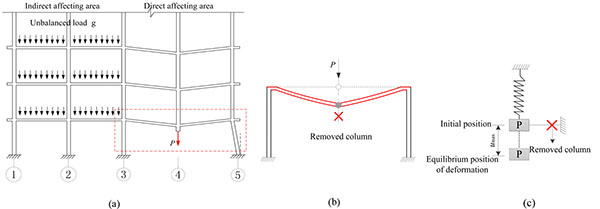
According to the Pulldown progressive collapse analysis method proposed by Liu et al. [25], a single downward concentrated load P is applied at the upper node of the removed column, while the gravity load within the indirect affecting area is contained original instead of being amplified. According to the principle of energy equilibrium, the energy equilibrium principle of deformation mechanics indicates that the work of external force is equal to the increment of kinetic energy, damping dissipation energy, and strain energy of the structural components, which can be written from Eq. (16).
| EK+ED+EA=WE | (16) |
The basic concept is energy equilibrium, i.e., the structure must absorb the potential energy generated due to the removed column. When a multi-storey building is subjected to sudden column loss, the system has the maximum potential energy. Since the force in the spring is zero at this time, the system is falling down due to the weight of the system. At the final equilibrium position, the falling system has zero velocity and all the potential energy is absorbed by the spring. Energy dissipated in the structure due to damping is minimum compared with the energy absorbed due to plastic deformation. Therefore, damping is not considered in the following description of the progressive collapse procedure [26].
According to the correct formula for the transformation from external work into internal energy, the problem can be treated as static one, and the external work  W done by the unbalanced load should be equal to the increment of strain energy
  E absorbed by the double-span beam-slab substructure system above the missing column. If
  E >
E >  W, the system is in a stable equilibrium state and will not collapse. If
  E <
E <  W, the system is in the unstable equilibrium state and will collapse. The energy equilibrium relation of the transition from stable equilibrium to unstable equilibrium can be simplified as:
 |
(17) |
Where  represents the strain energy of the double-span beam-slab substructure system in direct affecting area, R(u,u) represents the vertical resistance of the double-span beam-slab substructure in direct affecting area;
  represents the external work done by the unbalanced load, P is the the unbalanced load, umax is the maximum vertical deflection.
Through the above analysis, the paper comes to the conclusion that the work made by static and dynamic loads is only related to the starting point and ending point, and the strain energy of the structure is the same in the same deformation mode. When the peak displacement ui is obtained, the external work done by the external force can be expressed as follows:
 |
(18) |
In the same displacement state, the external work made by the equivalent dynamic load can be expressed:
 |
(19) |
With the availability of the nonlinear static vertical load-displacement response, the relationship between of dynamic and static resistance requirements of the beam-slab collapse-resistant system based on energy equilibrium principle is obtained. In this manner, the dynamic enhancement associated with sudden column loss can be included using only the results from a nonlinear static Pulldown analysis, as shown in Eq. (20).
 |
(20) |
Where Ps=Ps(ui) represents the static capacity required to produce the vertical displacement ui at the upper node of the removed column. The function Pd=Pd(ui) represents the progressive collapse-resistant capacity curve, i.e., the equivalent dynamic bearing capacity of the structure considering the dynamic effect required to produce the vertical displacement ui at the upper node of the removed column.
This approach with nonlinear static analysis can accurately predict the bearing capacity of the structure. Compared with direct nonlinear dynamic Pulldown analysis, the equivalent dynamic response analysis method based on energy conservation principle is simplified and effective as it greatly reduces the computational amount, which only needs to carry out a calculation on the basis of nonlinear analysis.
4. APPLICATION EXAMPLE
4.1. The General Engineering Situation and Finite Element Modeling
The verification is based on two 4×3 bay of 5-storey steel moment-frames and two steel moment-frame substructures, which are designed in accordance with the current code for design of steel structures(GB50017-2003) [27]. The H-shaped doubled-span beams of HW300mm×300mm×10mm×16mm (section depth × flange width × web thickness × flange thickness), and H-shaped columns of HM500mm×300mm×10mm×16mm are used for numerical analysis. The column height is 4.2m, and columns are spaced at 6m. All columns and beams are made of Q345 steel with yield strength of 310 MPa. The composite floor slabs system in Fig. (1) consists of a 28mm deep profiled sheet with an 80mm concrete (weight=25kN/m3) topping with nominal compressive strength of 14.3 MPa. The profiled sheet (YX28-150-900I) is 1.2mm thick with yield strength of 300 MPa, and an average rib width of 150mm. The concrete slab is reinforced using a welded wire mesh 200mm by 200mm grid spacing, HPB300 steel, with yield stress of 270MPa. The shear connector studs with a diameter of 16mm are utilized to develop composite action between the beams and the composite floor slabs. An elastic modulus (E) of 2.06×10⁵ MPa is utilized for both the weld wire mesh and the profiled sheet. Fully welded connections are utilized to connect the steel beams to the columns via fillet weld and groove weld.
A material and geometric nonlinear finite element analysis was conducted for pure steel moment-frame and steel moment-frame with composite floor slabs by using the finite element software SAP2000 program. The model is assumed to be fixed on the ground and large displacement analysis is used to engage the membrane action in composite floor slabs and catenary action in steel beams. The beam element was used to simulate steel beams and columns, which have a bilinear elastic plastic hardening stress-strain relationship. The analysis model is established by using the dynamic plastic link element in the SAP2000 program, and the ideal elastic and plastic restoring force model is taken. Plastic moment hinges (P-M) are assigned to beam ends, and plastic moment hinges (P-M-M) are assigned to column ends in this paper, where the axial force and bending moment are simultaneously taken into account. The mechanical properties of moment hinge at the member end of doubled-span beams is taken from FEMA 356 (FEMA, 2000) [28], as shown in Fig. (6).
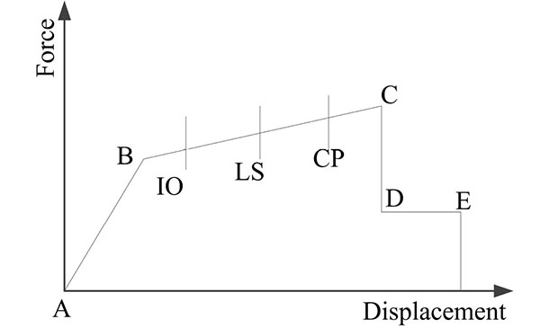
For pure steel frame model, according to the principle of equal bending moment at beam ends and the tributary area, self-weight of the slab and all the dead loads and live load on it are distributed to the beam elements for each floor. A downward loading combination Load=DL+0.25 LL [1] recommended by the GSA guidelines is adopted for the linear static analysis, where DL includes the structural weight and additional dead loads, LL includes the live load.
In order to effectively simulate the mechanical properties of composite floor slabs, stiffness of profiled sheet in the orthogonal direction is negligible and can be ignored according to the arrangement form of composite floor slabs. A simplified equivalent composite slab model is therefore proposed to avoid complicated geometry modeling of composite floor slabs and to reduce the computational time required for analysing 3D large scale framework [29]. When the profiled sheet end anchorage is sufficiently strong, an equivalent tie action can be derived by converting the profiled sheet into wires in longitudinal direction based on an equivalent area and second moment of area of the respective web and flange plates of the profiled sheet. The composite floor slabs shall be equivalent to uniform reinforced concrete section using the proposed simplified model with uniform thickness, Ds-Dp/2, and thus the equivalent concrete section could be modelled using a multi-storey shell element model and the wire is defined using rebar definition through SAP2000 library. The proposed simplified model for composite slab is shown in Fig. (7). Profiled sheet strip areas A1, A2 and A3 are calculated by multiplying the deck thickness by its strip length. Then equivalent area of rebar, ai for each profiled sheet strip area, Ai is computed by equating their second moment of area. The rebar area becomes, a1=A1, a2=A2 and  .
.
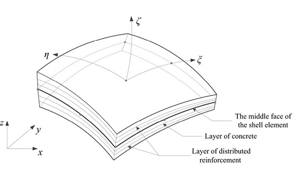
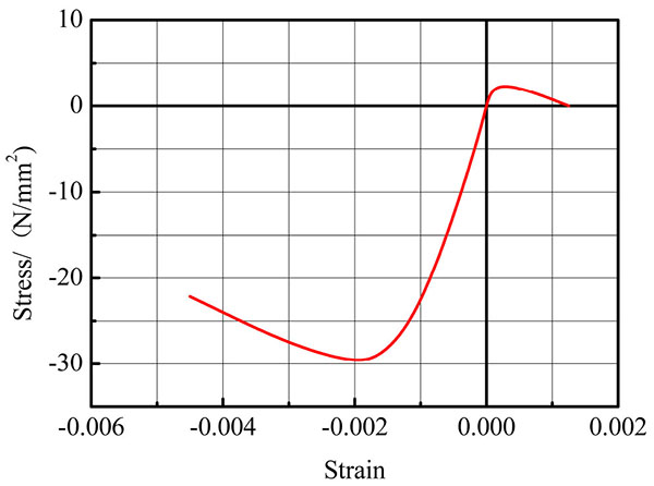
So by the above description, the composite floor slabs are equivalent to reinforced concrete slabs based on an equivalent area and second moment of area of the respective web and flange plates of the profiled sheet. For an accurate prediction of the complex stress-stain relationship of composite floor slabs, a general anisotropic multi-storey shell element model considering the in-plane bending, in-plane shear, and out-of-plane bending coupling action between the layered shell element was employed to simulate the composite floor slabs. The shell element is divided into several concrete layers and steel layers along the thickness direction, as shown in Fig. (8). In order to simulate the beam-plate full shear connection, the shear studs connecting the beam top flanges to the concrete slab through the profiled sheet were modeled using the common node between shell element and beam element. For concrete, the material constitutive relation is shown in Fig. (9). The welded wire mesh in the slab was modeled using truss elements, which have a uniaxial bilinear stress-strain relationship, and were assumed to be fully bonded to the concrete slab. Besides, the developed models have an assumption that strain rate effect on material response is not considered in the model, which justifies rather low. The simplified slab model is proposed based on the assumptions that slip between the concrete and metal deck is neglected.

4.2. Progressive Collapse Resistance
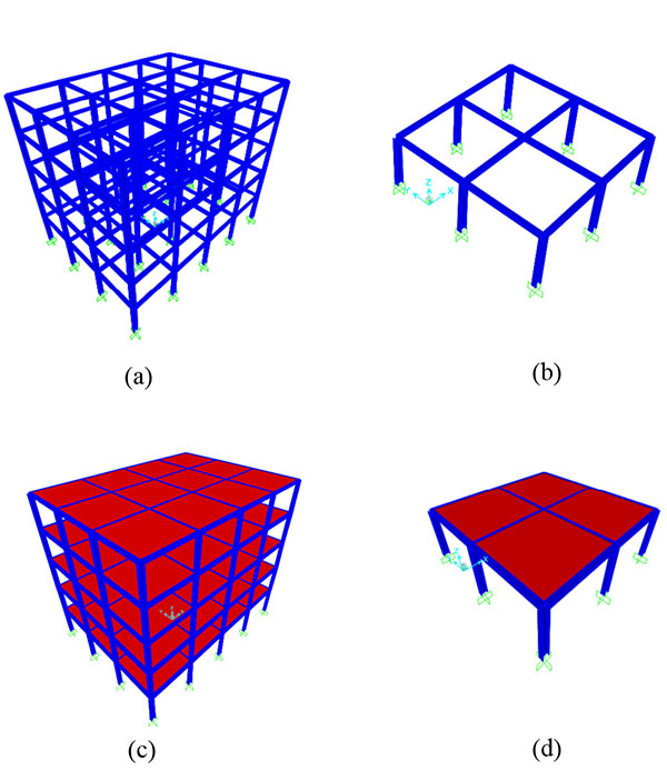
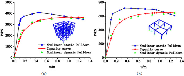
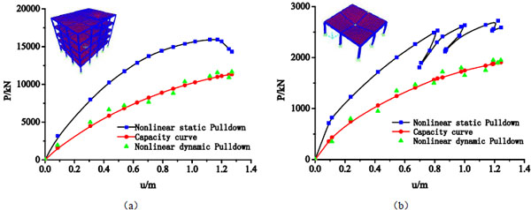
Simulations are conducted for the notional removel of a penultimate column for the dashed area in Fig. (1) to investigate the progressive collapse resistance of the steel moment-frame with composite floor slabs. This is intended to represent a situation in which a center column is lost to blast or impact. The progressive collapse-resistant capacity, which is defined as the ultimate downward loading capacity of the column-removing building, is further estimated using the nonlinear static Pulldown analysis and the nonlinear dynamic Pulldown analysis method. Considering both geometry and material nonlinearity, four models: (a) multi-storey spatial pure frame system; (b) single-layer spatial pure frame system; (c) multi-storey spatial frame system with composite floor slabs; (d) single-layer spatial frame system with composite floor slabs, were established, as shown in Fig. (10).
Displacement controlled approach was utilized to investigate progressive collapse-resistant capacity of the column-removed building. In every case, the computed vertical reaction at the column bases is reported as the load carried by the system. The position and quantity of the plastic hinge of the residual frame were analyzed, and the load-displacement response of those four column-removed conditions at the joint of the loss column was obtained as shown in Figs. (11 and 12).
4.2.1. Framing Only
Fig. (11) shows load-displacement results for multi-storey spatial pure frame system Fig. (11a) and single-layer spatial pure frame system (Fig. 11b) under column loss condition. This simulation includes only the columns, beams, and their connections. While the strength of multi-storey spatial pure frame system appears to be starkly different from that of single-layer spatial pure frame system, i.e., the strength of multi-storey spatial steel pure frame system is 4085.49kN versus 717.55kN for single-layer spatial pure frame system. From the ductility perspective, the multi-storey spatial pure frame system is significantly more ductile than the single-layer spatial pure frame system. In particular, the multi-storey spatial pure frame system reaches its peak load at 0.45m and its strength enjoys a gradual reduction in system strength afterward, while in contrast, single-layers spatial pure frame system reaches its peak load at 0.347m, and degrades thereafter. The ultimate static bearing capacity of single-layer spatial pure frame and multi-storey spatial pure frame system is 830.98kN and 5492.50kN respectively, according to the Eq. (5). The theoretical calculation results are slightly different from numerical results, due to the theoretical calculation based on some assumptions and simplifications, which the failure of the beam-to-column connections is not considered, as shown in Table 1.
| Analysis Method | Nonlinear Static Pulldown Analysis/kN | Equivalent Dynamic Bearing Capacity/kN | Direct Nonlinear Dynamic Pulldown Analysis/kN | Theoretical Calculation/kN |
|---|---|---|---|---|
| Model A | 4085.49 | 3638.39 | 3555.66 | 5492.50 |
| Model B | 717.55 | 650.76 | 642.86 | 830.98 |
| Model C | 15943 | 11339.10 | 11680 | 14381.36 |
| Model D | 2635 | 1906.53 | 1950.57 | 2500 |
Theoretical analysis and numerical calculation results indicate that: the ultimate bearing capacity of multi-storey spatial pure frame system is larger than single-layer spatial pure frame system. By improving capacity of failure joints via membrane action, the composite floor slabs effectively improve the integrity of the structure, while the progressive collapse-resistant capacity of the frame structure is enhanced and the development of the plastic hinge is delayed. It is overestimated to measure the ultimate progressive collapse-resistant capacity simply by the vertical displacement umax of the beam-to-column connection above the loss column, and the ductility of the joints should also be taken into account.
4.2.2. Steel Moment-frame with Composite Floor Slabs
Fig. (12) details the failure process observed in the simulations. In both cases, the beam-to-column connections above the loss column fail first. Fig. (12a) shows the load versus deflection response of the multi-storey spatial frame system with composite floor slabs (model C), while Fig. (12b) shows the load versus deflection response of single-layer spatial frame system with composite floor slabs (model D). For model C and model D, when the displacement of the beam-to-column connections above the loss column reaches 1.17m and 1.01m, the ultimate bearing capacity of the residual structure is 15943kN and 2635kN respectively, which are all larger than those of the pure frame system (model A and B). According to the Eq. (15), the static ultimate bearing capacity is 14381.36kN and 2500kN respectively, as shown in Table 1. The results show that the maximum error of theoretical analysis and numerical calculation are 9.8% and 5.1% respectively, which are less than 10%. It reveals that the analytic results of calculating in the theory and numerical simulation can be believed.
By the contrastive study, no more loads can be transferred to the system and the system appears to fail abruptly, when these connections fail in the pure frame case (see Fig. 11). The steel moment-frame with composite floor slabs (see Fig. 12) is able to absorb loss of these connections and keep carrying significant loads beyond, which is the primary reason for the disparity in ductility between pure frame and steel moment-frame with composite floor slabs simulation cases. In spite of the failure of all major connections, the system is able to keep carrying increasing load until the profiled sheet and the welded wires start to widespread rupture around the loss column area at a peak load. The results show that the integral performance can improve the progressive collapse-resistant ability of the structure. By improving capacity of failure joints via membrane action, the composite floor slabs effectively improve the integrity of the structure, while the progressive collapse-resistant capacity of the frame structure is enhanced and the development of the plastic hinge is delayed. The progressive collapse-resistant performance would be underestimated if the integral behavior of the structure were not taken into account.
4.3. Dynamic Resistance
It should be noted that progressive collapse is a dynamic event. Thus, it is necessary to evaluate the 3D and composite floor slab effects on the dynamic resistance of the steel moment-frame. Based on the nonlinear static Pulldown analysis, the dynamic response of the structure is deduced based on the theory of energy equilibrium principle according to Eq. (20), and the progressive collapse-resistant capacity curve for sudden column loss is obtained, as shown in Figs. (11 and 12).
According to the progressive collapse-resistant capacity curve, for different models, the ultimate dynamic bearing capacity is 3638.39KN, 650.76KN and 11339.10kN, 1906.53kN respectively, while the maximum dynamic bearing capacity is 3555.66kN, 642.86kN and 11680kN, 1950.57kN by repeating the direct nonlinear dynamic Pulldown operation several times until the convergence results are obtained. Fairly good agreement is observed between the results for sudden column loss using direct dynamic analysis (direct nonlinear dynamic Pulldown analysis) and energy-based approximate analysis (progressive collapse-resistant capacity curve), with differences in the load intensity being generally less than 5%. The results show that good agreement between the direct dynamic Pulldown analysis and approximate energy-based analysis results for pure frame and steel moment-frame with composite floor slabs, confirming that the approximate energy-based analysis procedure can accurately determine the real response of the structure. Compared with the direct nonlinear dynamic Pulldown analysis, this approach with nonlinear static analysis is simplified and effective as it greatly reduces the computational amount. The progressive collapse-resistant capacity obtained from nonlinear static and approximate energy-based analysis of static evaluation is larger than that of dynamic evaluation, which indicates that the value obtained by static analysis is overestimated, which is due to the reason that the collapse-resistant curve considering dynamic effect better reflects real response in structural progressive collapse.
4.4. Dynamic Impact Factor
The dynamic impact factor (DIF), which is widely used to account for dynamic effects within a static design framework, is usually recommended for 2.0tabl [19]. Since the large deformation and nonlinearity of the structure under the progressive collapse condition are not well considered, the value of 2.0 is quite conservative. Based on this concept, the progressive collapse the dynamic impact factor (DIF) under the catenary mechanism has been studied, using the nonlinear static method and the energy method.
Combined with the progressive collapse-resistant capacity curve, the DIF is calculated by the Eq. (21), which provides the basis for the correction in the static analysis.
 |
(21) |
Where Ps(umax) represents the static ultimate capacity required to produce the vertical displacement umax at the upper node of the removed column, Pd(umax) represents the ultimate equivalent dynamic bearing capacity required to produce the vertical displacement umax at the upper node of the removed column. Due to fairly good agreement between the results for sudden column loss using direct dynamic analysis (direct nonlinear dynamic Pulldown analysis) and energy-based approximate analysis (progressive collapse-resistant capacity curve), the direct nonlinear dynamic capacity could be replaced by the equivalent dynamic bearing capacity. Take model A as example, the load level just before collapse is considered the dynamic capacity of the system and was found to be 3555.66kN (could be replaced by 3638.39) for the system. The static capacity of the system (computed from the corresponding model A) is 4085.49 kN. The DIF is therefore 4085.49/3638.39=1.12 for this particular floor system, which is substantially below the widely used value of 2.0. The results are shown in Table 2.
| Model type | A | B | C | D |
|---|---|---|---|---|
| DIF | 1.12 | 1.10 | 1.42 | 1.38 |
The DIF is substantially below the widely used value of 2.0, which is in agreement with the conclusion of the literature [19]. It can be seen from Table 2 that the existence of the composite floor slabs improved the integrity performance of the structure and decreased the dynamic effect of the split column. The appropriate value of the DIF depends on the ductility and amount of inelastic action the structure would experience during the column removal scenario. The DIF for multi-storey steel moment-frame with composite floor slabs in this study is 1.42, which is smaller than the DIF of 2.0 typically specified in design codes, which suggests that the commonly used value of 2.0 can potentially be relaxed. The existence of the floor can increase the ductility of the structure, and increase the progressive collapse-resistant ability. The appropriate value of the DIF depends on the ductility and amount of inelastic action the structure would experience during the column removal scenario.
SUMMARY AND CONCLUSION
This research studied the load resistant mechanism of the steel moment-frame with composite floor slabs subject to sudden penultimate column loss via theoretical and numerical approach. A simplified approach based on the theory of membrane action effect and energy equilibrium principle is presented, which gives a quantitative measurement of the potential for progressive collapse. The collapse-resistant mechanism is analyzed respectively from the static analysis and dynamic analysis methods. The numerical analysis software SAP2000 is used to calculate the numerical example to verify the reliability of this simplified approach. The following conclusions can be drawn from theoretical analysis and numerical calculation:
- By improving capacity of failure joints via membrane action, the composite floor slabs effectively improve the integrity of the structure, while the progressive collapse-resistant capacity of the frame structure is enhanced and the development of the plastic hinge is delayed. The progressive collapse-resistant performance would be underestimated if the integral behavior of the structure were not taken into account.
- A approximate energy-based analysis method is established based on the theory of energy equilibrium principle under column loss scenario, and the relationship between of dynamic and static in the progressive collapse process is explored. Compared with the direct nonlinear dynamic Pulldown analysis, this approach with nonlinear static analysis is simplified and effective as it greatly reduces the computational amount.
- The progressive collapse-resistant capacity obtained from nonlinear static and approximate energy-based analysis of static evaluation is larger than that of dynamic evaluation, which indicates that the value obtained by static analysis is overestimated, which is due to the reason that the collapse-resistant curve considering dynamic effect better reflects real response in structural progressive collapse.
- The DIF for multi-storey steel moment-frame with composite floor slabs in this study is 1.42, which is smaller than the DIF of 2.0 typically specified in design codes, which suggests that the commonly used value of 2.0 can potentially be relaxed. The existence of the floor can increase the ductility of the structure, and increase the progressive collapse-resistant ability. The appropriate value of the DIF depends on the ductility and amount of inelastic action the structure would experience during the column removal scenario.
CONFLICT OF INTEREST
The authors confirm that this article has no conflict of interest.
ACKNOWLEDGEMENTS
The writers wish to express their sincere appreciation to the reviewers for very constructive comments. This study was financially supported by National Natural Foundation of China in 2012(51178259). The support is gratefully acknowledged.


