All published articles of this journal are available on ScienceDirect.

Cutterhead and Cutting Tools Configurations in Coarse Grain Soils
Abstract
Background:
Many subway/metro tunnels were constructed using close face shield machines in coarse grain soils in last decades. Configurations of the shield cutterhead and cutting tools are critical in terms of cost and project duration. There are currently no recognized methodologies available for the configurations due to the various geological and technical influencing factors. Several aspects have been considered in many single case studies.
Objective and Method:
To aid a better understanding for the involved design and operational aspects in a system way, main physical and mechanical characteristics of the coarse grain soils encountered in China are briefly summarized; advantages and disadvantages of the spoke type and plate type cutterhead equipped with corresponding cutting tools are outlined; performances of the different shield cutterheads used in the typical subway construction cases are introduced.
Results:
Based on the jobsite experiences, discussed are the options with respect to design of the cutterhead and cutting tools in the coarse grain soils, including opening ratio of the cutterhead, configuration of the cutting tools, use of the single disc cutters with inserts, reasonable movement of shield machine, robust shield machines against wears and interventions for changing tools.
Conclusion:
According to the discussions, the rule-of-thumb suggestions are presented to provide references for later similar projects.
1. INTRODUCTION
In the largest cities of China, the subway/metro systems have been increased dramatically due to the large population and limited surface spaces in recent years. So far, most of the subway tunnels in the cities have been constructed using the Earth Pressure Balanced (EPB) shield tunneling methods because of the many advantages that they offer over the conventional methods. Due to alignment constraints, many subway tunnels in the cities such as Beijing, Shenyang and Chengdu, are buried in whole or part in the coarse grain ground mainly consisting of fine/medium coarse sand and sandy gravel/cobble stratum with boulders. Various difficulties are encountered in the shield tunneling work undertaken in such ground conditions. Particularly, when tunneling in the cobble and boulder laden ground, the cutting tools suffer excessive wears and tears, and are liable to damage, fail and pull out. And even worse the cutterhead is worn through, which will adversely affect the rapid construction of tunnels. Consequently, it is of great significance to study the reasonable configurations of the cutterhead and cutting tools that is appropriate for the shield tunneling in coarse grain soils.
The cutterhead selection and the cutting tools configuration are rather difficult in grasping the complex interaction between the pressurized shield driving and the ground. The complex interaction has been studied mainly by approaches of numerical simulations, laboratory tests and field observations. Manuel and Luis (2005) using discrete numerical models analyzed the thrust and torque needed for the shields to excavate the tunnels on two Madrid Metro extension projects, and studied soil stability problem at the tunnel face [1]. Shen et al. (2009) provided a 3D finite element model for dynamic simulation of the cutterhead and soil interaction in slurry shield tunneling by coupling the ALE approach in commercial package LS-DYNA with submodeling method in ANSYS [2]. Glenn and Mustafa (2011) analyzed critical operational characteristics during the design phase of shield machines with the use of Caterpillar proprietary discrete element method software, and examined how discrete element analysis could be applied to cutterhead performance optimization [3]. Hunt and Del Nero (2011) provided an overview of tunneling in the cobbly-bouldery ground, cited key references for more detailed study and gave emphasis to the key risk issues and approaches to mitigate them [4]. Lambrughi et al., (2012) developed a 3D numerical model using the software FLAC3D to simulate the overall process of excavation and construction of an EPB shield tunnel with the emphasis on the reasonable constitutive equation of soil [5]. Wu et al. (2013) presented a 3D model for cutterhead excavation system of an EPB machine with the discrete element method software PFC3D, and the measured system performance parameters indicating stability of excavation face, soil discharging rate, cutterhead system torque and cutter wear were in accordance with the in-situ data [6]. Katushin et al. (2013) briefly explained the importance and gave the insight on laboratory wear testing of the drag bit materials for tunneling machines [7]. Mosleh et al. (2013) presented an experimental study of tool wear using a laboratory tester which simulated the operating conditions of cutting tools in soil excavation operations, and analyzed effects of the relative hardness and moisture on tool wear in soil excavation operations [8]. Jakobsen et al. (2013) summarized the development of the Soft Ground Abrasion Tester (SGAT) apparatus, and showed its capabilities to evaluate, quantify and compare how the soil mineralogy, water content, pressure, compaction, and the use of soil conditioning additives influenced the wear rate on the SGAT excavation tool [9]. Nishitake (1987) described the EPB shields designed by Mitsubishi Heavy Industries, Ltd. to cope with large size boulders scattered in rather soft alluvial soil, which were equipped with both drag bits and rolling disc cutters on the cutterheads [10]. Dowden and Cass (1991) summarized the designs of shielded type machines and their application, and discussed the new developments which blend hard and soft ground tunneling technology [11]. Burger (2007) recalled evolution of the design of both slurry and EPB cutterheads, reviewed the state of the art, and highlighted both common as well as geological specific design features [12]. Herrenknecht and Bӓpler (2007) focused on the design and technical challenges of the three largest soft ground tunnel boring machines: two slurry shields (15.4 m diameter) for the Shanghai River Crossing project and one EPB shield (15.2 m diameter) for a road tunnel project in Madrid in Spain [13]. Burger and Wehrmeyer (2008a, 2008b) examined the development of the modern mixshield including the design of cutterhead, and looked at two particularly influential projects and their impact on the future mixshield technology [14, 15]. Metzger et al. (2009) focused on design considerations of the largest mixshield machine ever implemented in North America to excavate the 8534 linear m × 6.7 m ID tunnel for the City of Portland Oregon’s, Bureau of Environmental Services East Side CSO Tunnel Project, which included machine configuration, extended-wear protection, hyperbaric interventions, boulder digestion and so on [16]. Maidl and Comulada (2011) pointed out the key performance indicators for estimating performance of the EPB shields based on the evaluation of data from a great of projects [17]. Bilgin et al. (2012) performed some theoretical estimations to estimate the effect of replacing disc cutters with chisel tools on performance of a tunneling machine in difficult ground conditions based on field measurements [18]. Willis (2012) showed the advances of quality and configuration for the cutting tools developed by Robbins engineers to reduce cutterhead wear at the EPB shield machines [19]. Havekost et al. (2013) introduced a plan to remove the close face shield machine and replace it with a digger shield when constructing the 1829 m long Portsmouth Force Main Tunnel in Portland and the machine was unable to advance through running soils containing cobbles and boulders [20]. Köppl and Thuro (2013) set up a prognosis model for cutter life in soft ground for mixshield machines based on empirical correlations with soil parameters and machine design and advance parameters after the detailed data analysis of the 18 mixshield drives [21]. Duhme and Edelmann (2014) presented the general principles of inspection and monitoring technology developed by Herrenknecht of the shield machine cutting tools as well as discussed examples of their applications [22]. Roby and Willis (2014) analyzed the record-breaking and high-performing projects to identify factors that contribute to fast advance of the EPB shield machines, such as adequate cutting tools and cutterhead design, and an effort was made to form simple, high level guidelines for the optimal shield machine excavation in mixed ground conditions [23]. In-door tests can only be used to deal with limited interaction features and sometimes are not realistic because of the ignorance of some basic factors. Numerical simulation seems to be a promising way to capture the interaction between tunneling shields and soils, but its application is greatly limited in practical engineering on account of difficulty in determining constitutive relations of the coarse grain soils. Field observations remain the commonly recognized approach for cutterhead performance prediction. The soft ground shield machine cutterhead design has historically been driven by the iterative designs based on empirical data, observations over various projects and industry rules of thumb [3]. Realistic performance predication of the EPB shield is only possible on the basis of the specific project data [17]. Any in-situ study conducted in the lately finished shield tunnel projects in coarse grain soils is valuable to promote the work of the cutterhead and cutting tools configurations.
This issue of the cutterhead and cutting tools configurations for the tunneling shields in coarse grain soils has caused widespread concern in the last decade in China with the completion of many subway shield tunnels, and a growing attention and interest is focused on it. Methodologies for shield tunneling in coarse grain soils progress steadily and some experiences of the cutterhead selection and cutting tools configurations have been published. Among others, Le (2003) recommended the key technical parameters concerning configurations of the shield cutterhead and cutting tools based on analyzing typical ground conditions encountered in Beijing area [24]; Wang (2005) introduced the first application of the EPB tunneling method in Beijing subway construction to dig Line 5 tunnels and described the main design parameters of the shield machine [25]; Liu and Song (2007) dealt with the problem of cutting tools wear in building Chengdu metro Line 1 tunnels in coarse grain soils and presented some recommendations after investigating failure causes of the disc cutters and scrapers [26]; Huang (2008) discussed influences of the oversized grains in the water-rich sandy gravel soils of Lot 13 of Shenyang metro Line 2 on configurations of the cutterhead and cutting tools as well as layout of the screw conveyor [27]; Zhang et cl. (2008) presented the monitored abrasions of cutting tools used in building some shield tunnel of Beijing subway line 4, and established the relation between abrasion coefficients of tools and shield tunneling parameters [28]; Wang (2008) analyzed the crucial technical parameters, such as opening ratio of the cutterhead and combination of the cutting tools fit for Chengdu geological conditions relying on the experiences and lessons from the construction of Phase 1 projects of Chengdu metro Line 1 [29]; Wang and Zhang (2011) studied the arrangement and structure of the cutterhead and cutting tools suitable for boring subway tunnels in Shenyang medium-coarse sand stratum in virtue of the experiences from construction of the tunnels on Shenyang metro Line 1 [30]; Zhu (2011) briefly illuminated the use of the spoke type cutterhead with opening ratio of 60% and the combination of precut bits and face scrapers in the Phase 2 Lot 7 project of Beijing subway Line 10 [31]. Nearly all known publications in China concentrated on only a single case study mainly because of the tribal knowledge of the involved tunnel project. Generalized studies from the cases study in combination with some undocumented recordings are necessary to improve the shield tunneling work, resulting in a more economic process in the coarse grain soils and further providing references for the succeeding similar projects. Due to the theoretical difficulties in mastering the interactions between coarse grain soils and cutting tools, the common understanding and recognition reached from the in-situ performances of the shield cutterheads remain the well accepted approach for configurations of the cutterhead and cutting tools suitable to dig tunnels in the coarse grain soils. On the basis of briefly summarizing main characteristics of the coarse grain soils disclosed in China, the conclusions on which consensus can be reached are generalized from the typical construction cases, and the rule-of-thumb suggestions on the configurations of the cutterhead and cutting tools are put forward.
2. MAIN CHARACTERISTICS OF COARSE GRAIN SOILS ENCOUNTERED IN CHINA
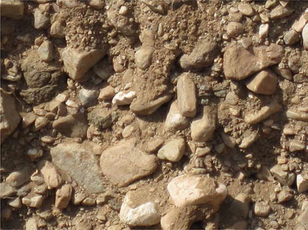
It is of paramount importance to grasp mechanical and physical properties of the coarse grain soils to be encountered when the EPB shield tunneling method will be utilized. Presented in Fig. (1) is the typical sandy gravel/cobble soil with boulders found in building Beijing subway tunnels. Main characteristics of the coarse grain soils disclosed in China subway tunnel construction can be briefly summarized as follows:
- Typical physical and mechanical properties are the large content of 30-70% by volume of coarse grains (gravel, cobble, and boulder), the general grain size of 30-200 mm with the maximum size of over 500 mm and the uniaxial compressive strength of grains as high as 180 MPa, taking the coarse soils encountered in Beijing for instance. Particularly, in the tunnel project of Lot 3 of Beijing subway Line 9, the content of the coarse grains is as high as 80%, and the maximum particle size is more than 1000 mm.
- The coarse grain soils are of unfavorable plasticity and fluidity, which will bring serious abrasions to shield machines. In view of the high abrasivity of the sandy cobble/gravel soils with boulders, the primary wear on cutting tools and the secondary wear on the support structures such as the cutterhead, if not controlled, are excessive, and especially the cutting teeth made of hard metal (cemented carbide) is liable to flake off when subject to impacts of the over-sized particles.
- Being loosely cemented and with less cohesion, most coarse grain soils exposed are typically unstable strata and their mechanical properties are unfavorable for force generation and transmission, and the ground surface is liable to cave in if improper manipulations of the shield machines exist.
3. CUTTERHEADS, CUTTING TOOLS CONFIGURATIONS AND SHIELD CUTTERHEAD PERFORMANCES
3.1. Cutterheads and Cutting Tools Configurations
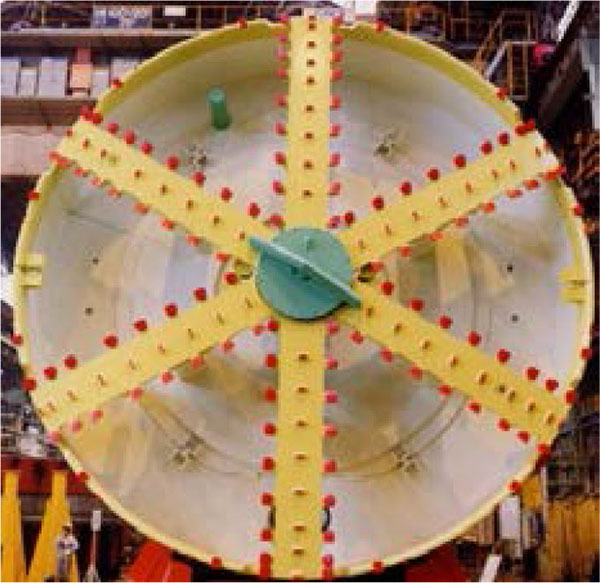
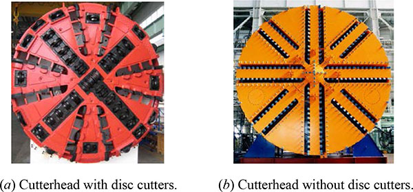
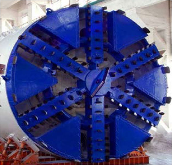
Advance of a shield machine is heavily dependent on its cutterhead as well as the combination and arrangement of the installed cutting tools. Generally, as shown in Figs. (2 & 3), there are basically two types of cutterheads for soft ground shield machines; one is the spoke type and the other is the plate type. The most significant difference between the two types of cutterheads is the discrepancy in opening ratio of the cutterheads, which is the percentage of openings of the total face area of a cutterhead. The advantages and disadvantages related to opening ratio of the two type’s cutterheads in excavating tunnels are displayed in Table 1.
| Items | Spoke Type Cutterhead | Plate Type Cutterhead |
|---|---|---|
| Pressure control of the cutting face | Being almost equal to the earth chamber pressure, the cutting face pressure is easy to be controlled. | On account of the indirect transmission between earth chamber pressure and cutting face pressure, it is a little difficult to perform precise pressure control of the cutting face. |
| Entry of muck into the excavation chamber | Entry of the excavated materials into cutterhead is smooth on account of the high opening ratio, almost resulting in no clogging of the cutterhead. | Affected by the plate, the entry of the excavated materials is not smooth and the cutterhead is liable to be clogged and jammed by the excavated materials. |
| Torque of cutterhead | The required torque of the cutterhead is small and the manufacturing price of the equipment is low. | Necessitate high torque of the cutterhead and large capacity of the equipment, as leads to a high construction cost. |
| Wear of the cutterhead and cutting tools | The high opening ratio of the cutterhead causes the relatively minor wears of the cutterhead and cutting tools. | Because of the small opening ratio of cutterhead, the excessive wear of the cutterhead and cutting tools is a hackneyed phenomon. |
| Adaptability to the over-sized particles | Over-sized grains or boulders that can’t be extracted from the excavation chamber by the screw conveyor must be handled by manual work. | Kept out of the cutterhead, the over-sized grains or boulders can be broken by disc cutters. |
| Safety of changing tools | The high opening ratio of the cutterhead to some extent decreases the stability of the cutting face. | The plate is helpful to stability of the cutting face, and a higher construction safety results. |
| Requirements for shield machine manipulations | The requirements are relatively high. | The requirements are relatively low. |
The prevalent excavation tools used for the spoke type cutterhead include tooth bits (scraper, ripper), shell bits, precut bits (ripper) and a center fish-tail bit (nose cone ripper). The idea of this combination of tools is to loosen ground before cutterhead with the center fish-tail bit and the precut bits, and rip off the over-sized stones out of the soil matrix with rippers, and shave off the weak materials with scrapers. When the plate type cutterhead is employed for shield machines in the coarse grain ground, disc cutters in combination with soft ground cutting tools (scraper, ripper and pick) are usually mounted on the cutterhead, and the installed disc cutters are tools to break big cobble/boulders into pieces, and the remaining work is fulfilled by the soft ground tools.
3.2. Performances of Shield Cutterheads
The two types of cutterheads are both adopted in China subway/metro construction to dig tunnels in the coarse grain soils, but received different responses. Effects of the cutterheads equipped with the corresponding cutting tools are revealed and illustrated by the following construction cases.
3.2.1. Cases of Using the Plate Type Cutterhead
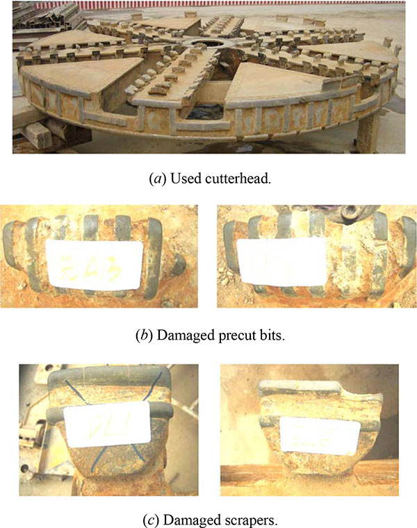
(1) The plate type cutterhead EPB shield was used in some project of Beijing subway Line 5. After driving 346 m, the machine slowed down and a sharp increase in the torque of cutterhead took place. Through looking over the cutterhead with access to the plenum (excavation chamber), it was observed that the four pairs of scrapers at the outer side of the cutterhead were totally worn out and the face scrapers were also seriously abraded (see Fig. (4)) and this was also true of the main body of the cutterhead. After restoring the cutterhead with repair welding, reinstalling all side scrapers and replacing 68 face scrapers, the shield machine started to work again. The main reasons for the excessive wears are as follows: the small opening ratio less than 30%; the four-spoke design and not enough scrapers; large forces acting on the scrapers on account of not installing precut bits and center fish-tail bit.
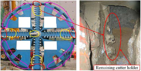
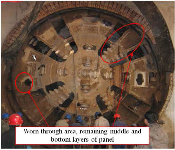
(2) A running tunnel on Beijing subway Line 4 was bored by an EPB shield machine equipped with disc cutters. The construction work was completed after many times of replacements of disc cutters. It was observed from Fig. (5) that the cutterhead and the cutting tools were seriously damaged, all top layers of the breasting plate located out of the central area of the cutterhead fell off, and the space between the remaining middle and bottom layers of the plate was full of muck. The causes for the damages can be summarized as: the small opening ratio of about 25% of the cutterhead; no enough reaction forces on disc cutters resulting in abnormal wears of disc cutters; not installing precut bits including nose cone bits and excessive secondary wears by rolling of the over-sized grains between the breasting plates and the cutting face.
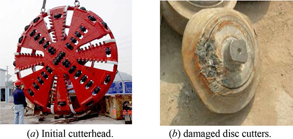
(3) Two EPB shield machines with plate type cutterheads were adopted in building running tunnels of some project of Chengdu metro line 2. The opening ratio of cutterhead is about 20% and not equipped with precut bits, as shown in Fig. (6). Due to the large content of over-sized particles, the abnormal wears of the disc cutters were serious and frequent replacements of tools were performed per 50-100 m. After changing types of the alloys and workmanship for the scrapers, installing new scrapers in some disc cutter boxes, and welding the reinforced-type precut bits to the cutterhead, the boring length before the next replacing tools was increased to more than 300 m. The reasons for the tough driving work are as follows: small opening ratio of about 20%; unreasonable configurations of cutting tools and cutterhead. The driving distance was only prolonged by the improved cutting tools because of the unmodifiable structure of the cutterhead.
3.2.2. Cases of Using the Spoke Type Cutterhead
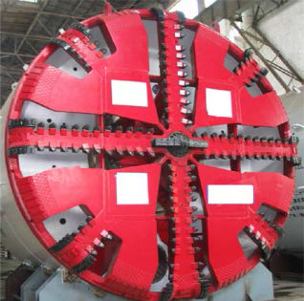
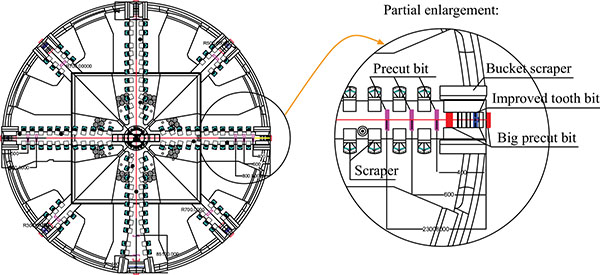
The spoke type cutterhead was ever widely used in Beijing shield tunneling. In the following construction cases the shield machines of 6.14 m diameter are employed, and the cutterheads are given in (Fig. 7). The six cylindrical spoke type cutterhead with opening ratio of 75.5% is equipped with 82 scrapers, 28 precut bits (ripper teeth), 12 shell bits, one center fish-tail bit and two copy cutters, as presented in (Figs. 8-11).
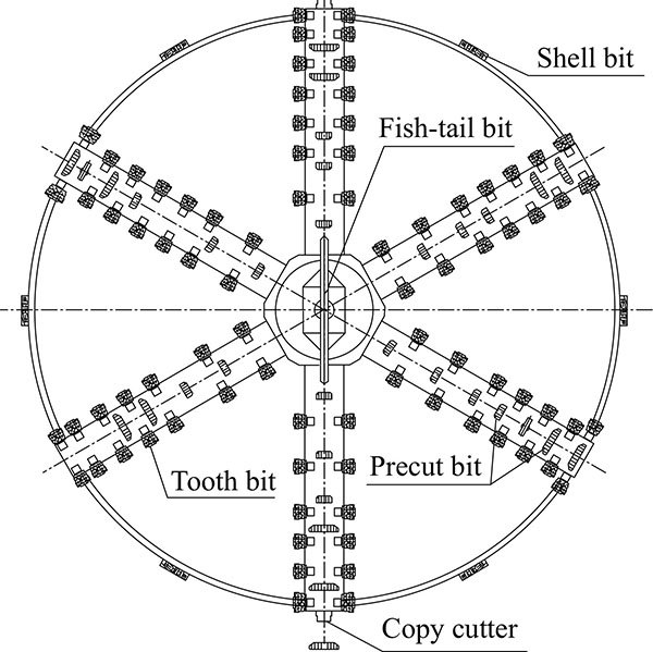
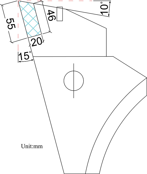
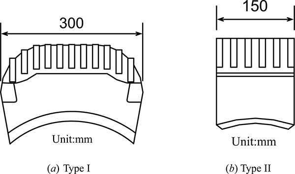
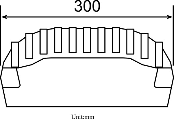
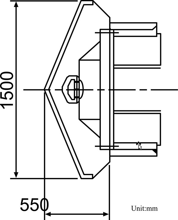
The rake and clearance angles of the scrapers with the attachment chip of 55 × 20 mm size are 15° and 10° respectively. The Type I precut bits are installed at the outer area of the cutterhead whereas the Type II precut bit mounted at the inner area of the cutterhead. The precut bits are 50 mm higher than the scrapers. The shell bits, which can be taken as precut bits, are mounted at the periphery of the cutterhead aiming at protecting the cutterhead and reducing frictions between the cutterhead and the soils. The fish-tail bit at the center of the cutterhead is 440 mm higher than the scrapers.
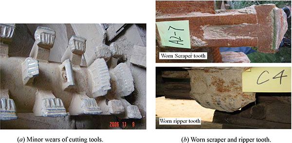
(1) The Lot 14 of Beijing subway Line 4 is constituted of three twin running tunnels sectors and two underground stations. The three twin running tunnels, mainly buried in sandy gravel and cobble ground with the maximum grain size of more than 200 mm, are 0.82 km, 1.47 km and 1.33 km in length respectively. The first running tunnel of 0.82 km long was finished with minor wears (see Fig. (12a)). Subsequent to repairing some cutter bits with surface welding, the second running tunnel, 1.47 km in length, was bored and after completing the second tunnel it was found that the scrapers were seriously damaged but the blades of the ripper teeth were basically remained (see Fig. (12b)). Before driving the third running tunnel of 1.33 km long, extensive repairs were performed for cutting tools, which later guaranteed the smooth completion of the third tunnel construction without changing tools.
(2) The Lot 11 of Beijing subway Line 10 comprises two twin running tunnels 2.1 km and 0.7 km in length respectively, located in sandy gravel\cobble ground. According to the geological investigation, the cobble with grain size more than 15 mm accounts for as much as 45% by volume and the SPT values are 60-65. After finishing the first running tunnel of 2.1 km long, it was observed that the wear amounts of the cutting tools were significantly less than the theoretical values. Subsequent to repairs of cutting tools with surface welding, the second running tunnel was also completed without interruption.
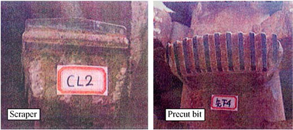
(3) The same type shield machine was adopted in constructing a 0.82 km long tunnel in sandy gravel/cobble soils, of Lot 18 of Beijing subway Line 5. The smooth driving without replacing cutting tools was achieved, and the scrapers and the ripper teeth were still in good shape (see Fig. (13)).
(4) The same type shield machine was also utilized in digging a 1.02 km long running tunnel of Lot 9 of Shenyang metro Line 1. The running tunnel mainly passed through the sandy gravel/cobble soils with the maximum grain size of 100 mm. The tunnel was finished without changing cutting tools. Only a few wears of the cutterhead and most cutting tools were found except some seriously abraded tooth bits (see Fig. (14)).
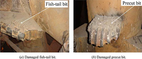
(5) The same type shield machine was also adopted in driving a 1.17 km long running tunnel of Lot 13 of Shenyang metro Line 1. The gravel/cobble with grain size more than 20 mm accounted for 20-30% of the total weight, and the maximum grain size discovered was 110 mm. The tunnel was completed without replacing cutting tools. After arrival of the shield machine, it was seen that most damages of the cutting tools were caused by collisions. As shown in Fig. (15), the scrapers were seriously collided and part tip of the center fish-tail bit was broken off and the two sides of the ripper tooth were damaged though it remained good shape and could still work.
3.2.3. Cases of Using the Spoke-plate Type Cutterhead
(1) The running tunnels of Lot 4 of Beijing subway Line 4 were bored using two shield machines equipped with the spoke-plate type cutterhead of 39% opening ratio, as shown in (Fig. 16). The ground is very much alike that encountered at Lot 14 of Beijing subway Line 4 mentioned above. The combination of cutting tools is very similar to that used in Lot 14 of Beijing subway Line 4, consisting of 94 scrapers, 40 precut bits, 12 shell bits, one center fish-tail bit and two copy cutters. The running tunnels were finished without changing tools. The cutterhead and some tools after driving are presented in (Fig. 17).
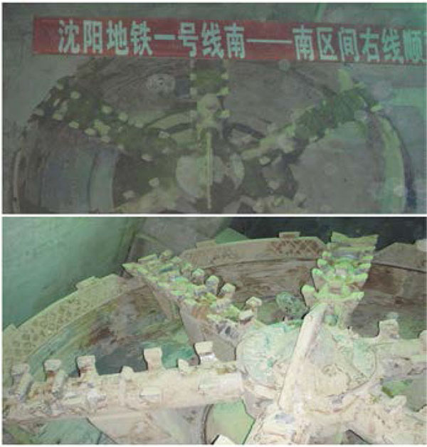
(2) As shown in Fig. (18), the spoke-plate type cutterhead with opening ratio of 27% was used in building running tunnels of Lot 9 of Shenyang metro Line 1. The tunnels mainly passed through the sandy gravel/cobble soils and the maximum size of particle was about 200 mm, and the initial cutting tools were face scrapers and circumferential bucket scrapers. After driving the No. 193 ring, the cutterhead and cutting tools were seriously destroyed. Main retrofitting jobs included wear resistant plating for cutterhead, installing 28 precut bits as well as repairing damaged scrapers and tooth bits (see Fig. (19)). Using the improved cutterhead and cutting tools, the remaining part of the tunnel was bored without interruption.
4. DISCUSSIONS AND SUGGESTIONS
Though configurations of the cutterhead and tools of a shield machine must be customized for specific ground conditions, some options with respect to key parameters of the configurations can be deduced from the above-mentioned construction cases.
4.1. Opening Ratio of Cutterhead
Although the opening ratio of a cutterhead is the result of a compromise involving a large number of aspects, a high opening ratio of the shield cutterhead used in sandy gravel/cobble soils with boulders is a better choice, as has been proved by the many above cases of using the spoke type and spoke-plate type cutterheads. In these cases, the tunnels were bored without change cutting tools. Whereas in the cases of using the plate type cutterheads with low opening ratios of 20%-30%, the interventions for replacing cutting tools are indispensable to realizing driving of the whole tunnel at the expenses of additional time and money. The spoke type and spoke-plate type cutterheads with high opening ratios of 39-75.5% are favorable to passing of the ripped-off big stones into the rear mixing chamber without the need of a substantial pressure drop, thus mitigating wears and damages of cutting tools and other components as well as reducing interventions of changing tools. This is one of the main reasons why the spoke type cutterhead is widely adopted in Beijing to construct subway tunnels.
The optimal opening ratio of a cutterhead exists, as can be deduced from the calculated wear coefficients of cutting tools in the projects of Lot 4 and 14 of Beijing subway Line 4. The wear coefficient is defined as the wear amount dividing by the tool path length. The involved strata are almost identical and configurations of the cutting tools are very alike, as previously mentioned. The average wear coefficients for precut bits, including shell bits at the periphery, of the two cutterheads are about 0.035 mm/km. The average wear coefficients for scrapers of the spoke type and the spoke-plate type cutterheads are close and are 0.0081 and 0.0068 mm/km respectively. The wear coefficients for scrapers in the two cases are both less than 0.01 mm/km, only 1/4 of those for precut bits, as shows that the scrapers play the role of ripping off, agitating and not shaving off ground. So, it is concluded that the two opening ratios of 39% and 75.5% have almost the same influences on tool wears and are both justifiable. However, the opening ratio of 39% is more reasonable if more considerations are given to the cutting face stability and shield machine manipulation. If shield tunneling will be performed in the coarse grain soils rich in groundwater and maintaining cutting face stability is a demanding job, a spoke-plate type, or plate type cutterhead with high opening ratio, such as 39%, for the specific ground condition is strongly recommended. As to deciding the site-specific opening ratio of a cutterhead, a good estimation of the size of grains in soils takes the lead. In Chengdu, most metro tunnels are constructed in water-rich coarse grain ground and the plate type cutterheads are usually employed mainly for the sake of more reliably maintaining stability of the cutting face.
4.2. Configuration of Cutting Tools
It is observed from the previous construction cases that there are two typical types of configurations of tools for the cutterheads used in coarse grain soils; one is for the spoke type or spoke-plate cutterhead with high opening ratio and the other is for the plate type cutterhead with an opening ratio less than 30%. Dependent on specific characteristics of the ground conditions and the suitable ground excavation mechanism, the cutting tools, including precut bits, shell bits, scrapers and a center fish-tail bit, are versatile combinations of tools for spoke type and spoke-plate cutterheads with high opening ratio in Beijing and Shenyang coarse grain soils, which has been displayed by the relevant construction cases. With the help of loosening soils by precut bits, shell bits and the center fish-tail bit beforehand, the oversized particles (cobbles and boulders) can be easily ripped out of the soil matrix causing less thrust and less torque of a shield machine as well as rapid tunnel construction. Of course, a shaftless ribbon type screw conveyor is often indispensable to smooth discharge of the large sized grains in the excavated materials.
The plate type cutterheads with opening ratio about 30% are widely used in Chengdu metro tunnel construction mainly on account of the soils rich in groundwater. The tools used at the beginning of tunnel construction were disc cutters in combination with scrapers presented in (Fig. 6a). Standing out a little farther in profile, the installed disc cutters were to break big cobble/boulders in soils into pieces and loosen ground in front of the cutterhead at the same time, but often suffered severe wears only after a driving less than 100 m and frequent changing tools work had to be performed. It was one of the most important improvement measures taken in Lot 22, Lot 11 of Line 2 and Lot 4 of Line 1 of Chengdu metro that precut bits were added or used to replace some disc cutters. The driving length was increased to 300 m or even more before necessary interventions of changing tools. Therefore, for the plate type cutterheads, the combination of precut bits and scrapers with/without disc cutters may be a better choice.
Because scrapers are vulnerable to big cobbles and boulders in ground excavation, proper height differences between precut bits and scrapers are especially important to play different roles of the two types of tools. For example, the differences are in the ranges of 40-50 mm in Beijing sandy gravel/cobble soils. Meantime, in view of good performances of the previous cutterheads with precut bits, the precut bits should be strong enough to help reduce wears of the scrapers to the minimum.
4.3. Use of Single Disc Cutters with Inserts
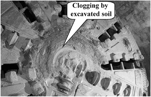
It is very common for shield tunneling in the coarse grain soils that the installed center disc cutters and single disc cutters suffer excessive abnormal wears. At a low rotation speed of the cutterhead, the center disc cutters are easily jammed by clogging of the cutterhead (see Fig. (20)). The single disc cutters have a single point of contact at the face and tend to skid or be stagnant in the soft or not compact soils, wearing flat on one side and making excavation of the over-sized particles difficult. Frequent work of changing cutting tools at more time and expenses has to be executed during the whole tunnel construction. Whereas, disc cutters with tungsten carbide inserts can excavate cobbles and boulders with a higher efficiency because they have multiple points of contact at the face. The multiple buttons act like traction, allowing the carbide cutters to ‘grip’ in soft or loosened ground and keep rotating. As compared to performances of the twin disc cutters, it was found that the twin disc cutters were more easily worn out than single disc cutters when building a railway tunnel in Beijing sandy gravel/cobble soils with boulders [32]. So, it is recommended that the plate type cutterheads equipped with the chip inserted single disc cutters in combination with the more aggressive soft ground tools are adopted when boring tunnels in the water-rich coarse grain soils.
4.4. Reasonable Movement of Shield Machines
As cutting tools move in the excavation face they are taking up highly viable loads. The wear and failure of the tools is the result of such cyclic loadings. As revealed in Figs. (15, 17), dropping off of tips and fractures of cutting tools are prevailing damages caused by cobbles or boulders when they abruptly hit these over-sized particles. To mitigate the adverse effects, deciding the slow and reasonable movements (advance, rotation) of a shield machine is of great importance. Particularly for hard boulder-laden ground when using disc cutters the penetration rate per cutterhead rotation should be well regulated and restricted to avoid that boulders will be ripped-out of the soil matrix, endangering the stability of the cutting face and damaging cutterhead and cutting tools. For a spoke type cutterhead shield machine, the well planned sensible and slow movements for the specific ground conditions can greatly reduce the damages to precut bits as well as to scrapers caused by collisions with big cobbles or boulders.
4.5. Robust Shield Machines Again Wears
The wears and damages to cutting tools, cutterhead and other components do exist if shield tunneling will be performed in the coarse grain soils. Particularly, when a long tunnel will be constructed, it is absolutely necessary to take whatever, state-of-the-art measures to reduce the adverse influences. In recent years, large improvements have been achieved in relation to the cutting tool durability and wear protection on cutterhead as well as other components of a shield machine [33]. The highlights are more specialized, robust wear resistant tools. These robust tools, such as pressure compensated disc cutters of monobloc design including options with carbide inserts, soft ground tools (scrapers, rippers) using carbide cutting edges or inserts in combinations with hardfacing, will allow for a longer lifespan of the cutting tools under the coarse grain ground conditions. Using lately developed twin layer plating materials, overall replaceable wear protections of the cutterhead in weld-on or bolted-on designs can also be effectively applied to the shield machines in coarse grain soils [34, 35]. The designs consist of wedges to protect the cutters, wear plates for the face, wear protection at the cutterhead periphery, grill bars to protect the cutterhead periphery, and grill bars to protect the scrapers from big blocks and control the maximum block size to enter the cutterhead.
4.6. Interventions for Changing Tools
Interventions and chamber access for repairing tools and other components are sometimes indispensable to some demanding and challenging works of the tunnel construction in coarse grain soils. Compared with changing cutting tools under compressed air condition, changing tools in free air, or “atmospheric cutter change” based on a hollow cutterhead structure for a large diameter shield machine [33, 35], is a better choice. On the other hand, reliable information about conditions of the cutting tools is an essential factor to minimize interventions to the necessary minimum and reduce risk of the extended compressed air work for repairing damaged tools and cutterheads. Using ultrasonic inspection equipment to detect wear of the cutting tools remains a promising approach with the ongoing development of the relevant technologies [22, 28].
CONCLUSION
Based on the above statements and discussions, the following is concluded:
- The spoke type cutterheads equipped with precut bits, shell bits, scrapers and a center fish-tail bit are strongly recommended for the shield tunneling in loose coarse grain soils without groundwater.
- The spoke-plate or plate type cutterhead with reasonable opening ratio is a better choice if the first priority is to guarantee stability of the cutting face or mechanized driving will be performed in ground conditions rich in groundwater. The reasonable opening ratio of a cutterhead can be decided based on a good estimate of the size of particles in soils as well as experiences from the previous similar construction projects.
- Reasonable combinations of tools and proper height differences among tools for the specific particle size distributions are of paramount importance to realize the efficient boring of tunnels in the coarse grain soils. Especially, the precut bits are suggested to be installed on both spoke type and plate type cutterhead on account of good performances revealed. The disc cutters, if mounted on cutterheads, will be single disc cutters with tungsten carbide inserts.
- Enough aggressive tools and robust cutterheads allowing for longer driving in the coarse grain soils are suggested to be prepared or reserved to ensure the scheduled construction time lest the unforeseen scenarios or more difficult ground conditions will be encountered
- In the case that interventions and chamber access for changing tools are indispensable, the tools replacement plan should be well planned beforehand and the operation procedure should be well prepared, as is helpful to reduce adverse effects caused by the over-sized particles on shield tunneling.
CONFLICT OF INTEREST
The authors confirm that this article content has no conflict of interest.
ACKNOWLEDGEMENTS
The authors gratefully acknowledge the financial support by the National Basic Research Program of China under Grant 2015CB057800.

