All published articles of this journal are available on ScienceDirect.
Construction and Retrofit Methods of Stone Masonry Structures in Cyprus
Abstract
Natural stone is a durable construction material which has been used through centuries for various types of structures. These structures are exposed to corrosive and degradation factors such as climate change and pollution, natural ageing, earthquake actions, increasing urbanization and even human negligence, potentially exposing them to irreversible structural damage and loss. Considering the large number of traditional structures and the historic value of a great number of stone masonry structures, the necessity of maintenance, repair, retrofit and restoration of stone masonry structures is imposed. The process which leads to the preservation of such structures consists of three stages: 1) the in-situ and laboratory study of the degree of damage and of the factors which cause the natural damages on the materials of these buildings, 2) the detailed drawing of the layout and the elevations. This stage also includes the selection of the appropriate measures for the maintenance and retrofits according to the special characteristics of the structure and the design of the intervention method, and 3) the execution of all the intervention works. This paper presents a description of various types of natural stones found in Cyprus, the most commonly used construction methods as well as methods for the retrofit of stone masonry structures.
1. INTRODUCTION
Stone masonry structures lie in the heart of the wider subject of cultural heritage and as such the need for their preservation is nothing but a mere understatement. The preservation of stone masonry structures for future generations does not just make sense from a scientific and aesthetic point of view but also their protection in the face of global change is becoming a major concern for decision-makers, stakeholders and citizens in Europe. Apart from natural ageing, these structures are exposed to such synergistic threats as geological changes, climate change and pollution, increasing urbanization and even human negligence. Environmental changes and security risks menace stone masonry structures, potentially exposing them to irreversible structural damage and loss because of age and fragility. This paper attempts to present the present state of Cyprus which has a long history and a great natural stone masonry building stock. First, the paper provides a description of the most common indigenous natural stones which are the major construction material and also the most common material used for intervention works. Presented next are the predominant construction methods which are also very common not only in Cyprus but the surrounding area as well. The process for the determination of the type and extend of the intervention method is presented next and following that is a presentation of common methods that are used for the retrofit of stone masonry structures.
2. NATURAL STONES OF CYPRUS
The rich geological formations in Cyprus allowed the use of natural stones in the construction of traditional buildings and settlements such as the Neolithic settlement of Chirokitia, dating back to 7,000BC. Cyprus is situated in an active seismic region and the use of natural stones for new construction is not very common. However, the large stock of stone masonry structures many of which have great archaeological importance requires systematic maintenance and upgrade; consequently the use of natural stone for the intervention works is not only necessary but also continuous. The most common natural stones in Cyprus together with a brief description of their properties are presented in this section.
2.1. Calcareous Sandstone of Pachna Formation
This stone is found in the outcrops of the Pachna [1] geological formation (Fig. 1). It is used extensively in the Cyprus building industry as it satisfies a number of specifications such as ASTM-C568, NFB10/509 and NFB10/51. It is a fine grained holocrystalline rock of beige-yellow color which has been formed through the cementing of grains of limestone chalks, quartz, plagioclass and pyroxenes with calcium carbonate through diagenesis on the sea floor [2].

Calcareous sandstone of Pachna formation [3].
2.2. Calcareous Sandstone of Nicosia Formation
The stone is quarried from the hills around Nicosia [1] and a number of famous structures are characteristic constructions using this particular stone. It is a holocrystalline porous rock relatively coarse-grained with fragments of calcium carbonate cemented with secondary calcite [2]. Its crushing and flexural strengths are much lower than that of the calcareous sandstone of the Pachna formation and its color is yellow-ochre (Fig. 2).

Calcareous sandstone of Athalassa formation [3].
2.3. Cherts
Compact rock, very hard and brittle and amorphous of light, ochre and grey color (Fig. 3). It is a bedded rock with varying thickness from 10-25cm and alternates with the bedded chalks and marly chalks of the Lefkara geological formation [2]. It is very resistant to weathering and has been used since neolithic times not only in the building industry but also to make tools before the discovery and use of copper and iron.
2.4. Chalks
Massive or bedded fine grained rock [1] resembling chert but much less resistant to weathering (Fig. 4). It is found in beds 10-25cm thick alternating with cherts and marls or as massive thick beds which are easily cut in slabs of various dimensions and thicknesses. In the geological formation of Lefkara the snow-white chalks are very common, while in the geological formation of Pachna the chalks have beige to grey-yellow color.
2.5. Intrusive Roks (DIABASE)
The diabase covers more than one third of the Troodos mountains range. It is used in the building industry more than any other igneous rock of Troodos (Fig. 5). It is hard, compact, holocrystalline rock, very resistant to abrasion and weathering [4]. It is quarried extensively for the production of crushed gravel and sand for the building industry. It is grey in color and is used extensively as a building stone in the Troodos villages.
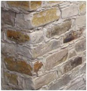
Chert rock - Wall construction [3].
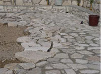
Construction of pavement from calcareous chalks [3].
Other types of stones that are used in a much smaller scale include: the Flysch, Gabbro and dunite (Plutonic Rocks), etc. Also in use is the recrystallized limestone from the Mammonia formation found in the Kyrenia range and in Paphos. A famous formation, related with the tradition and the medieval history of Cyprus, which is known as “Petra tou Romiou”, is an example of this type of rock.
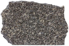
Diabase [4].
3. TRADITIONAL STONE MASONRY CONSTRUCTION IN CYPRUS
The climate, the landscape, the environment and the availability of materials affect the design and morphology of a traditional structure to be entirely in tune with its surroundings. Stone is used more broadly than just for residential buildings. Such uses include churches, public buildings, wine presses, water mills, bridges, aqueducts etc. In many places dry-stone walls (Fig. 6) are considered natural monuments.
3.1. Classification Schemes of Masonry Walls
The stone walls are divided in two major categories based on the precision with which the natural stones are cut and placed:
- Ashlar: stones are precisely cut, leading to relatively small mortar joints
- Rubble: stones are roughly cut, or used as found, leading to relatively large mortar joints
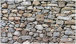
Dry-stone wall constructed with igneous rocks [3].
In addition, the pattern in which the stones are placed on the wall leads to another classification scheme:
- Coursed: stones are placed in horizontal rows
- Random: stones are placed without any particular order
Further classification schemes result from the combination of the major categories and patterns as shown on Fig. (7).
3.2. Methods of Stone Masonry Construction
Masonry walls normally consist of two parts with an infill in between. The construction requires two builders, one on each side, with the more skilled one laying stones on the exterior face that normally remains un-plastered. The interior face of the wall is normally plastered so a rougher face is acceptable. The two parts are tied together with the use of tie-stones, spaced roughly every one meter in length and height. The core is generally filled with rubble and gypsum-based mortar or earth-based mortar. The total thickness of the wall, both in ashlar and rubble configurations ranges between 50cm to 120cm. The walls are founded on stone foundations or where the topography permits on solid rock. Stone masonry construction varies according to the stone cut (ashlar or rubble) and also according to the type of gallets (pebbles) the masons use as infill in combination with the mortar joints. The type of pebbles depends on the type of local materials available and can be replaced by other type of material such as pieces of terracotta tiles. Usually river-bed pebbles and small local stones are used. In urban architecture, ashlar stones are used more often, predominantly calcareous sandstone, which can be cut to accurate shapes (used in regular or masonry construction) whereas, in rural architecture, random rubble construction is used more often. Exceptions in rural architecture include the use of ashlar configuration for the construction of village churches or luxurious houses and buildings that belonged to reach people.
3.2.1. Random Rubble Masonry Construction
This construction method requires the stone to be cut to its rough form. This is done on site. The sharp protrusions are removed, normally with the use of a hammer in order to create the basic surfaces necessary for building. The exterior face of the random rubble masonry should be as leveled as possible and may project beyond the line of the joints as opposed to the ashlar masonry construction. The special feature found in the random rubble masonry construction is the use of gallets. They are used to fill the gaps between the larger stones and to complete the horizontal line of each bed joint (Fig. 7). In order to achieve good results for the construction of walls, it is necessary to follow the rules of random rubble masonry construction, such as maintaining staggered vertical joints, the use of tie-stones and the balanced distribution of the various sizes of stones throughout the entire area of the wall. At the corners of the buildings the stones have to be crossed to ensure that perpendicular walls are tied to each other. Different variations of random rubble masonry construction can be found depending on the type of stone used. Wherever random rubble calcareous sandstone or igneous stones are used, in which case the stones are large and irregular, the construction is coarse and random as opposed to the flat and well defined horizontal bed orientation of the walls consisting of cherts and chalks.
3.2.2. Isodomic Masonry Construction
The isodomic masonry construction follows the same guidelines as the random rubble construction. The difference lies in the fact that it requires the use of ashlar stones which are cut prior to placement. The isodomic masonry construction only begins after leveling (vertical and horizontal). The joints in this case are thin and they are in line (Fig. 8).
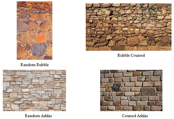
Classification schemes of stone masonry construction [3].
The various rocks used are kept in place with the aid of mortars. The most common types of mortars that are normally used in Cyprus stone masonry construction are the Adobe (earth), Lime and Gypsum.

Isodomic masonry construction [3].
4. DECISION FOR INTERVENTION
The type and level of any intervention work will be based on measurable criteria which will be defined by the involved parties such as the owner of the structure, the consulting engineers, and the legislative framework if the structure has archaeological value. The current state of the structural integrity will be based on the diagnosis of damages. The building identification will provide the information for structural modelling and the calculation of the internal stresses by means of a suitable commercial package. The preferred type and level of the interventions will be specified in the design stage.
4.1. Damages
The major cases of damage basically stem from the inability of stones to support tension. The consisting elements for stone masonry structures are mainly designed to be in compression and therefore the walls are load bearing. The damages in stone build structures can be categorized as:
- Indirect: damage of secondary elements such as internal walls and staircases which do not affect the structural integrity of the structure
- Direct: damage of primary elements such as load bearing walls that are part of the load resisting system of the structure
The major indication of damage is the presence of cracking which can be the result of excessive tensile stresses from the relative shift between two elements or from excessive compression and/or bending accompanied by buckling.
Various factors can be the sources of damages. Climatic factors such as the temperature variations cause the alternating expansion and shrinkage which results to the relaxation of material bonding and consequently the generation of cracking. The presence of water in cavities which can freeze and thaw can also initialize or increase cracks aiding the intrusion of other deterioration agents such as SO2, NO2 (i.e. atmospheric pollution) contributing to the erosion of the material. Further, the presence of humidity in the stone walls favours the growth of such organisms as mosses and lichen which burden the structures with the resulting biochemical actions. Geological factors comprise another major source of damage; earthquakes constitute perhaps the most devastating cause capable to result to the complete collapse of a stone build structure. The presence of settlement is also a problem which can be the result not necessarily of the building loads but the actions of the surrounding environment such as ground vibrations due to adjacent developments or demolitions, any extensions to the original structure, or even the excavation of a nearby foundation. Each of these actions causes different types of problems however the synergistic effect results to the acceleration of damages. Considering that the envelope of the damaging actions can be represented by a function with respect to time S(t), and also assuming that R(t) is a function that represents the resistance of the structure with respect to time then for any given time we are interested that [5]:
| S(t) ≤ R(t) | (1) |
If the above inequality ceases to be satisfied at any time, intervention works are necessary to prolong the life of the structure.
4.2. Damages Identification
The assessment of the remaining strength of a structure includes the identification of damages as it will reveal weaknesses of the structure and define the level and type of intervention. Normally in-situ as well as laboratory testing (non-destructive or semi destructive) is necessary. The most common method for the diagnosis of damages is the visual inspection which is very quick and cost effective. Visual inspection is mainly used to detect surface problems such as cracks. Data collected during visual inspection is related to the geometry (dimensions such as width, height and length), width of cracks, size of deformations etc. Other methods must also be used to quantify the level of damage such as the weight-on-bit-method, the torque method, chemical methods etc.
4.3. Building Identification
The detailed and complete determination of the current state of the structure is of paramount importance prior to any intervention. This requires the development of a report including the data which will lead to the decision for the best course of action for the intervention. The report should consist of [5]:
- The “as is” plans of the structure. These include the site plan, the plans, the elevations as wells as section plans. In addition, it is very informative if a number of detail plans for various parts of fixtures on the building are developed. All those plans should present the current state of the structure including the detailed dimensions and elevations, the healthy parts of the structure, the defects, the possible presence of any plant growth or eroded material etc.
- The history of development of the structure describing the phases of construction if possible, the later extensions or subtractions and also any interventions
- The properties of the constituting materials such as specific weight, natural humidity, density, content of any chemical substances etc. Further, it should include the mechanical properties such as the compressive strength, the resistance in tension, modulus of elasticity etc.
- Geotechnical survey of the site including the bearing capacity of the ground. This is very important to determine if any future intervention is possible
- The building structural integrity assessment including the capacity under possible actions of loading, potential earthquakes extreme weather
4.4. Analysis and (Re)Design Stages
The analysis and design of a stone masonry structure is not an easy task mainly because of the presence of the load bearing elements. As such the modelling is difficult. The first stage includes the study of the building identification report. When the damage diagnosis is complete, the assessment of various intervention types based on specific criteria follows. Once the assessment is complete the intervention method will be proposed and a set of specifications for the execution of the works will be developed. The design stage can be summarized as follows [6]:
- Detailed damage identification based on on-site and laboratory experiments
- Definition of the material mechanical properties
- Assessment of intervention types alternatives, specification of criteria and decision of the preferred intervention type and level
- Definition of the legislative requirements. The relevant specifications are set by the Eurocodes
- ○ EC0: Basis of structural design
- ○ EC1: Actions on structures
- ○ EC6: Design of masonry structures
- ○ EC7: Geotechnical design
- ○ EC8: Design of structures for earthquake resistance
- Setup of the analysis model based on the following definitions
- ○ Load bearing system
- ○ Damage level at various points of the structure
- ○ Material mechanical properties
- Determination of the design loads (i.e. earthquake loads from EC8), and the appropriate load combinations
- Analysis (static and dynamic) of the structure for the determination of the internal forces. Normally the analysis is performed with the aid of software implementing the finite element method
- Preparation of architectural and construction drawings with detailed presentation of the connections and areas of high stress concentrations
- Preparation of the specifications as well as a health and safety plan
- Supervision plan for the intervention works
5. RETROFIT METHODS FOR MASONRY STRUCTURES
Depending on the type and location of the damage there are a number of methods that can be applied for retrofitting stone structures. Although other methods for retrofitting may exist, the intention of this paper is to present those that are most commonly used in Cyprus. It should also be reiterated that the decision for any type of intervention belongs solely to the consultant engineer.
5.1. Restoration and Reconstruction of Masonry Walls
Restoration or reconstruction of masonry walls normally involves the failure of one of the two leafs, most commonly the external. In any case it will require the reconstruction of the faulted part and strengthening of the connection using tie-stones (Fig. 9).
The procedure involves the following:
- The reconstruction must incorporate new stones of a similar type, size and proportion as those of the original wall, in order to achieve a homogeneous construction between the new and the old. If possible, the original stones from the ruined section should be used
- Careful cleaning of masonry using low abrasive tools and water. It is recommended that a brush and sand paper be used, while high pressure sand blasting and extreme mechanical cleaning should be avoided in order to prevent damage to the stone
- Stones should be bedded horizontally
- Gallets should be built horizontally using very fine joints
- The laying of stones and gallets should be done in such a way as to maintain a horizontal line approximately every three courses
- Continuous vertical joints must be avoided
- Pointing should be recessed at about 0.5-1.0cm from the exterior face of the stones and be placed neither deeper than the exterior surface nor protruding from the wall
- Lime mortar should be used both for pointing and applying gallets. During these processes care should be taken in order to keep, as much as possible, the exterior surface of the masonry stones clean
- The two sides (leafs) of the masonry wall should be connected with tie-stones. The tie-stones should be placed at intervals of approximately 1.00m along the total length and height of the wall
- Additional bonding of the two sides of the wall, if necessary, using glass-fiber mesh at intervals of about 0.60m along the total height of the wall
- After completion of construction the wall should be brushed down and cleaned with water if necessary (Fig. 10).
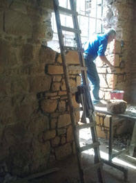
Reconstruction using tie-stones [3].
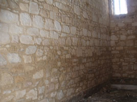
Stone wall construction (elevation) [3].
5.2. Overlapping Courses Using Tie Stones
The use of tie-stones is essential in the presence of cracks due to unconnected courses. The following procedure is essential:
- The crack is carefully widened and cleaned by brushing and washing using low abrasive tools and water
- Stones are removed along the edges of the crack every 0.50m and they are replaced with tie-stones
- Pointing is removed along the length of the crack at 0.50m on both its sides. Pointing is retained if it is very well preserved
- After the tie-stones are in place, gallets and/or pointing takes place using lime mortar (Fig. 11)

Crack restoration with tie-stones [3].
5.3. Tying Courses Using Steel TIE-Rods
In addition to the tie-stones that are presented in the previous section there are cases that steel tie-rods can be used to tie courses together using the following procedure:
- The crack is carefully widened from loose stones, mortar and gallets and the opening is cleaned using low abrasive tools and water. The crack is widened at a depth of 0.15m on both sides of the wall (Fig. 12).
- Mortar and gallets are removed from both sides of the crack at 0.75m on each side at a depth of 0.15m. The opening has to be cleaned and then tie-rods (1.50m) are installed on both sides of the wall at intervals of 1.00m in height. The tie-rods must be rustproof.
- The crack must be filled in with stones and gallets and re-pointed with lime mortar in order to complete the wall.
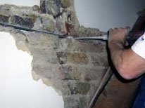
Crack widening by removing the mortar, loose stones and gallets [3].
5.4. Restoration of a Corner
When restoring a corner of a stone masonry wall then the following procedure is recommended (Fig. 13):
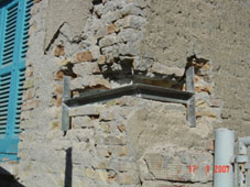
Reinforcing of the corner by galvanized metal element [3].
- Support of the roof and/or the floor
- Remove loose stones and gallets
- Reinforce the corner with rustproof plates of 1.20m minimum length in each of the two intersecting walls every 1.00m in height. Each plate must be embedded at least 0.60 m in each intersecting wall
5.5. Wall Connection by Metal Connectors (TIE-Rods)
Steel connectors (tie-rods) can be used to strengthen stone build structures against partial or total collapse and prevent lateral instability of the walls caused by the action of the horizontal structural members. The use of steel connectors is of great importance especially for masonry structures located in seismic zones (Fig. 14).
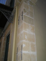
Typical steel connectors for stone masonry [3].
Although the observations of seismic damage showed significantly improved seismic behavior of the old buildings which have tied masonry walls, the practice to isolate the floors from the walls has been widely applied a few decades ago. In the normal course of rehabilitation and restoration after an earthquake or after various natural physical damages, the metal connectors are placed directly beneath the floor or at locations where it is necessary (cracking of walls at corners). For this reason, normal tendons can be used. The threaded ends are manufactured to be screwed to the ends of the wall onto a metal anchorage plates (Fig. 15).

Normal tendons (a) metal anchorage plates (b) corrosion resistant paint [3].
Usually, connections are placed symmetrically on both sides of the wall in horizontal grooves of width about 4-5cm that are created on the plaster connections just below the level of the floor to the wall surface. In such case the walls do not have to be damaged (Fig. 16).
The rods are held in place with staples placed in holes on the wall, which are opened at the joints. The anchorage plates have thickness of at least 15mm. The length of the plates is slightly larger than the thickness of the wall, while the width is less than 200mm. A slight pretension is applied in the rods with the use of a hand tool and the nuts are screwed on the plate. All metal parts are protected from corrosion with paint and then coated so that the connections are not visible.

Tendons installed to masonry wall [3].
5.6. Use of Grouting for the Repair and Strengthening of Masonry
Grouting is the process of injecting grout in the cavities of the wall and it consists of cement and water. The technique is applicable where the extent of the cracks of the wall does not exceed 1cm. This is an empirical technique even if it is in use for over a century. Grouting is described below:
- Prepare sample tests for various grout mixes depending on the nature of the works. The water is placed in a can and 2/3 of the cement is added. Then any admixtures are added and finally the rest of the cement. The mixture needs four minutes in a mixer with a frequency of at least 1000 rpm. After the mixing it is recommended that the cement based grout passes through a sieve No. 16 to remove any lumps
- The holes are then cleaned from loose material and dust and the edges are smoothed. Most of the times the grout is installed using high pressure. The grout passes through the gaps filling the vacuum and squeezing or pushing the air out of the gaps of the masonry. Knowledge of the internal structure of the wall and the percentage of gaps is an element of concern for choosing the most appropriate grout mix. Grouting is performed using rubber tubes with diameters ranging from 0.3 - 0.6m (Fig. 17) depending on the amount of grout
- Since the grout takes the place of air or of any water, care must be taken so that there are at least two holes next to each other. Grouting requires the involvement or supervision of experienced staff that can make decisions as to which grout mix to be used and the location of the holes. The distances between the tubes and the quantity of grout depend on the nature and viscosity of the grout, the pipe diameter, the permeability of the wall, and the intake pressure of the grout
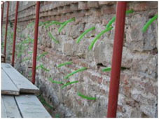
Installation of a rubber tubes in the wall for the installment of the grout [3].
- The initial pressure is kept constant and 30 MPa until the grout is absorbed by the wall (Fig. 18). Then it is increased to 40 MPa and held steady for 5-10 minutes so that the mixture is stabilized and excess water is drained. However high pressure can create problems to low strength masonry and for this reason the pressure to be used should be calibrated. The injection of the grout starts from the lower part of the wall and continues upward in a systematic way. The lower holes are filled first until there is an overflow of grout from holes at the higher level. Then the lower tubes are sealed. The next holes to fill are those that are overflowed by the grout injection at a lower level and the process is continued until all holes are filled (Fig. 19). In the case that grout is inserted in the wall but there is no overflow from a higher level hole then there is a problem which has to be addressed. Ways to do that include the drilling of holes at closer distance or the use of grout with less viscosity. When the process is complete the tubes are removed and the holes are covered with appropriate finish

Equipment for the control of the pressure [3].
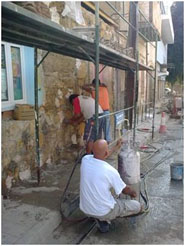
An overflow of grout from holes at a higher level [3].
CONCLUSION
The rich geological formations in Cyprus and its durability favored the use of natural stone as a construction material through ages. The climatic conditions, the landscape and the environment are factors affecting the design and morphology of a traditional structure to be entirely in tune with its surroundings. Natural stone has been used for the construction of old structures (i.e. bridges, churches, wine presses, etc.) some of which are considered natural monuments. Such structures are still standing today witnessing the engineering excellence and the civilization of the past. Various types of natural stones with different characteristics are presented in this paper. Cyprus is situated in an active seismic region and the use of natural stones for new construction is not very common. The rich tradition and the great number of traditional or historic structures require the continuous maintenance and retrofit. As such the execution of intervention works is very common and the engineers are challenged to provide design solutions that not only ensure the structural safety but at the same time respect the history of the structures. The intervention works refer to three major stages. The first stage consists of the diagnosis of the structural integrity using in-situ or laboratory testing for damage identification. The second stage, design or redesign, refers to the assessment of the current state based on measurable criteria set by the involved parties (owners, engineers, etc.) and it requires the detailed representation of the architectural layout, the definition of the material properties, the detailed modeling and analysis based on the Eurocode specification framework, and the conclusion of the preferred intervention method. Prior to the last stage a comprehensive health and safety plan is prepared which will be followed during the execution of the works. The last stage is the implementation of the proposed intervention following one or a combination of the methods that are presented in this paper. The effectiveness of the intervention greatly depends on the ability of the workers, the quality of the materials and the effective site inspection.
CONFLICT OF INTEREST
The authors confirm that this article content has no conflict of interest.
ACKNOWLEDGEMENTS
Declared none.


