All published articles of this journal are available on ScienceDirect.

Solutions for the Design and Increasing of Efficiency of Viscous Dampers
Abstract
In last decades many strategies for seismic vulnerability mitigation of structures have been studied and experimented; in particular energy dissipation by external devices assumes a great importance for the relative simplicity and efficacy. Among all possible approaches the use of fluid viscous dampers are very interesting, because of their velocity-dependent behaviour and relatively low costs. Application on buildings requires a specific study under seismic excitation and a particular attention on structural details. Nevertheless seismic codes give only general information and in most case the design of a such protection systems results difficult; this problem is relevant also in Italy where last seismic code (NTC 2008) on one hand has increased the performance level to be attributed to buildings, especially public and strategic, on the other hand does not give a guide for the design of external dissipation devices as fluid viscous dampers or others. In this study, after a general description of fluid viscous dampers and the criteria of applying on buildings, a simplified procedure for the design of these devices is discussed also by means an application.
1. INTRODUCTION
Today many approaches are possible to protect efficiently civil structures from earthquakes and many of them are extensively used around the world. The most diffuse strategies to attenuate seismic excitation are base isolation and energy dissipation.
Base isolation consists of connecting the bottom of a building with its foundation by using devices, such as elastomeric or sliding bearings, that permit almost the release of the superstructure. In this way the superstructure, entirely supported by the above bearings, assumes a longer period of vibration that makes the seismic excitation to be much lower. However, in the case of existing structures, this approach is expensive and involves big modifications [1].
Energy dissipation, consists of the use of devices that in case of ground acceleration dissipate a rate of the energy transmitted by the ground to the structure; energy dissipation systems can be passive, active and semi-active [2].
Passive systems operate without an external power source; they utilize the motion of the structure to dissipate energy and their mechanical characteristics cannot be changed. To this aim hysteretic devices, friction devices, visco-elastic and viscous devices can be used. In case of existing buildings the installation of these devices may not require excessive modifications.
Hysteretic yielding dampers are generally made of steel and can be configured to yield in bending, shear or axially. The metal is deformed thanks to the seismic interstory drift depending on the dampers configuration. The hysteretic dampers are usually designed to yield before structures yielding. Apart from energy dissipation they also add to the structure stiffness and strength. Generally the higher the stiffness, the higher the energy dissipation.
Other systems to mitigate seismic hazard exist; for example one of the most important is the tuned mass dampers that are a passive energy absorbing devices consisting of a mass attached to structural system by means of a spring and a viscous damper. They are effective in reducing response of structures to harmonic or wind excitations and have been used especially to protect tall structures from wind-induced vibrations [3].
Visco-elastic dampers are generally formed by two layers of polymer bonded between a central driving plate and two outer plates. They provide a velocity dependent damping force and an elastic restoring force. Generally for these devices the velocity dependent damping is a linear function of velocity and produce an elliptical force-displacement function where the inclination of the major axis correspond to the stiffness of the device.
Viscous dampers provide a resisting force proportional to the applied velocity; in the majority of cases viscous dampers are fluid dampers, like the car shock absorbers. Dampers force are out of phase with displacement and with structural restoring forces; for this reason the peak forces of a viscous damper does not add to the peak restoring forces; furthermore this devices offer a negligible resistance to the deformation of the structure (e.g. thermal distortion) because these happen at very low velocity. They can be chosen with characteristics that do not change the stiffness of the building. For the above reasons viscous dampers may be preferable with respect to other type of dampers in existing structures.
Many studies have been published regarding viscous dampers design. Constantinou and Symans [4] studied the effect of adding linear viscous dampers to steel structure and compared the experimental results with analytical predictions. Gluck et al. [5] suggested a design method for supplemental dampers in multi-story structures, adapting the optimal control theory to design linear passive viscous or viscoelastic devices depending on their deformation and velocity. Fu and Kasai [6] investigated the properties of viscoelastic and viscous systems by conducting parameter analysis, in which mathematical expressions for viscoelastic and viscous damper-brace components are derived as the function of two fundamental nondimensional parameters. Kasai et al. [7] proposed a simplified theory to predict and compare the seismic performance of viscoelastical and elastoplastical damped passive control systems, and to demonstrate their ability to protect structures during a major seismic event. Also, Yang et al. [8] proposed optimal design methodologies based on two different performances, while Sadek et al. [9] investigated the effect of increased viscous damping on the seismic response of structures and assessed the accuracy of the linear static and linear dynamic procedures recommended in the FEMA 356, finding some limitations. Li and Li [10] presented a simplified seismic design and analysis method for buildings equipped with nonlinear fluidviscousdampers based on Chinese design response spectrum. While Lin et al. [11] proposed a seismic displacement-based design method for new and regular buildings equipped with passive energy dissipation systems, in which the substitute structure approach for the building structure is used and the mechanical properties of the passive energy dissipation devices are simulated by the effective stiffness and effective viscous damping ratio. Uetani et al. [12] proposed an innovative optimum design system for structures with passive-type dampers; in this work hysteretic dampers and viscous dampers are considered. Miyamoto and Hanson [13] showed that fluid viscous dampers are effective on reducing the response of a structure in terms of base shear and interstory displacements. Zhou et al. [14] proposed a standardized design method for a more widespread and routine inclusion of viscous damper on structural design practice, because of the not so accurate prescriptions in Chinese structural code.
The attempts to formulate design strategies suggest that much work has to be done in this field and that more contributes are desirable to include in the codes. Actually only in US structural codes, (FEMA 356 [15]), there are specific prescriptions for simplified structural analysis and design of buildings with dampers, but don’t give sufficient information for an easy and rapid damper design. For this reason in this paper a simplified analysis method for the project of fluid viscous dampers in existing structure is presented. In fact many existing structures around the world need to be submitted to a seismic retrofitting because designed under gravity loads and this fact requests the creation of design methodologies to be inserted in the codes in which specific procedure are missing (e.g. NTC 2008) [16].
2. MODEL FOR FLUID VISCOUS DAMPERS
There are many parameters and details which influence the functioning of a fluid viscous damper (FVD): stainless steel piston travels through chambers filled with silicone oil; this is constrained to pass from a chamber to another one through an annular orifice between the piston and the cylinder producing pressure differential across the piston head and so a force. When the silicon oil, that is inert, non-flammable, non toxic and stable for very long time, is subjected to a compressive force, its volume results reduced; this reduction generate a restoring force. In order to prevent this, a rod make-up accumulator with control valve is used. Spherical bearings at each end of the damper prevent the transmission of any moment [17-19]. A schematic representation of a typical FVD is shown in Fig. (1).
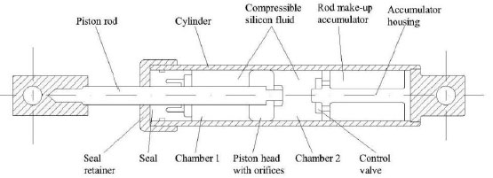
Section of a typical fluid viscous damper.
The kinetic energy of the piston is transformed in heat and dissipated across the cylinder. In order to evaluate the mechanical characteristics of a FVD, there are many tests to perform: cyclic tests at constant velocity to estimate the main damper characteristics for different values of velocity, different amplitude of displacement and different temperature; endurance test at constant cyclic velocity to evaluate the durability of the damper and the stability of its characteristics; sinusoidal cyclic tests to evaluate energy dissipation capacity; friction tests with a very slow force-control to evaluate friction resistance. In addition to these fundamental tests it is possible to perform a test with a seismic displacement input to evaluate the behaviour in a real case [20].
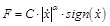
The mathematical model of a damper can be derived from the tests described above, obtaining a relationship between the force applied to the piston and the relative velocity between the piston and the cylinder; actually the most accepted law for these devices is:
 |
(1) |
where F is the damper force,
 is the velocity of the piston, C is a constant depending mainly by the annular orifice area, the diameter of the piston and the fluid properties as well as the temperature. It is possible to obtain a more stable device using different material for the piston and the cylinder, making it possible the different thermal dilatation of the two parts. Changing shape and dimension of the annular orifice provides the thermal effect counterbalance [17]; in Fig. (2) it’s possible to see the force-displacement curve for different value of C for a sinusoidal displacement history.
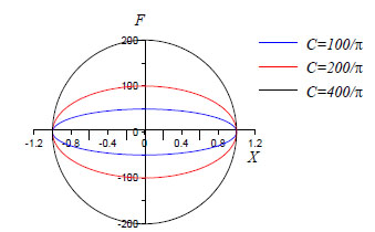
In Eq (1) α is a constant, whose values are generally in the range 0.15-1.95 and depends on the shape of the piston head; for civil applications it seems better that is not greater than 1. In theory with the same maximum displacement and maximum damper force it is possible to obtain a more energy dissipation with smaller values of α, as it is possible to deduce by Fig. (3); unfortunately this effect can create difficulty to the structure members because of the higher damper forces when the structure restoring forces are maximum.
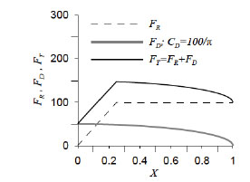
Hence, in order to obtain a major uncoupling between the elastic force and the damper force, a linear behaviour is preferable (α=1) [20]. Differently the damper force adds to the elastic one, increasing the stress in the structural members. Even if the restoring force and the damper one may be not enough uncoupled and stress on structural members can increase when some structural member yield early, as it is possible to see in Fig. (4), where FR is the elasto-plastic restoring force in a naked structure and FD is the damper force while FT is the sum of both.
In the last years new analytical model of the behaviour of FVD were formulated; e.g. in [21] it is proposed that the damper force depends not from the first derivate of the displacement, that is the velocity │
│, but from the fractional derivative of the displacement; the order of derivation is comprised between 0 and 1. This approach derives from the recent studies about visco-elasticity that use the fractional calculus to represent the behaviour of viscoelastic systems in general. However in this work the classical modelling approach is used.
Force-displacements curves for different values of C (α=1).
Force-displacements curves for different values of α.
Increasing of internal forces of an elasto-plastic single degree of freedom system with FVD.
3. ANALYSIS OF BUILDINGS WITH DAMPERS
In order to evaluate the benefits of introducing FVD in a structure, it is necessary to perform seismic analysis of the bare structure and of the structure equipped with dampers. Time history analysis assures reliable results both in the case of linear and non linear FVD; the analysis should take into account the eventual formation of plastic hinges in the structural members, that need to be modelled in their cyclic behaviour, even if the scope of introducing FVD is often to make possible that the structure does not experience any plasticization.
However it is possible to account the presence of FVD in structure also with simpler methods of analysis such as linear static analysis, linear dynamic analysis and non-linear static analysis (push-over).
Some code, such as US FEMA 356 and Italian NTC 2008, permits the use of linear and static analysis if the effects of FVD are taken into account.
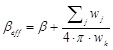
In FEMA 356 linear procedures are permitted if the structure remains linearly elastic for the selected earthquake hazard level, the effective damping does not exceed 30% of critical and some other conditions are satisfied. The code prescribes, for linear analysis, that the demand spectra will be scaled as a function of the effective damping, βeff, calculated as sum of natural damping of the structure and equivalent viscous damping generated by FVDs:
 |
(2) |
where β is the natural damping, wj is the work done by the j-th device in one complete cycle of the story displacement δj, wk is the maximum structural strain energy.
For linear dynamic procedures this correction must be done for each structural mode considered in the structural analysis.
The non-linear static procedure is corrected, respect to the cases without dampers, reducing the target displacement and the spectral acceleration utilising the effective damping βeff as defined above.
Finally, the non-linear dynamic procedure has no particular prescription for buildings with dampers, except that the substitution of viscous effects in energy dissipation devices by global structural damping is not permitted; as a consequence for this type of analysis the computational effort is much higher with respect as other types of analysis, but the results are surely more reliable and much less approximated.
In the Italian Code NTC 2008, there are no particular prescriptions for structures with FVDs; however it is possible to operate similarly to the FEMA 356, using, in case of linear analysis or non-linear static analysis, a coefficient η that enters in the response spectrum definition (as multiplier factor) and account for total damping:
 |
(3) |
in which ξ (which has the same significance of βeff) is the structural damping or the equivalent viscous damping. Also in this case, if the response spectrum analysis is selected there will be an η coefficient for each structural mode used in the procedure. If a time history analysis is performed the dampers must be included in the structural model.
It’s necessary to remark that linear procedures are approximated and it is not possible to obtain from them reliable results without a correction obtained by a comparison with other and less approximate analyses, like non-linear time history analyses; while FEMA 356 prescribes and suggests the above correction, Italian code does not give any prescription.
4. DESIGN OF FVDs: A PROCEDURE PROPOSAL
In this section a procedure to design FVDs for an existing structure is proposed. The procedure includes the evaluation of the efficacy of the dampers distribution by linear or non-linear analysis. This method of proceeding (that is by mean of the efficacy control after dampers design) is suggested in FEMA 356 (C2.3.2 - Systematic rehabilitation method). The preliminary project of the dampers can be performed with simple analyses, as linear analysis; the project of the dissipation system needs to know the number of FVDs, the dissipation coefficient C of the devices, the maximum velocities and the forces, and the maximum displacements that they experience.
For a SDOF system of mass m, stiffness K, ductility µ, strength R, the level of the associated elastic spectrum Se is given by:
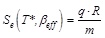 |
(4) |
where
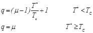
 |
(5) |
while q is the behaviour factor given in [22].
 |
(6) |
By solving Eq.(4) with respect to βeff and comparing this with the natural damping ratio β generally attributed to a system (β=0.05) it is possible to evaluate the quantity of damping βd to be introduced by the FVDs, that is
 |
(7) |
It is not reasonable increase the damping ratio over 60% because the improvement of the structural behaviour does not justify the major cost for the FVDs. This circumstance is visible in Fig. (5) in which is possible to see that an increase of the global damping ratio from 5 to 20% produce a force reduction higher than an increase from 20 to 65%:
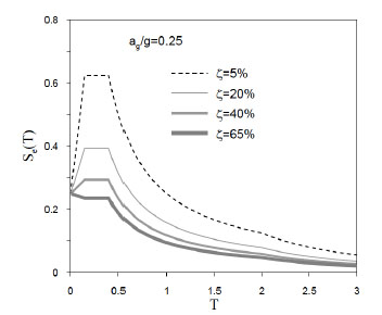
Response spectra for different values of global damping ratio.
The evaluation of the available capacity before the intervention and of the capacity demanded to the system thought indefinitely elastic, if a ductility level is hypothesized, can permit to define which is the convenient global damping ratio to obtain.
In order to provide a first estimation of the parameters needful to size FVDs to install in existing structures, it is possible to perform simplified analysis. It is hypothesized that the structure has a plane shear type behaviour (Fig. 6) and that the structural members are linear elastic.
If it is supposed to introduce at every floor only one equivalent FVD characterized by α=1, the equation that control the structure-FVD system with n degrees of freedom, subjected to the seismic ground acceleration

 |
(8) |
where M is the mass matrix,
 is the stiffness matrix,
 is the structural damping matrix,
 is the damping matrix of the devices and V is the influence vector which contain 1 in all his n components.
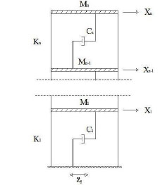
Simplified model for preliminary linear analysis.
If it is hypothesized that the dissipation capacity is constant along the stories and that if it is defined by the scalar C, the matrix
 becomes:
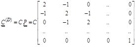 |
(9) |
Eq. (8) constitutes a group of n differential equations of second order that in nodal space are coupled. After determination of the eigenvectors of the non-damped system, it is hypothesized that only the first is effective, that is
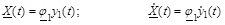 |
(10) |
in which ϕ is the eigenvector, associated to the circular frequency ω1, and y1(t) is the modal coordinate of the first mode of vibration. In modal space the equation of the motion becomes:
 |
(11) |
where, if the eigenvectors are normalized respect to the mass matrix, it holds
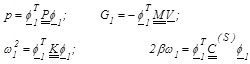 |
(12) |
In order to determine the solution of Eq. (11) it is necessary to fix the parameter C which is a measure of the energy that must be dissipated. It can be obtained first fixing the wanted equivalent damping ratio βeff. After, imposing that the structural damping ratio β is equal to 5% and
 . Finally it is possible to derive the parameter C in this way:
 |
(13) |
The parameter C obtained from Eq. (13), considering Eq.(9), represents the damping coefficient in one direction at each story. It contains information about damping coefficients CD of all dampers in a story.
If at a story a number r of devices and two dampers per device are hypothesized the damping force
 at the story is:
 |
(14) |
in which
 is the interstory velocity. In a classical disposition:
 |
(15) |
It’s manifestly that the higher the value of r and the lower the maximum damper force.
After the parameter C is determined, it’s possible to calculate, with usual analysis method, the solution of Eq. (11) and then the velocities and displacements of the dampers.
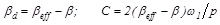
No damped structure (a). Damped structure (b).
5. APPLICATION
In this section it is explained how to apply the above strategy to a plain model. Further the benefits of the application of viscous dampers and the details of the design approach before explained are provided. The dynamic response of a structure subjected to a ground motion allowed to highlight the effective of the design solutions proposed and to identify potential and limits. First, the non linear response of a no damped system was observed and displacements at each story were recorded. After, viscous dampers were inserted by using steel diagonals (see Fig. 7) and the response was compared with the no damped configuration. Viscous dampers adopted for the simulation were first linear. Subsequently, non-linear force versus velocity behaviour was assigned and comparisons were repeated.
Reduction of the interstorey drift and base shear was evidenced.
5.1. Characteristics of the Model and Seismic Input
Two dimensional, five story moment frame r.c. structure is defined by rectangular cross section and infinity rigid storey. Diaphragm constraints were assigned at each of the five floor levels. The mass representing the weight at each floor level was assigned equal to 50 KN/m. For the damped configuration, steel diagonals were inserted allowing the connection of viscous dampers and floors.
Elastic modulus of the concrete Ec was assumed equal to 15000 MPa in order to take into account the concrete cracking of the elements.
The dampers were modelled using two-joint damper-type link elements. The geometry of the structure is reported in Fig. (7).
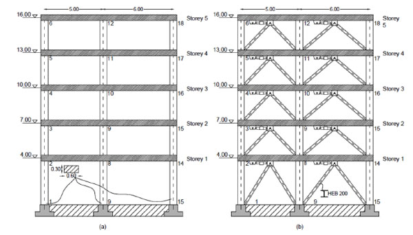
Two accelerograms of 30 seconds having PGA respectively 2.069 and 2.254 m/sec2 were used. These accelerograms resulted compatible with the code spectrum having the following characteristics:
|
ag=0.266 g, F0 =2.27, TC=0.422 s |
(16) |
where ag is the PGA, F 0 =[max (Se(T))]/a g, TC is the period that divides the constant acceleration branch from the constant velocity branch of the spectrum. In the following Fig. (8) the time history of the two accelerograms used in this application are shown. Further the response spectra are compared to the target spectrum.
Accelerograms and response spectra.
5.2. Structural Analysis
Modal analysis for the evaluation of the eigenvectors and the frequencies of the no damped system was performed. By adding to the damping ratio β (equal to 0.05 for the bare structure) the damping ratio βd it was possible to model the damping capacity of the dampers. Analyses with uniform and approximately triangular distribution of the capacity of the dampers at the five floors were performed.
Fast non linear analysis (FNA) that allows the study of the behaviour of the non linearity concentred in the non-linear links were carried out. The second order effects and the modification of stiffness provided by global deformation were neglected. At each integration step the stiffness matrix was assumed constant. Non linear components were computed by non linear force vector depending from LDR vectors (Load Dependent Ritz Vector).
5.3. Simulations and Test Results
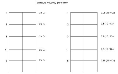
Modal analysis for the non-damped structure returned the first eigenvector ϕ1 and the correspondent frequency ω1. In details the first eigenvector, normalized with respect to the mass matrix, and the corresponding frequency, resulted
 |
(17) |
Three levels of structural strength R were fixed to which three values of the external dissipation damping corresponded in agreement to Eq.(4) (respectively βd=5%, βd=10% and β d=15%) under the hypothesis of ductility µ=1. Then the global damping coefficient of the dampers were evaluated by Eq.(13), that is
for βd =5% C1=110.55 kN sec/m
for βd =10% C2=221.08 kN sec/m
for βd =15% C3=331.62 kN sec/m
To this point different analyses were carried out varying the global dissipation capacity. For the comparisons the i-th analysis regarding the structure characterized by a global damping coefficient Cj was associated to the acronimous CjAi in agreement to Table 1.
Analyses carried out - linear behaviour of the dampers.
| ACCELEROGRAM | MODE | Equivalent DAMPING RATIO β [%] | DAMPING COEFF. C [kN sec/m] |
|
|---|---|---|---|---|
| UNIFORM DISTRIBUTION OF DAMPING α=1 |
ACC1 | No damp A1 | 5 | / |
| C1A1 | 5+5 | C1=110.55 | ||
| C2A1 | 5+10 | C2=221.08 | ||
| C3A1 | 5+15 | C3=331.62 | ||
| ACC2 | No damp A2 | 5 | / | |
| C1A2 | 5+5 | C1=110.55 | ||
| C2A2 | 5+10 | C2=221.08 | ||
| C3A2 | 5+15 | C3=331.62 | ||
| TRIANGULAR DISTRIBUTION OF DAMPING α =1 |
ACC1 | D1A1 | 5+5 | C1=110.55 |
| D2A1 | 5+10 | C2=221.08 | ||
| D3A1 | 5+15 | C3=331.62 | ||
| ACC2 | D1A2 | 5+5 | C1=110.55 | |
| D2A2 | 5+10 | C2=221.08 | ||
| D3A2 | 5+15 | C3=331.62 |
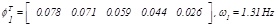
In Fig. (9) the variation of the interstorey drifts varying the external damping is shown. It is proved that doubling and tripling the external dissipation then amplitude of the response reduces respectively less than two times and three times. Namely, as above remembered, the increase of the external dissipation is progressively less effective and this suggest to limit external damping to 20%.
Maximum interstorey drifts for different levels of external damping.
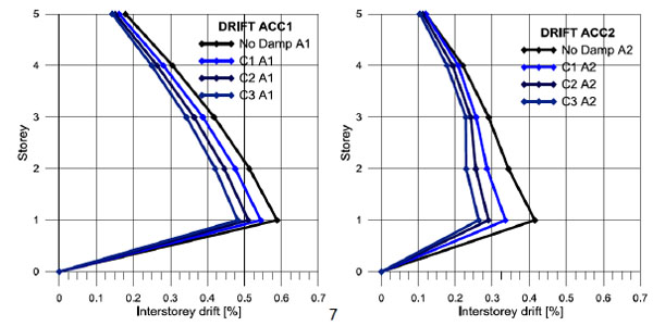
In Fig. (10) the time histories of the displacements at each storey are shown. It is evident the reduction of the displacement at the top of almost the 50 % for an external damping (βd=15%) three times greater than internal one.
Response time histories: a) structure without external damping; b) structure with external damping (βd=15%).
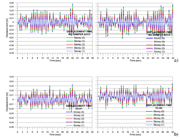
The analyses were repeated by using a triangular distribution of the dampers’ capacity along the height chosen in such a way to conserve the total nominal capacity of the dampers in the uniform distribution. In details if from Eq.(15) it derives that the total nominal dampers’capacity, say it
 , in a structure with n storeys is in the case of triangular distribution the dampers are distributed as in Fig. (11).
 |
(18) |
Distribution of dampers: a) uniform distribution; b) triangular distribution.
As it can be observed in Fig. (11) the sum of the products of the damper number by the damping coefficient of each damper is equal in the two types of distribution.
In order to remember the triangular distribution of the dissipation capacity the acronimous DjAi was used instead of CjAj (see Table 1) for each analysis.
In Fig. (12) it can be observed the greater efficiency of this type of distribution with respect to the uniform distribution of the external damping (Fig. 9) that suggests to prefer the triangular distribution associated to uniform one in agreement to the equivalence criteria explained by Fig. (11).
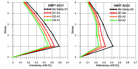
Maximum interstorey drifts for for different levels of external damping (α =1).
After the above mentioned simulations, non linear behaviour for the dampers was inserted in the triangular distribution. Specifically it was assumed α=0.15. The correspondent value for the storey damping coefficient
 was obtained by the following equivalence
 |
(19) |
where for
 two different assumptions were made: 1) maximum interstorey velocity and 2) average interstorey velocity.
The analyses were labelled as shown in Table 2.
Analyses with non linear behaviour of the dampers.
| Accelerogram | Damping Coeff. C | C derived by equivalence at maximum velocity | C derived by equivalence at average velocity | |
|---|---|---|---|---|
| TRIANGULAR DISTRIBUTION OF DAMPING α =0.15 |
ACC1 | C1 | SC1 A1 max | SC1 A1 med |
| C2 | SC2 A1 max | SC2 A1 med | ||
| C3 | SC3 A1 max | SC3 A1 med | ||
| ACC2 | C1 | SC1 A2 max | SC1 A2 med | |
| C2 | SC2 A2 max | SC2 A2 med | ||
| C3 | SC3 A2 max | SC3 A2 med |
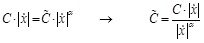
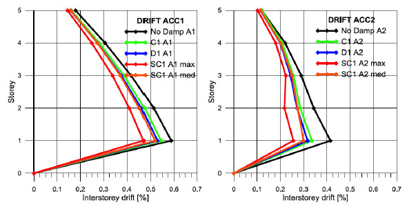
In the next figures a comparison is made between the case of linear behaviour and non linear behaviour of dampers. It is shown that when Eq.(19) is applied by using the average interstorey velocity there is the equivalence of results with the case of linear dampers, differently when Eq.(19) is applied by using the maximum interstorey velocity then a better efficiency is obtained. However it has not to be forgotten that this configuration produces a greater level of stress for the greater level of coupling between dampers and structure as shown in Figs. (13-15).
Comparisons between linear behaviour and non linear behaviour of the dampers. C1 capacity.
Comparisons between linear behaviour and non linear behaviour of the dampers. C2 capacity.
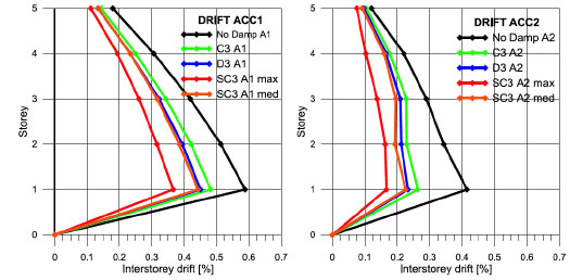
Comparisons between linear behaviour and non linear behaviour of the dampers. C3 capacity.
In order to show the difference between the case of linear and non linear dampers and between the different strategies of distribution of the dampers some time histories are inserted in the Figs. (16, 17).
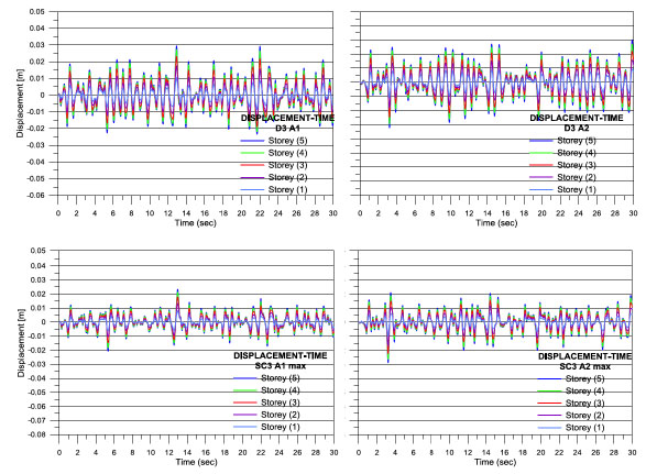
Time histories for C3 capacity: comparisons at each floor.
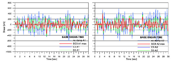
Base shear time histories for C3 capacity.
CONCLUSION
A criteria of design of linear viscous dampers has been proposed and discussed based on the hypothesis of uniform distribution of the damping capacity along the structure height. Then the effect of damping distributions different by the uniform one but equivalent to it in terms of overall damping capacity has been show by a practical application. Also, the effect of change of linear dampers in non linear ones (more often available in the practice) is observed. The study, applied to the case of structures with negligible ductility has highlighted that
- The design strategy proposed is effective producing a strong reduction of the structural deformation in the members where is most requested by a reduced level of the equivalent external damping (up to 15%) in agreement to the aims initially fixed;
- It is preferable to change the distribution of damping from uniform to triangular along the height in order to obtain the best results in terms of reduction of lateral displacements;
- The substitution of the linear dampers by non-linear ones evidences different effects depending on the criteria of equivalence used; in details the equivalence of the dissipating forces based on the average interstorey velocity produces an equivalence of effects in terms of lateral displacements, while the equivalence of the dissipating forces based on the maximum interstorey velocity produces a substantially decrease of the lateral displacements; however the use of non-linear dampers has to be carefully considered because of the degree of coupling that these devices have with a structure;
- An external equivalent damping equal to 15%, with the dampers’ distribution proposed, produces a 50% reduction of the displacements that is consistent with the request of demand reduction of many structures designed only for vertical loads and with a low level of ductility.
CONFLICT OF INTEREST
The authors confirm that this article content has no conflict of interest.
ACKNOWLEDGEMENTs
Declared none.

