All published articles of this journal are available on ScienceDirect.

The performance of Strengthened Lightweight RC Beams with different Techniques upon Exposure to Fire
Authors Info & Affiliations
Abstract
Introduction:
Reinforced concrete beams are used in a wide range of applications. In addition, reducing the weight of the concrete used increases the advantages of the beams. The main objective of this work is to study the performance of structurally strengthened lightweight reinforced concrete beams with different techniques with or without exposure to fire under concentric load and the efficacy of the fire protection system.
Methods:
The experimental specimens included eight half-scale tested rectangle beams with typical dimensions of 300 mm depth, 1700 mm total length, 150 mm total width, 50 mm cover, and 1500 mm span. The density of the lightweight polystyrene foam concrete was 1820kg/m3. The main parameters were fire resistance, different types of strengthening material for lightweight concrete beams, shape of the ferrocement layer on the lightweight concrete surface, and ferrocement thickness.
Results:
The results were analyzed in terms of crack patterns, failure modes, load deflection, load-strain behavior, stiffness, ductility, deformability, and absorbed energy.
Conclusion:
From the analysis of the results, the strength of LWC beams increased the strength and stiffness of the tested beam, and the fire protection system was found effective in protecting CFRP limitation from deterioration. In a theoretical study, the conservatism degree for calculating the maximum allowable flexure force was evaluated according to the ECP203, ACI-318, and BS-8110 codes.
1. INTRODUCTION
Concrete is the most popular construction material in the world due to its numerous advantages [1, 2], and it has also shown excellent fire performance [3-6]. Even though concrete has many advantages, one of the vital drawbacks of concrete is its high self-weight [7]. [Therefore, many research studies have been conducted to develop lightweight concrete. Lightweight concrete can be categorised as lightweight aggregate concrete and lightweight cellular concrete [8]. Lightweight concrete (LWC) has been used in buildings since the eighteenth century. However, it is essential to reduce the cost of reinforced concrete (RC) structures. The weight, type, and proportion of coarse and fine aggregates are the main methods used to reduce the density of concrete [18-21]. The lightweight cellular concrete can also be divided into two types: foamed concrete and autoclaved aerated concrete (AAC) (FC) [9]. Adding a foaming ingredient to the concrete mixture, which agitates the concrete with compressed air, produces foamed concrete [10, 11]. Owing to its low self-weight, thermal insulation, acoustic absorption, seismic resistance, extended lifespan due to fire resistance, weatherproof nature, workability, and material-saving capability, the potential usage of foamed concrete has expanded in the industry [11-17]. Hence, foamed concrete was used in this study. Results showed that the enhancement improved foam concrete's pore structure, increased strength, decreased water absorption, and marginally increased thermal conductivity [22]. This study examined how polyolefin fibre affected the compressive and flexural characteristics of foam concrete with densities ranging from 1300 to 1600 kg/m3 at relatively low volume fractions (0.0%, 0.20%, 0.40%, and 0.60%). The test study results showed that adding polyolefin fiber only slightly raised the compressive strength and flexural strength of foam concrete by 4.3% and 9.3%, respectively [23].
Fibre-reinforced polymers (FRPs) are rapidly being applied in civil engineering applications due to their benefits over conventional materials, such as high strength, lightweight, and corrosion resistance [24, 25]. The most popular uses are utilising epoxy resins to externally attach carbon fibre reinforced polymer (CFRP) laminates or sheets to reinforced concrete (RC), steel, or different elements [26]. Where fire resistance is not a critical design requirement, CFRP strengthening techniques are routinely used in bridge building. Although CFRP systems provide significant capability in buildings, their widespread application is hampered by concerns about their performance at elevated temperatures. Several researchers have recently identified the fire behaviour of FRPs as one of the top priorities in terms of critical research requirements [27, 28].
The aforementioned concerns are valid since, when subjected to temperatures between 300 and 500 0C, the organic matrix of FRPs decomposes and releases smoke, heat, soot, and harmful volatiles [29-32]. Moreover, at relatively increased temperatures, the strength, stiffness, and bond characteristics of FRPs are substantially degraded, notably when approaching the polymer matrix's glass transition temperature (Tg), which is generally in the range of 65-120 0C [31-33]. The bond between CFRP and concrete, which is critical to the performance of the strengthening systems, is also significantly reduced at temperatures over Tg. Bond property breakdown begins at temperatures lower than Tg in such cases. Structural fire damage or loss is a common unintended tragedy worldwide, causing hundreds of fatalities, injuries, and millions of dollars in property damage yearly [3, 7, 17]. The fire event has been classified as an incidental loading condition on the structure under the structural design code of practise. As a result, it is critical to design structures that can resist a fire situation for a specified amount of time [34, 35]. Fire is defined as a temperature fluctuation that occurs throughout time. Temperature time connections according to ISO 834 [36] are present in the equation, where T is the fire temperature, T0 is the ambient temperature, and t is the time in minutes.
T = 345 log10(8t + 1) + T0
Little information is available on the bond between externally bonded FRP systems and concrete at high temperatures. Single lap shear tests carried out by Gamage et al. [37, 38] demonstrated that when the temperature of epoxy bond raised over 60-70 °C, CFRP-strengthened concrete components gradually lost strength. Similar outcomes have been reported by Klamer et al. [39] based on a double lap shear test and a three-point bending test. Based on temperature measurements and numerical simulation, Gamage et al. [38, 40] recommended that vermiculite cement-based mortar thermal insulation can be used to increase the fire resistance of CFRP strengthening systems.
Studies on the performance of full-scale FRP-strengthened concrete members subjected to fire are also limited in the literature [41]. The conclusions of fire tests on FRP-reinforced RC beams [42-45] emphasise the need for proper fire protection systems and demonstrate the effectiveness of using thermal insulation to prolong the fire resistance of strengthened RC components. However, the reasons for degradation and the exact “critical” temperature beyond which the efficacy of FRP strengthening systems is lost are unclear. According to Kodur et al., there is a cautious lower constraint on the critical temperature for the Tg of bonding resin [46] currently utilised in the epoxy adhesives. The top limit might be as high as 250-300 oC if the FRP's structural performance is not needed to avoid collapse under the loads to be supported in the fire limit condition.
According to the literature, in order to leverage the mechanical contribution of FRP strengthening systems to RC members in a fire scenario, proper fire protection systems for building applications must be applied. However, there are currently no recommendations or valid thermomechanical models available for designing fire protection systems for FRP-strengthened RC members. In this regard, in addition to the heat transfer modelling work undertaken at Queen’s University [47, 48], a 3D thermal–structural model was developed by Hawileh et al. [49] and a very recent comprehensive model was presented by Ahmed and Kodur [50] but very little research has been done.
One of the major problems these days is the effect of fire on concrete structures, while there has been a rapid growth in using composite materials in engineering applications in the last few years. It was found that the use of lightweight aggregate concrete closely mimicked the response of normal-weight concrete and improved the behavior of RC elements at service loads. This lightweight concrete was made of expanded clay or volcanic cinder but not made of polystyrene foam. This has been the main impetus to carry out this study to fill this knowledge gap and provide information about this behavior. The effect of strengthening on LWC beam behaviour, fire resistance of LWC beam, and efficacy of the fire protection system was little investigated.
2. MATERIALS AND METHODS
2.1. Tested Specimens and Parameters
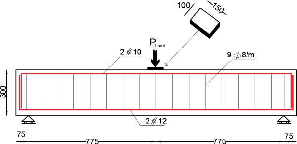
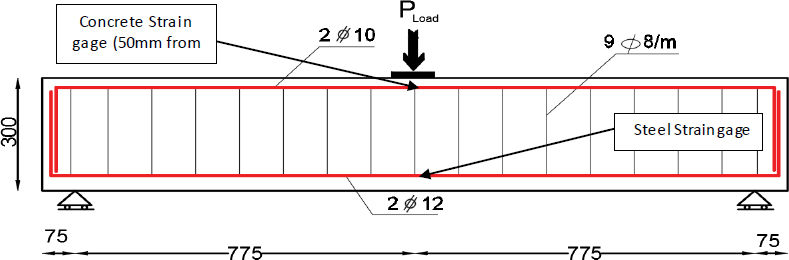
The performed experimental work included eight beams with typical dimensions, 300 mm of depth, 1700 mm of total length, 150 mm of total width, 50 mm of cover, and the clear span was equal to 1500 mm. The dimensions and reinforcement details of the specimen are in metric and shown in Fig. (1).
The parameters considered in this study are effects of fire on lightweight concrete beams, type of strengthening for lightweight concrete beams, effects of the shape of the ferrocement layer on the lightweight concrete surface, and ferrocement thickness of the protective CFRP layer when exposed to fire.
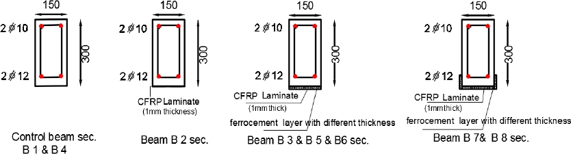
The eight tested specimens were divided into two groups as follows: Group one (G1): B1(NNC) control beam, B2(NSC) was strengthened by CFRP, and B3(NSCF) was strengthened by CFRP and ferrocement with a thickness of 20mm. Group two (G2): The beams were exposed to fire to reach 500°C for half an hour. Then, the beams were loaded with the ultimate load after cooling by air. It included a B4(FNC) control beam, B5(FSS-2) strengthened by CFRP and strip ferrocement with a thickness of 20mm, B6(FSS-4) strengthened by CFRP and strip ferrocement with a thickness of 40mm, B7(FSU-2) strengthened by CFRP and U-wrap ferrocement with a thickness of 20mm, and B8(FSU-4) strengthened by CFRP and U-wrap ferrocement with a thickness of 40mm, as shown in Table 1.
| Group | Specimens | Specimens code | Parameter | ||||
| Strengthening | Ferrocement Type | Heating Temp. °c | Thickness of Ferrocement (mm) | Shape of Ferrocement | |||
| G 1 | B1 | (NNC) | Non | ـــــــــ | Non | ـــــــــ | Non |
| B2 | (NSC) | CFRP | ـــــــــ | Non | ـــــــــ | Non | |
| B3 | (NSCF) | CFRP+Ferrocement | Calcium aluminate cement | Non | 20 | Strip | |
| G 2 | B4 | (FNC) | Non | ـــــــــ | 500 | ـــــــــ | Non |
| B5 | (FSS-2) | CFRP+Ferrocement | Foam+ Calcium aluminate cement | 500 | 20 | Strip | |
| B6 | (FSS-4) | CFRP+Ferrocement | Calcium aluminate cement | 500 | 40 | Strip | |
| B7 | (FSU-2) | CFRP+Ferrocement | Foam + Calcium aluminate cement | 500 | 20 | (U-wrap) | |
| B8 | (FSU-4) | CFRP+Ferrocement | Calcium aluminate cement | 500 | 40 | (U-wrap) | |
| Concrete Type | Cement(kg) | Sand(kg) | Coarse Aggregate(kg) | PolystyreneFoam(liter) | Water(liter) | Silica fume(kg) | Super-plasticizer(liter) | Polypropylene Fiber(kg) | Density(kg/m3) |
|---|---|---|---|---|---|---|---|---|---|
| LWC | 500 | 630 | 630 | 400.00 | 135 | 20 | 40 | 0.90 | 1845.7 |
2.2. Material Properties
All tested specimens were made from local materials. A type of plastic made from styrene is polystyrene foam. The concrete mix contained cellular foam, which is lightweight. Silica fume was added to the polystyrene foam, which has good moisture resistance and is immune to rot, mildew, and rust. Superplasticizer was employed to produce lightweight concrete that was workable.
High-strength concrete has been produced using silica fume. It is a product created when high-quality quartz is reduced to coal in electrical core furnaces to produce silicon. The fume released from the furnace is gathered and contains a lot of amorphous silicon dioxide and extremely small spherical particles. When measured using nitrogen adsorption techniques, silica fume is made up of very small vitreous particles with a surface area of about 20000 m2/kg. Silica fume reacts with lime during the hydration of cement to produce stable cementation compounds due to its extreme fineness and high silica content. Using silica fume as a component of the water-reducing admixture with a high range has become possible.
Superplasticizer works effectively to reduce the amount of water in the concrete mix. In order to fully hydrate the cement particles, it is mostly required to develop concrete. As per ASTM C494, 2001 of type V, the used super-commercial plasticizer is VISCOCONCRETE-3425.
The used polypropylene MasterFiber®012(BASF product) restricts the small crack formations that occur during plastic shrinkage and premature drying in order to provide hardened cementitious materials. They are implemented in concrete slabs, driveways, pavements, curbs, imprinted concrete, pipes, micro silica concrete, and thin section wallings. The length of these fibers is 19 mm at a rate of 0.7kg/m3 and tensile strength of 350N/mm2.
As presented in Table 2, the mixture included natural sand as the fine aggregate, fine crushed stone with a nominal maximum size of 10 mm as the coarse aggregate, fresh ordinary Portland cement, polypropylene fibre, and tap water. Polystyrene foam, silica fume, and superplasticizer were also added.
2.3. Preparation of Specimens
2.3.1. Casting and Curing
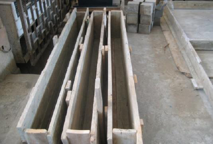
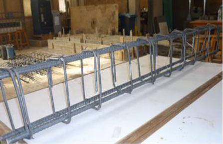
Wood forms were used to cast the beams at one time. These wood forms are shown in Fig. (2) and the reinforced bars are shown in Fig. (3). The strains of the main RFT were then placed in their position in the wood forms. Before casting the concrete, the wood forms were wet with water. Casting concrete occurred immediately after mixing. A mechanical vibrator was used to compact the concrete to ensure full compaction. After one day, the beams were removed from the wood form. The specimens were covered with sheets and sprinkled with water for a week, then left in the atmosphere of the laboratory until tested.
2.3.2. Strengthened by Beams
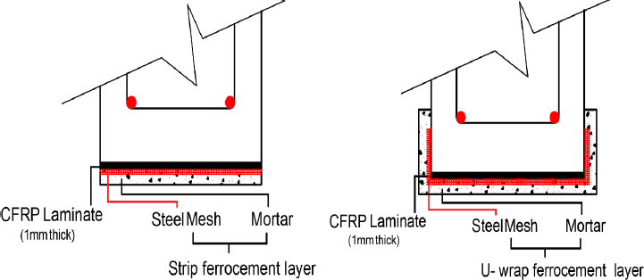
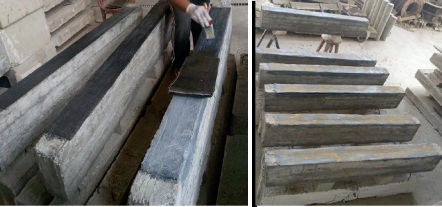
The tested beams were strengthened in two ways: by fixing CFRP to the bottom of beam, a layer of ferrocement was added to the bottom of beam, and by fixing CFRP and a layer of ferrocement to the bottom of beams with different thicknesses (20mm and 40mm), as shown in Fig. (4). The ferrocement layer has two types of strengthened shapes: the first is a strip shape, in which ferrocement is placed in the bottom of beams, and the second is a U-wrap shape, in which ferrocement is placed in the bottom and both sides (with 100 mm height) of a beam to strengthen it and protect it from fire flame.
2.3.3. Fire Protection Materials
The ferrocement mortar mix used in strengthened beams contained calcium aluminate cement. Two types of ferrocement mortar mix were used:
1- Ferrocement Mortar: Calcium aluminate cement and sand (passing through a 3.125 mm ASTM sieve). The mix proportions and water-cement ratio were selected as a water-cement ratio of 0.5 and 1:1.5, cement: fine aggregate.
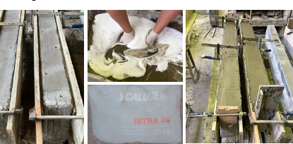
2- Foam Cement Mortar: Calcium aluminate cement, sand (passing through a 3.125 mm ASTM sieve), and liquid foam. The mix proportions and water-cement ratio were selected as a water-cement ratio of 0.5 and 1:1.5, cement: fine aggregate, as shown in Fig. (5).
Calcium aluminate cement (CAC) plays a significant role and can be a proper substitution for a fraction of the whole Portland cement volume. In situations requiring mortar or concrete to show specific properties (such as the need for quick hardening and resistance to chemical attacks, particularly acid attacks), using this cement is justified. Several aluminates with different volumes ranging from 40 to 90% make this cement [51]. At present, it has diverse applications in various areas. In this regard, it is used to provide insulation against heat and temperature variation [52], resistance against abrasion and scour in dam spillways and surface coatings [53], resistance against chemical attack (especially acid attack) [54], and ultrafast hardening of concretes.
Khaliq and Khan [55] explored the post-heating mechanical features of CACC (containing 70 Al2O3) and compared the postfire behaviors of this concrete and conventional concrete. It was reported that the alumina existing in the CACC considerably improved the mechanical features in comparison with conventional concrete. In this regard, the residual strength of the CACC was higher than that of the conventional concrete, especially for temperatures above 400 0C. It has been established that the mechanical features of this concrete are dependent upon the alumina content.
2.4. Test Setup and Instrumentation
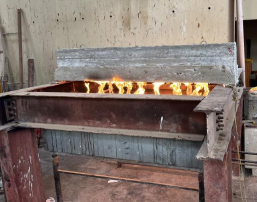
All tested beam specimens were supported on a special setup during firing and loading, as shown in Figs. (6 and 7). The setup for firing beams consisted of a steel frame formed of I-beams resting on four steel columns to support the beams during the firing. The furnace was constructed and prepared for this study with dimensions, such as 1500mm in width, 1500mm in length, and 1400mm in height. The fire flame system that was used consisted of two lines of gas pipes with 7-flame nozzles for each line.
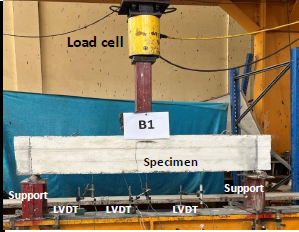
The span of the tested beams between supports was 1500 mm. The setup for loading beams consisted of a steel frame formed of I-beams acting as a lever. Two ends of the beam were attached to the strong floor of the laboratory using threaded steel rods, which provided a hinge support for the lever. The lever beam applied its reaction load in the center of the tested beam.
The vertical deflection of the tested beams was recorded using a dial gauge with an accuracy of 0.01 mm. Three dial gauges were used to measure the vertical deflection of the vertical load specimens. The position of the dial gauges at loading was 375mm from the lever and in the midspan of the beams tested specimens, as shown in Fig. (7).
HPM electrical strain gauges of 6 mm length and 120-Ohm resistance were used to measure the main steel strain. In this respect, one HPM electrical strain gauge was bonded to the bars in the appropriate locations of the bar (at the mid-span of the main steel), as shown in Fig. (8). Another strain gauge was used to measure the concrete beam strain. In this respect, one HPM electrical strain gauge was bonded to the concrete in the appropriate location of the concrete (at the mid-span of the beam under the load with a 50mm distance), as shown in Fig. (8). The load was applied step-by-step up to failure in a load-control manner. Strain gauge, LVDT, and load cell readings were recorded at each load increment using data logging equipment. At the end of each load, increment, observations, measurements, crack development, and propagation on the beam surface were recorded.
3. RESULTS
In this study, the tested reinforced concrete beams were regarded as lightweight concrete beams. The test results, the effect of strength, fire, and different types of strengths on the behavior of the tested beams were analyzed. The measured behavior is discussed in this section in terms of failure mode, load-deflection response, load-strain curves, stiffness, ductility, and absorbed energy, as shown in Table 3.
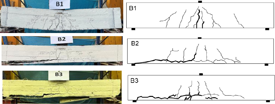
3.1. Crack Patterns and Modes of Failure
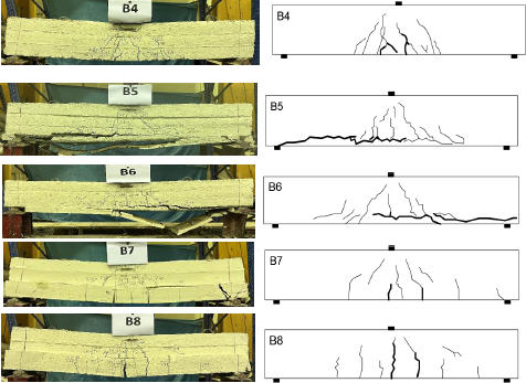
The crack patterns of the tested specimens and beams are shown in Figs. (9 and 10). In general, for LWC beams not exposed to fire, the crack pattern of the tested specimens is illustrated in Fig. (9). The crack width decreased, and the number of cracks at the tension zone near the main reinforcement decreased with strength. For LWC beams exposed to fire, the crack pattern of the tested specimens is illustrated in Fig. (10). The crack width decreased, and the number of cracks decreased to strengthen and protect CFRP with a ferrocement layer compared to the control beam. The strength of the tested specimens (B1(NN) and B4(FN)) was examined in groups G1 and G2. The number of cracks increased, and the crack width also increased due to exposing the tested specimens to fire.
Considering the crack pattern and failure modes for the tested specimens under fire in the group (G2), it can be concluded that the fire caused changes in the mode of failure and crack distribution and form. In addition, the strengthened U-wrap shape with a thickness of 2cm was more effective than the strengthened strip shape with a thickness of 2cm, and the strengthened strip shape with a thickness of 4cm was almost similar to the strengthened U-wrap shape with a thickness of 4cm.
3.2. Load-Deflection Curve
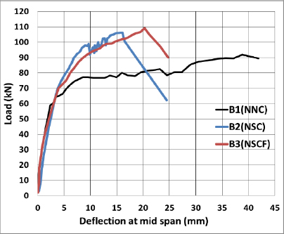
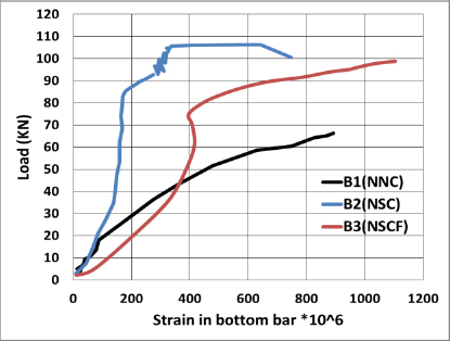
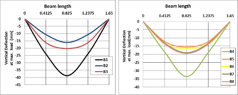
As shown in Fig. (11), the failure loads of tested specimens B1(NN), B2(NSC), and B3(NSCF) were 92kN, 106.26kN, and 109.14kN, respectively. The failure loads for the tested specimens B2(NSC) and B3(NSCF) increased by about 15.5% and 18.63%, respectively, by strengthening the beams compared to the control specimen. Moreover, the percentage decrease in deflection for B2(NSC) and B3(NSCF) by strengthening the beams compared to the control specimens was 58.5% and 47.79%, respectively. Strengthening beams significantly reduced the concrete compressive strain, as shown in Fig. (12).
| - | - | - | Parameter | Results | |||||||||||
| Group | Specimens | Specimenscode | Strengthened | Heating Temp. | Thickness of ferrocement (mm) | Shape of ferrocement | Cracking load(kN) | Δcr(mm) | Max. Load load(kN) | Δmax. (mm) | EA**(kN.mm) | Ductility | Yield stiffness | Initial stiffness | Cracks Number |
| G 1 | B1 | (NNC) | Non | Non | ـــــــــ | Non | 52.531 | 1.93 | 92 | 38.76 | 3282.8 | 11.03 | 68.56 | 87.71 | 14 |
| B2 | (NSC) | CFRP | Non | ـــــــــ | Non | 61.944 | 2.8 | 106.26 | 16.078 | 1346.2 | 3.74 | 80.63 | 86.99 | 9 | |
| B3 | (NSCF) | CFRP+Ferrocement | Non | 20 | strip | 69.954 | 3.91 | 109.14 | 20.233 | 2159.1 | 3.75 | 73.68 | 85.68 | 11 | |
| G 2 | B4 | (FNC) | Non | 500 | ــــــــ | Non | 56.871 | 2.12 | 72.89 | 33.58 | 2305.9 | 9.58 | 63.54 | 87.61 | 18 |
| B5 | (FSS-2) | CFRP+Ferrocement | 500 | 20 | strip | 56.871 | 4.18 | 105.198 | 16.176 | 1725.4 | 2.65 | 81.43 | 86.81 | 12 | |
| B6 | (FSS-4) | CFRP+Ferrocement | 500 | 40 | strip | 60.881 | 4.7 | 116.145 | 15.6 | 2430.4 | 2.17 | 76.9 | 83.24 | 12 | |
| B7 | (FSU-2) | CFRP+Ferrocement | 500 | 20 | (U-wrap) | 59.808 | 2.25 | 110.538 | 19.02 | 2205.2 | 4.07 | 78.7 | 87.77 | 14 | |
| B8 | (FSU-4) | CFRP+Ferrocement | 500 | 40 | (U-wrap) | 68.085 | 2.85 | 114.543 | 13.764 | 3169.5 | 3.63 | 79.27 | 87.16 | 13 | |
From this group, it can be concluded that the strength of tested specimens increased with use, and the strength for beams and deflection decreased.
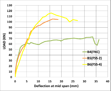
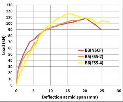
As shown in Fig. (13), the failure loads of tested specimens B4(FN), B5(FSCFS-2), and B6(FSCFS-4) were 72.89kN, 105.198kN, and116.145kN, respectively. The failure load for tested specimens B5(FSCFS-2) and B6(FSCFS-4) increased by about 44.32% and 59.39%, respectively, by strengthening compared to control specimen B4(FN). Moreover, the percentage decrease in deflection for B5(FSCFS-2) and B6(FSCFS-4) by strengthening the beams was 51.83% and 16.5%, respectively, compared to the control specimen B4(FN).
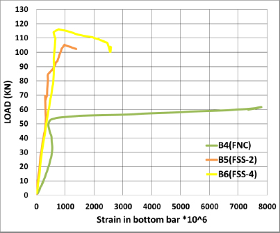
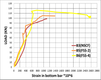
From this group, it can be concluded that the strength of the tested specimens increased with the increasing thickness of the ferrocement layer in beams. Strengthening beams significantly reduced the concrete compressive strain, as shown in Fig. (14).
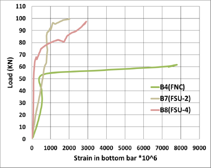
As shown in Fig. (15), the failure loads of tested specimens B4(FN), B7(FSCFU-2), and B8(FSCFU-4) were 72.89kN, 110.538kN, and 114.543kN, respectively. The failure loads for tested specimens B7(FSCFU-2) and B8(FSCFU-4) increased by about 51.7% and 57.15%, respectively, by strengthening the beams compared to control specimen B4(FN). Moreover, the percentage decrease in deflection for B7(FSCFU-2) and B8(FSCFU-4) by strengthening the beams was 43.36% and 59.01%, respectively, compared to control specimen B4(FN). The protection layer reduced the strain upon exposing the beam to fire, and the increase in protection layer thickness significantly reduced the concrete compressive strain, as shown in Fig. (16).
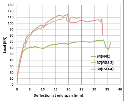
From this group, it can be concluded that the strength of the tested specimens increased with the increasing thickness of the ferrocement layer for beams.
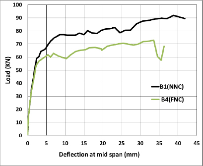
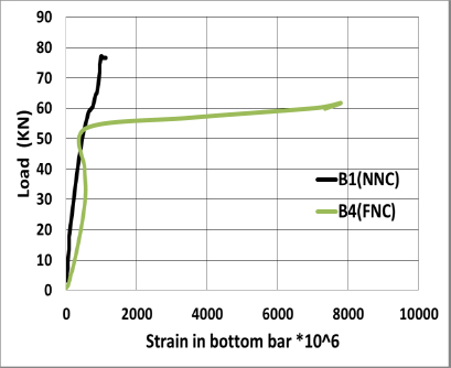
Comparing the case of the exposed control beam to fire, it was found that the failure loads decreased by about 26.263n of the change in the failure load and deflection i% when subjected to fire compared to control specimen B1(NN), as shown in Fig. (17). Moreover, the percentage increase in deflection for B4(FN) was 15.42% for specimens subjected to fire compared to specimen B1(NN). Fire beams significantly increased the concrete compressive strain, as shown in Fig. (18). The failure load for the tested specimens B5(FSCFS-2) decreased by about 3.7%, and B6(FSCFS-4) increased by about 6.42% when subjected to fire compared to B3(NSCF), as shown in Fig. (19). Moreover, the percentage decrease in deflection for B5 (FSCFS-2) was about 25.1%, and B6(FSCFS-4) increased about 38.58% compared to specimen B3(NSCF). Hence, it can be concluded that the fire flame affected the beam with a 2 cm ferrocement layer in B5(FSCFS-2); however, by increasing the ferrocement layer, the failure load increased in the case of B6(FSCFS-4) with a 4 cm ferrocement layer thickness. A protective layer reduced the strain on the exposed beam to fire, and an increase in the thickness of the protective layer significantly reduced the concrete compressive strain, as shown in Fig. (20).
This section summarizes that the layer of ferrocement can protect CFRP from fire flame and increase the strength of the beams. The strengthened U-wrap shape with a thickness of 2cm was found to be more effective than the strengthened strip shape with a thickness of 2cm, and the strengthened strip shape with a thickness of 4cm was more effective than the strengthened U-wrap shape with a thickness of 4cm (Fig. 21a and b).
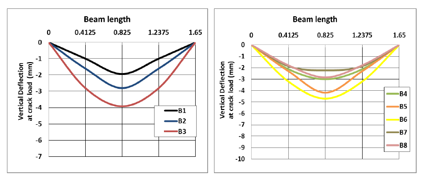
Comparing the change in the deflection with crack load, it was found that the deflection of test beams increased with strengthening, as shown in Fig. (21b). In the case of beams exposed to fire, the deflection at cracked load was found to be almost equal.
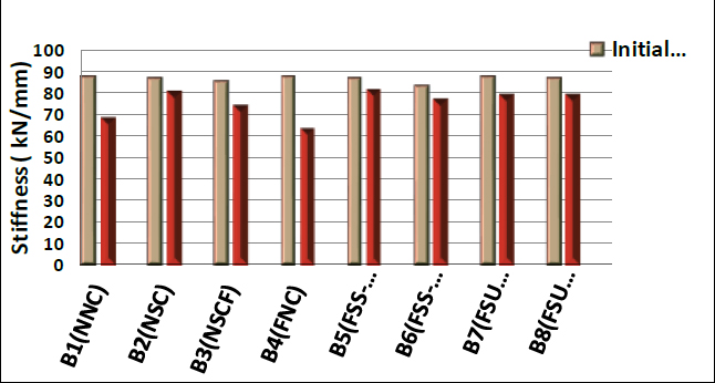
3.3. Stiffness
A beam’s stiffness indicates its ability to return to its original shape after an applied load is removed (ratio between the load to deflection). The initial stiffness is the slope of the load-deflection curve from the zero point until the cracking point. The yield stiffness is the slope of the load-deflection curve from the yield point until the ultimate point.
The behavior of beams was very similar in the uncracked elastic stage. In other words, the beams’ flexural stiffness was the same until the occurrence of cracks in the concrete. As shown in Fig. (22), in the cracked pre-yield stage, the stiffness of the beams was almost the same, slightly higher than that of the control beam; however, a significant decrease in beam stiffness was observed after the yielding of tensile steel, whereas by strengthening CFRP layers, the loss of beam stiffness was reduced. The CFRP layer decreased mid-span deflection and generally increased the stiffness for the same value of the applied load. Comparing B1 (NNC) and B4 (FNC), it was observed that fire could decrease the beam yield stiffness by 7.3%.
From the results of the tested beams B5 (FSS-2), B6 (FSS-4), B7 (FSU-2), and B8 (FSU-4), it was observed that using protection ferrocement during fire increased the beam yield stiffness.
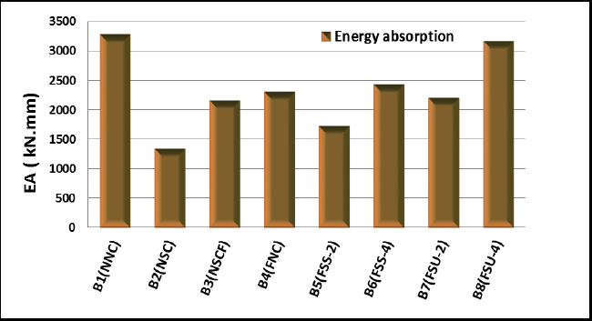
3.4. Energy Absorption
Energy absorption is defined as the area under a load-deflection curve. In general, the load-deflection curves in Figs. (11, 13, and 15) show that the energy absorption decreased by using a CFRP sheet layer. The fire affected the energy absorption in control beam B4 (FNC), but with increasing the thickness of a protective layer, the energy absorption also increased, as shown in Fig. (23).
| Specimens | Specimens Code | Δu | Δy | μE | Δf | Δmax | λ |
|---|---|---|---|---|---|---|---|
| B1 | (NNC) | 38.766 | 3.515 | 11.03 | 41.851 | 38.766 | 1.08 |
| B2 | (NSC) | 16.078 | 4.295 | 3.74 | 19.089 | 16.078 | 1.19 |
| B3 | (NSCF) | 20.234 | 5.392 | 3.75 | 24.72 | 20.234 | 1.22 |
| B4 | (FNC) | 33.534 | 1.98 | 9.58 | 35.25 | 33.534 | 1.05 |
| B5 | (FSS-2) | 16.176 | 6.102 | 2.65 | 18.505 | 16.176 | 1.144 |
| B6 | (FSS-4) | 15.558 | 7.14 | 2.17 | 23.248 | 15.558 | 1.50 |
| B7 | (FSU-2) | 19.026 | 4.68 | 4.07 | 24.237 | 19.026 | 1.27 |
| B8 | (FSU-4) | 19.494 | 5.376 | 3.63 | 23.85 | 19.494 | 1.22 |
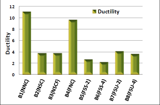
3.5. Ductility
The ductility of LWC beams is calculated as the ratio between the maximum deflection at the ultimate load and the deflection at the yield point (µ =Δu ⁄Δy). The yield point is the point at which the beam stiffness decreases until the ultimate point, as mentioned in Table 4.
The ductility decreased by exposing the beam to fire without protection by 29.7%.In the case of strengthened beams, the ductility decreased by 63%. It was observed that the CFRP sheet layer led to decreased mid-span deflection at the ultimate load, while the mid-span deflection at the yielding load was almost constant. Therefore, the CFRP sheet layer decreased the beam ductility, as shown in Fig.( 24).
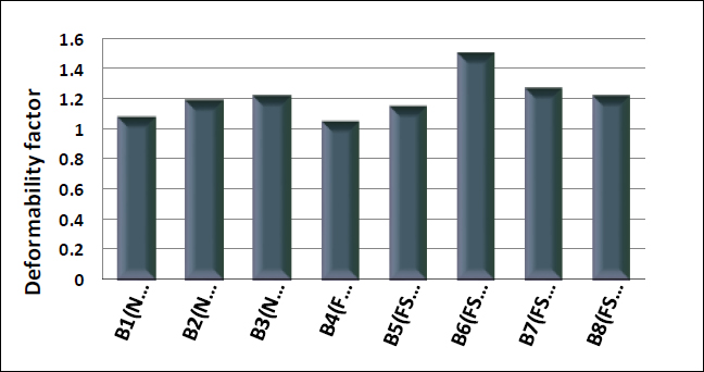
3.6. Deformability Factor
The deformability factor λ is defined as the displacement ratio at the ultimate load to displacement at maximum load. The ultimate load is equal to the load related to 85% of the maximum load on the decreasing part of load-deflection curve, as shown in Fig. (25). The equation can be formulated as:
λ = Δf / Δmax
4. DISCUSSION
This section compares the experimental and theoretical results using ACI-318, ECP203, and BS8110 to evaluate the proposal modification factors in polystyrene foam concrete. Finally, the proposed equation considers the effect of fire on LWC.
4.1. Evaluation of the Experimental Results According to Different Codes
The experimental results and analytical maximum forces due to ACI-318 [56], ECP203 [57], and BS8110 [58] can be compared using Eqs. 1-3, which are as follows:
 |
(1) |
 |
(2) |
 |
(3) |
β 1: the ratio of the depth of equivalent rectangular stress block to the depth of neutral axis.
ψf: is the FRP strength reduction factor as defined by ACI 440.2R-08 = 0.85.
C: the distance from the extreme compression fiber to the neutral axis at the ultimate capacity of the strengthened beam.
Ø : BS8110 LWC modification factor equal to 0.8.
λ : ACI318 LWC modification factor equal to 0.75.
For beams exposed to fire, the reduction factors for the compressive strength of concrete and yield strength of reinforcement steel at elevated temperatures according to ACI318 and BS8110 are mentioned in Table 5.
| Reduction Factor | LWC | |
|---|---|---|
| ACI318 | BS8110 | |
| Compressive strength of concrete | 0.95 | 1.0 |
| Yield strength of reinforcement steel | 0.6 | 0.6 |
| Group | Specimens | - | - | Heating Temp. | Thickness of Ferrocement (mm) | - | - | PECP203 (kN) | PACI318 (kN) | PBS8110 (kN) | PTest / PECP203 | PTest / PACI318 | PTest / PBS8110 |
| Specimens | Strengthened | ° C | Shape of Ferrocement | Ultimate Load | |||||||||
| Code | - | - | - | (kN) | |||||||||
| G 1 | B1 | (NNC) | Non | Non | ـــــــــ | Non | 92 | 56 | 44.3 | 49.6 | 1.64 | 2.1 | 1.9 |
| B2 | (NSC) | CFRP | Non | ـــــــــ | Non | 106.26 | 82.6 | 66.7 | 74.7 | 1.29 | 1.6 | 1.4 | |
| B3 | (NSCF) | CFRP+Ferro cement | Non | 20 | strip | 109.14 | 82.6 | 66.7 | 74.7 | 1.3 | 1.6 | 1.5 | |
| G 2 | B4 | (FNC) | Non | 500 | ـــــــــ | Non | 72.89 | 56 | 42.1 | 49.6 | 1.3 | 1.7 | 1.5 |
| B5 | (FSS-2) | CFRP+Ferro cement | 500 | 20 | strip | 105.198 | 82.6 | 63.4 | 74.7 | 1.27 | 1.7 | 1.4 | |
| B6 | (FSS-4) | CFRP+Ferro cement | 500 | 40 | strip | 116.145 | 82.6 | 63.4 | 74.7 | 1.41 | 1.8 | 1.6 | |
| B7 | (FSU-2) | CFRP+Ferro cement | 500 | 20 | (U-wrap) | 110.538 | 82.6 | 63.4 | 74.7 | 1.34 | 1.7 | 1.5 | |
| B8 | (FSU-4) | CFRP+Ferro cement | 500 | 40 | (U-wrap) | 114.543 | 82.6 | 63.4 | 74.7 | 1.4 | 1.8 | 1.5 |
| Correction Factor | PECP203 (kN) | PACI318 (kN) | PBS8110 (kN) |
|---|---|---|---|
| Fire | 1.35 | 1.65 | 1.55 |
| Non-fire | 1.3 | 1.6 | 1.5 |
Table 6 compares the experimental and analytical values of the experimental beams by different code values. The ratio between the experimental and analytical results [PTest / Pcode] decreased in strengthened beams compared to the unstrengthened beam and increased when strengthened beams were exposed to fire compared to the un-strengthened beam exposed to fire. From this, it can be concluded that correlation factors greater than unity are required for the modification factor of foam concrete. Moreover, the reduction factor of compressive strength during the fire must be less than unity for the tested specimens.
From these results, we can add a correction factor to the moment equation in the case of a protective CFRP layer with ferrocement and in the case of exposure to 500 0C. This correction factor is mentioned in Table 7.
CONCLUSION
The results of experimental and code prediction investigations into the fire performance of loaded intermediate scale LWC beam flexural strengthened with CFRP were discussed. Based on the results obtained, the following main conclusions can be drawn from this study:
Due to the protective materials, the CFRP strengthening system was able to maintain its effectiveness for a much longer amount of time while exposed to fire. This enhancement in fire endurance for thicker protection was made possible by a significant decrease in the temperature field, mainly at the concrete-CFRP interface.
Carbon fibre material bonded beams transformed the ductile flexural failure of the control beam into a brittle failure. Moreover, the ferrocement layer protected the CFRP layer from fire flame and increased the failure load of beams by an average of 52.7%.
For the unstrengthened LWC beams, the crack width increased, and the number of cracks also increased upon exposing the tested specimens to fire. For the unstrengthened LWC beams, the ultimate load decreased by being subjected to fire by an average of 26.263%, while the deflection increased by an average of 15.42%.
For strengthened LWC beams exposed to fire, the strengthened U-wrap shape with a thickness of 2cm was more effective than the strengthened strip shape with a thickness of 2cm, and the strengthened strip shape with a thickness of 4cm was almost the same as the strengthened U-wrap shape with a thickness of 4cm.
When exposed to fire, the ductility decreased by an average of 13.1% due to the decrease in the deflection corresponding to the maximum load, where the energy absorption capacity decreased by 29.7%. It was found that the fire affected the stiffness of the control beam, which was exposed to fire without strengthening, but by strengthening the beams with a ferrocement layer, the stiffness of the beams increased.
The deformability factor increased in strengthened LWC beams and decreased in the exposed beams to fire with a protective ferrocement layer. For strengthened LWC beams exposed to fire, the ultimate load increased by strengthening the beam by a different percentage according to the strengthening type. In the case of strip ferrocement layer protection with a 2cm thickness, the ultimate load increased by 44.32%, while the deflection decreased by an average of 51.83% and with a 4cm thickness, the ultimate load increased by 59.39% while the deflection decreased with an average of 16.5%.
In the case of U-wrap ferrocement layer protection with a 2cm thickness, the ultimate load increased by 51.7%, while the deflection decreased by an average of 43.36% and with a 4cm thickness, the ultimate load increased by 57.15% while the deflection decreased with average 59.01%.
Generally, the Egyptian code ECP203-2020 and the American code ACI 318-08 are more conservative than the results of British code BS 8110-97. The Egyptian code ECP203-2020 must consider LWC beams and the beams exposed to fire.
Protective ferrocement layer to protect CFRP should occur in different codes, and when calculating the theoretical flexural force in ECP203, ACI-318 and BS-8110 codes, the proposed correction factors of foam concrete can be equal to 1.3, 1.6 and 1.5, respectively, but in case of exposure to fire, the correction factor is equal to 1.35, 1.65, and 1.55, respectively.
One of the suggested indicators for improvement is to increase the percentage of calcium aluminate cement in the mix and paint the protection layer with polymeric materials that are resistant to fire and high temperatures.
LIST OF ABBREVIATIONS
| CFRP | = Carbon Fiber-Reinforced Plastic |
| CAC | = Calcium Aluminate Cement |
| LWC | = Lightweight Aggregate Concrete |
CONSENT FOR PUBLICATION
Not applicable.
FUNDING
None.
AVAILABILITY OF DATA AND MATERIALS
The data supporting the findings of the article is available in the [Sika Building trust] at [https://egy.sika.com/], reference number [SikaWrap®-230 C , Sika ViscoCrete®-3425 and The data supporting the findings of the article is available in the [master builders solutions] at [https://www.master-builders-solutions.com/en-us], reference number [MasterFiber®012 ]”.
CONFLICT OF INTEREST
The authors declare no conflict of interest, financial or otherwise.
ACKNOWLEDGEMENTS
The authors would like to thank all the members of the Reinforced Concrete Laboratory Staff, Faculty of Engineering, El-Mataria, Helwan University, for their help during the experimental work.

