All published articles of this journal are available on ScienceDirect.

The Design of a Real-Scale Steel Moment-Resisting Frame for Pseudo-Dynamic Earthquake Testing
Abstract
Background:
For the reliable prediction of the non-linear response of structures, severe seismic events have proven to be a challenging task. Although much non-linear analysis software exists, the accuracy of the results depends on the assumptions made in the characterization of the members. Typically, the analytical models are calibrated using experimental observations. With this scope, experimental research remains the most reliable mean for the assessment of the seismic performance of structures, and it is crucial to target the development of new analytical models and design methods.
Objective:
Quasi-static tests can provide information on the non-linear behaviour of subassemblies, but it is often difficult to relate the imposed force or displacement histories to those that might occur during an earthquake. The pseudo-dynamic method combines an on-line computer simulation with experimental information about the tested structure, providing the application of realistic dynamic response histories. In this paper, the preliminary analysis and the design of a pseudo-dynamic testing facility for the experimental study of a real scale two storeys-two bays steel MRF, with classical and innovative joint details, are shown.
Methods:
Pushover and Incremental Dynamic Analyses carried out with Seismostruct software estimate the forces and displacements expected at each storey for the selected ground motions. These analyses have been performed by varying the structural detail of the beam-to-column connections.
Results / Conclusion:
In this paper, the analytical prediction of the performance of two bays-two storeys steel frames equipped with different solutions of beam-to-column joints is focused. Based on the performed analyses, it has been recognized that steel frames with partial strength joints can provide satisfactory performance under severe seismic actions provided that the joints are adequately designed.
1. INTRODUCTION
The accuracy of the prediction of the non-linear response of steel structures, when subjected to severe seismic events, is a challenging task. The accuracy of non-linear software depends on the assumptions made in the characterization of members. Many of these analytical models are calibrated using experimental observations [1-4]. Therefore, experimental research remains the most reliable mean to assess seismic performance, and it is crucial for the development of new analytical models and design methods. Quasi-static testing can provide information on the non-linear behavior of members or sub-assemblies, but it is often difficult to relate the imposed force or displacement histories to those that might occur during an earthquake. These static methods are, therefore, primarily used to calibrate analytical models or to compare the relative performance of a variety of similar structural details. Shaking table tests can undoubtedly provide a realistic response, but size limitations often dictate the use of reduced scale structural models. Thus, although shaking table tests can provide real response data, physical limitations often necessitate the use of small, simple models of candidate structures. A way to overcome the deficiencies arising with conventional shaking tables tests is to execute Pseudo Dynamic tests. The method is virtually identical to traditional time-domain analysis except that rather than idealizing the non-linear stiffness characteristics of the specimen, the static restoring forces are measured as the experiment progresses. The PsD method is a hybrid testing method. It combines on-line computer simulation of the dynamic aspects of the problem with experimental information about the structure, acquired quasi-statically, to provide realistic dynamic response histories even for the non-linear behaviour of severely damaged structures. It uses mainly the same equipment as conventional quasi-static tests, in which prescribed histories of loads or displacements are imposed on specimen structures through hydraulic actuators. Nowadays, a lot of experimental reports regarding the seismic behavior of the traditional and innovative beam-to-column joints are available. However, how the local behavior of such connections influences the overall response of frames under seismic loading conditions is not experimentally determined.
Consequently, there are some uncertainties in the range of validity of the modeling approaches commonly adopted for non-linear time-history analyses. The numerical models widely adopted have limitations because of the limited availability of full-scale experimental data [5-9]. To investigate this issue, a comprehensive experimental program is currently ongoing at the STRENGTH Laboratory (STructural ENGineering Testing Hall) of the University of Salerno. The experimental work is based on the testing of steel connections of both traditional and innovative types in MRFs. In detail, the facility is constituted by a real scale two storeys-two bays steel Moment Resisting Frame (MRF) tested by varying the beam-to-column connections [9-11]. The MRFs are designed according to a collapse mechanism of global type, having been designed through the Theory of Plastic Mechanism Control [12]. This rigorous procedure is based on the kinematic theorem of plastic collapse, assuring a collapse mechanism of the global type where plastic hinges develop at the beam ends and in the column bases.
To design the testing facility, both non-linear static and dynamic analyses with the computer software SeismoStruct [13] have been performed. These analyses have allowed to assess the actions that the actuators transmit during the tests. Both IDA and pushover analyses have been performed [14-19]. When pushover analyses have been considered, according to Eurocode 8 [20], two different distributions of horizontal forces have been adopted: 1) the modal force distribution, 2) the uniform force distribution. The results of the pushover analyses have been compared with those deriving from the IDA. Finally, the ability of the structures to self-center has also been assessed. In this work, the preliminary analysis and the design of a testing facility under development are presented.
2. EXPERIMENTAL PROGRAMME
To apply a loading history corresponding to an earthquake action, the specimen must be subjected to Pseudo Dynamic tests. This testing method combines a computer simulation of the dynamic problem with the experimental response. In particular, inertia and viscous forces are simulated, starting from the definition of the mass and viscous damping matrix. Differently, the displacements are calculated, solving the equation of motion step-by-step during the test. The PsD method has several advantages. In fact, with this experimental method, it is possible to obtain results similar to dynamic tests without the weight and size limitations associated with the use of shaking tables. The technique also allows to monitor more easily what happens during the test since the time of application of the displacements is relatively slow. Additionally, being a quasi-static test, the required equipment is simple (Fig. 1 ).
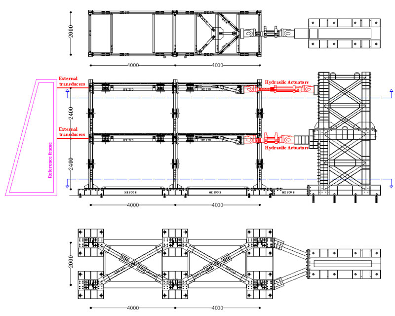
To test a real scale two storeys-two bays steel MRFs, the design of the geometrical and mechanical properties of the steel frames results strongly conditioned by the actual size of the Laboratory and by the equipment available. In the considered case, to govern the two available dynamic degrees of freedom, two different MTS hydraulic actuators have been adopted.
The first actuator is an MTS 243.45-01 (maximum load capacity of 649 kN in compression and 445 kN in tension and a piston stroke of ± 1066 mm) which will be used to apply, under displacement control, the axial load at the first storey; the second actuator is an MTS 243.60-02 (load capacity of 648 kN in both tension and compression and a piston stroke of ± 508 mm) which will be used to apply, under displacement control, the axial load at the second storey.
The two actuators will be fixed to a rigid steel braced frame acting as a reaction wall. The column bases will be bolted to a rigid support and anchored to the strong laboratory floor through high strength dywidag bars (Fig.1).
To measure the external displacements, two MTS transducers Temposonic - Series R will be used. Finally, LVDT transducers will be utilized to acquire local measures of displacements and deformations.
The beam-to-column connections employed in the tested frames have been designed [9-11], as required by Eurocode 3 Part 1-8 [21], according to the component method by appropriately identifying the element of the joint where the dissipation occurs and providing to that element a lower plastic threshold. Such a technique is based on the definition of non-linear spring representative of the joint components. The method is suitable for the modeling of any kind of joint provided that the components are correctly identified, and their constitutive law is accurately modeled.
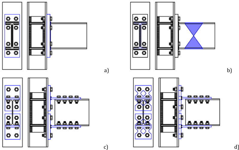
In particular, four types of connections have been designed and tested:
2.1. EEP-CYC 02
A partial strength extended end-plate joint with end-plate in bending as the weakest joint component (Fig.2a). This joint was designed to investigate the energy dissipation capacity and the ductility of a classical extended end-plate connection [22-27];
2.2. EEP-DB-CYC 03
A full-strength extended end-plate joint designed forcing the development of plastic hinge in the beam by cutting the beam flanges according to the design criteria for the reduced beam section (RBS) strategy as suggested in a study [28-39] (Fig.2b). In this case, the analysis is aimed at investigating the energy dissipation capacity of the RBS which is the weakest joint component;
2.3. TS-CYC 04
A partial strength joint with a couple of T-stubs bolted to the beam flanges and to the column flanges, designed to be the primary source of plastic deformation capacity (Fig.2c). The design goal is to avoid the plastic engagement of the components related to the column web panel, i.e., the column web in tension and column in compression and the panel zone in shear [40-43];
2.4. TSJ-XS-CYC 07
A partial strength joint with a couple of dissipative T-stubs, with an hourglass shape, bolted to the beam flanges, and to the column flanges, designed to be the only source of plastic deformation capacity (Fig.2d) [11].
The experimental program provides for the execution of a further four pseudo-dynamic tests performed on a two-story single-span frame made with HE 200 B column made of S355 steel and an IPE 270 beam in S275 steel class and a steel-concrete composed slab. The steel grade of the designed frame members is selected to develop a mechanism of the global type. As shown in Fig. (1), the clear length of the spans is L= 4.00m; the clear height of the storeys is h=2.40m. The testing involves cases where the seismic energy is dissipated at the end of the beams. Therefore, splices are provided on both sides of the beams so that the repair of the frame after the tests can be done efficiently. Since the designed MRF provides a collapse mechanism of global type, plastic hinges at the column bases are expected; therefore, column splices are also used in this case. This solution is adopted in order to reduce the cost and time related to the stages of disassembly and assembly of the different frame solutions (Fig.1).
3. BEAM-TO-COLUMN JOINT BEHAVIOUR
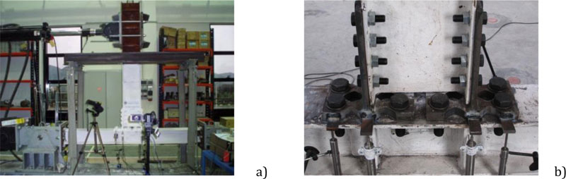
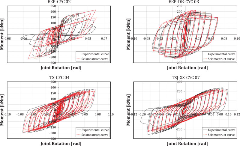
The behavior of the joint typologies considered in this study has been experimentally analyzed in previous works of the same authors [9-11]. The experimental tests confirm the reliability of the design procedure of the joints. In fact, according to the design purposes, all the designed joints are characterized by similar resistance and initial stiffness even though they are realized with different philosophies. In Fig. (4a) the envelopes of the cyclic moment-resisting curves obtained through experimental tests on the joint sub-assemblage depicted in Fig. (3a) are given for the four joint typologies. In particular, the experimental layout in case of the joint tests is composed by two different actuators: an MTS 243.60 actuator, operating under force control, with maximum loading capacity equal to 1000 kN in compression and 667 kN in tension and maximum piston stroke equal to +/- 126mm and an MTS 243.35 actuator with maximum load capacity equal to 245 kN and piston stroke equal to +/- 508mm.
During the tests, the bottom actuator has been governed under force control, imposing a constant axial compression force in the column equal to 650 kN. Conversely, the top actuator has been connected to the end of the beam to apply the cyclic displacement history (Fig. 3a). In particular, the tests have been carried out according to the procedure for the pre-qualification of beam-to-column joints suggested by AISC-358 provisions [44].
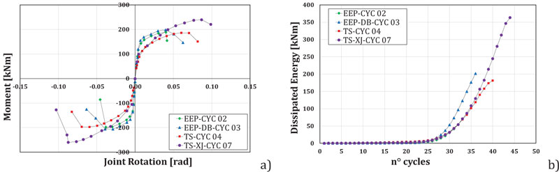
In Fig. (4a), the experimental response of the connections in terms of joints rotation vs. flexural moment has been reported. In particular, the beam-to-column joint rotational behavior has been evaluated starting from the displacements measured at the top of the beam, in correspondence of the load application, subtracting the elastic part due to the beam and to the column flexural deformability. It can be observed that the widest envelope characterizes the joint EEP-DB-CYC 03 up to joint rotation equal to about 0.04 rad but the other typologies of joint, such as in particular TSJ-XS-CYC 07 with dissipative T-stubs, depicted in Fig. (3b) can dissipate the same or higher amount of energy due to their more significant ductility, as shown in Fig. (4b).
4. INELASTIC STATIC ANALYSES OF STEEL FRAMES
To evaluate the seismic behavior of steel frames equipped with the typologies of joints previously described, static and dynamic inelastic analyses have been developed.
The beam-to-column connections have been modelled adopting link elements that connect two nodes initially coincident. The response curves of the links are linear and symmetrical for all degrees of freedom, except for in-plane moment-rotation of the frame. This moment-rotation curve has been implemented with a smooth model whose parameters have been calibrated on the experimental curves (Fig. 5) and reported in Table 1 [45].
The gravity loads have been modelled as equivalent concentrated forces applied in correspondence of the connection of the transversal beam to the IPE270 beam. Distributed loads equal to 7.00 kN/m2 and 9.50 kN/m2 have been considered at the first and second storey, respectively.
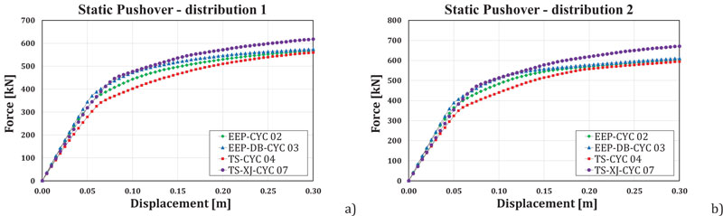
According to Eurocode 8, each frame has been submitted to two static inelastic analyses characterized by two different shapes of the horizontal force distributions: 1) modal force distribution; 2) uniform force distribution. In Fig.(6), the response of the analysed models is represented. In Fig. (7), the results of the pushover analyses of the four frames are described.
It can be observed that even though the four joint typologies are very different, the scatters between the performances provided by the different joint typologies are moderate, evidencing a satisfactory behavior also of the steel frames with partial strength joints. Such differences are very low in terms of maximum base shear, as shown in Table 2.
Also, it can be observed that, due to the large ductility of the partial strength joints, especially of the X-shaped double split tee joints, frames with partial strength joints can provide satisfactory performances.
5. DYNAMIC NON-LINEAR ANALYSES OF STEEL FRAMES
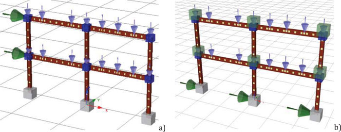
Incremental dynamic non-linear analyses have been performed on the four steel frames with the different typologies of joints. The seismic masses corresponding to the distributed loads and the weight of the beam and column profiles have been modelled as concentred in the beam-to-column intersection (Fig.6b). Each frame has been submitted to dynamic analyses progressively increasing the peak ground acceleration up to the achievement of a plastic rotation at the base of the column equal to 0.045 rad.
|
Joint typology Smooth parameters |
EEP - CYC 02 | EEP - DB - CYC 03 | TS - CYC 04 | TSJ – XS - CYC 07 |
|---|---|---|---|---|
| Initial flexural rigidity [EI] | 41411.00 | 47238.74 | 200000 | 54530.09 |
| Cracking moment [PCP]/ [PCN] | 116.46/-130.07 | 140.00/-140.00 | 185.00/-190.00 | 236.69/-236.69 |
| Yield moment [PYP]/ [PYN] | 157.00/-173.00 | 190.00/-200.00 | 190.00/-200.00 | 473.38/-476.38 |
| Yield curvature [UYP]/ [UYN] | 0.01/-0.01 | 0.013/-0.017 | 0.022/-0.022 | 0.148/-0.148 |
| Ultimate curvature [UUP]/ [UUN] | 0.10/-0.10 | 0.20/-0.20 | 0.40/-0.40 | 0.30/-0.30 |
| Post yield flexural stiffness as a % of elastic EI3P [+/-] | 0.0307/0.0352 | 1.00/-0.01 | 2.50/-5.50 | 0.014/-0.014 |
| Stiffness degrading parameter [HC] | 4.00 | 10.00 | 200.00 | 16.80 |
| Ductility-based strength decay parameter [HDB] | 0.05 | 0.50 | 0.30 | 0.38 |
| Hysteretic Energy-based strength decay parameter [HBE] | 0.15 | 0.01 | 0.35 | 0.52 |
| Smoothness parameter for elastic-yield transition [NTRANS] | 1.00 | 1.00 | 1.00 | 0.023 |
| Parameter for shape of unloading [ETA] | 0.50 | 0.50 | 0.50 | 0.30 |
| Slip length parameter [HSR] | 0.25 | 0.25 | 0.38 | 1.10 |
| Slip sharpness parameter [HSS] | 0.03 | 10.00 | 0.20 | 0.30 |
| Parameter for mean moment level of slip [HSM] | 0.50 | 1.00 | 0.45 | 1.27 |
| Exponent of gap closing spring [NGAP] | 8.00 | 0.20 | 0.20 | 16.98 |
| Gap closing curvature parameter [PHIGAP] | 3.00 | 0.20 | 0.20 | 0.023 |
| Gap closing stiffness coefficient [STIFFGAP] | 5.00 | 0.20 | 0.20 | 1.85 |
| Frame typology | Base Shear [kN] | |
|---|---|---|
| Horizontal Force distribution type 1 (modal distribution) | Horizontal Force distribution type 2 (uniform distribution) | |
| Frame with EEP - CYC 02 joints | 537.69 | 575.14 |
| Frame with EEP - DB - CYC 03 joints | 575.14 | 583.75 |
| Frame with TS - CYC 04 joints | 520.30 | 564.80 |
| Frame with TSJ – XS - CYC 07 joints | 581.12 | 629.20 |
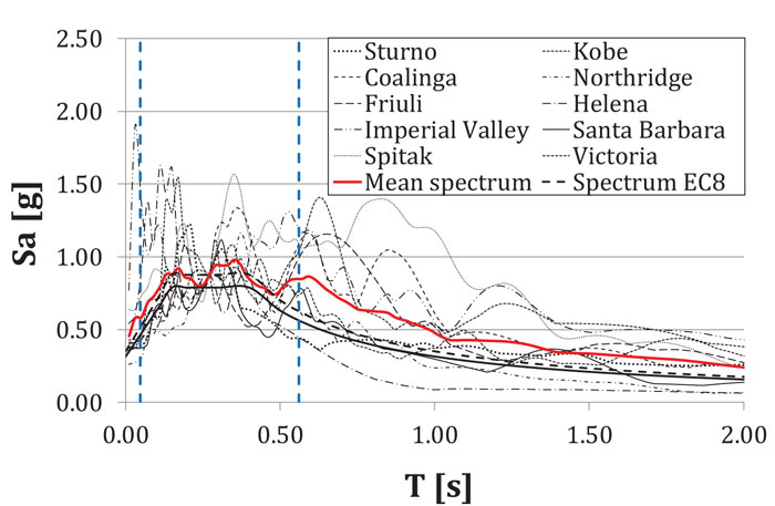
A set constituted by ten ground motion records has been considered, and the IDA has been performed increasing the spectral acceleration progressively up to the achievement of the experimental value of the plastic rotation supply. The choice of the set of accelerograms is not accidental [46-48]: only the seismic events whose average spectrum is compatible with the design spectrum given by Eurocode 8 for the soil type A have been considered [20]. All accelerograms have been scaled according to the design spectrum in correspondence of the average value of the fundamental periods of the structure given in Table 3.
Table 3.
| Frame typology | T [sec] |
|---|---|
| Frame with EEP - CYC 02 joints | 0.262 |
| Frame with EEP - DB - CYC 03 joints | 0.260 |
| Frame with TS - CYC 04 joints | 0.280 |
| Frame with TSJ – XS - CYC 07 joints | 0.276 |
In Fig.(8), the elastic spectrum of the analysed earthquakes, the design spectrum given by Eurocode 8, and the average spectrum have been reported.
If the first mode of vibration governs the structural response, its variability will be equal to zero because the structure, for each accelerogram, will be subjected exactly to the spectral acceleration corresponding to the first period of vibration. Conversely, since the response of the structure is influenced by the higher modes and for higher values of the spectral acceleration, the structure is more deformed and less stiffened, the vibration period is larger, and the correspondent acceleration is different for each selected accelerogram. In terms of record-to-record variability, these are the main factors that influence the response of the structures.
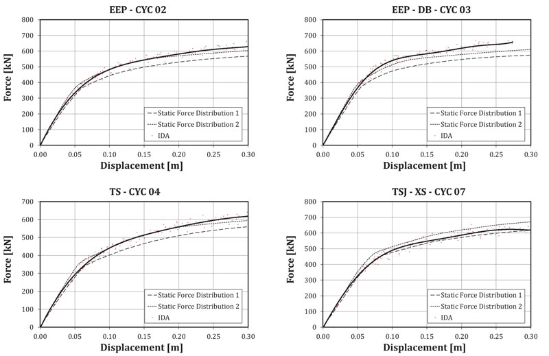
For each frame, the maximum value of the base shear provided by the IDA has been assessed. The regression curve of all the results provided by the ten accelerograms has been evaluated, as depicted in Fig. (9). In the same figure, for each frame, also the force-displacement curves provided by the static inelastic analyses are given.
It can be observed that the results of the IDA, for low values of the displacements, are in a good agreement with the curves of the static inelastic analyses performed with a modal distribution of the horizontal forces.
On the contrary, for high values of the displacements, they are sufficiently close to the curves of the static inelastic analyses performed with a uniform distribution of the horizontal forces. In Fig. (10), the comparisons between the IDA curves for the four frames are represented. The IDA confirmed the results provided by the static inelastic analyses.
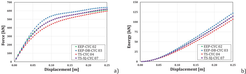
Also, in this case, it can be observed that, even though in terms of energy dissipation, the solution providing the best response is the dog-bone, partial strength joints can give a satisfactory performance provided that they are adequately designed. Especially, the solution with dissipative double split tee joints appears attractive. In fact, this solution offers a high energy dissipation of the seismic input energy (Fig.9b).
6. SELF-CENTERING CAPACITY OF THE STEEL FRAMES
To evaluate the self-centring capacity of the analyzed structure, the global lateral displacements due to imperfections have been compared with the residual deformation of the structure at the end of the simulated seismic events. The geometrical imperfections can be evaluated according to Eurocode 3 Part 1-1 [49] as:
where Øo is the basic value to Øo = 1/200;
αh is the reduction factor for height h applicable to columns:
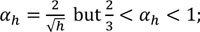
h is the height of the structures in meters;
αm is the reduction factor for the number of columns in a row:αm =
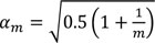
m is the number of column in a row including only those columns which carry a vertical load not less than 50% of the average value of the column in the vertical plane considered.
In the analyzed case, with an inter-storey height h equal to 2.40m and m equal to 2, αh = αm = 1 and, consequently, Ø = 0.005. The vertical interstorey displacements due to the geometrical imperfections are:
 |
The residual deformation of the structure after a severe earthquake, for each frame typology and each accelerogram, have been assessed performing non-linear dynamic analyses with intensities leading to the achievement of a plastic base rotation equal to 0.045 rad.
In Table 4, the average values of the residual displacements of the frames evaluated for the ten accelerograms are reported.
Since the residual displacements were always higher than the reference inter-storey drifts due to the geometrical imperfections, the structures, in all cases, did not self-center. However, the frame with dissipative double split tee joints was characterized by the best performance in terms of residual deformations.
| Frame typology | Residual interstorey displacements [mm] | |
|---|---|---|
| First Storey | Second Storey | |
| Frame with EEP - CYC 02 joints | 43.74 | 19.95 |
| Frame with EEP - DB - CYC 03 joints | 56.28 | 11.59 |
| Frame with TS - CYC 04 joints | 42.07 | 35.02 |
| Frame with TSJ – XS - CYC 07 joints | 26.06 | 16.15 |
CONCLUSION
The present work belongs to a broader theoretical and experimental program aimed to verify, through pseudo-dynamic tests on 3D two bays-two storeys steel frames equipped with different joint typologies, the actual possibility to design seismic resistant steel frames with partial strength joints.
Within this framework, starting from the experimental results on different solutions of beam-to-column joints characterized by the same resistance and initial stiffness, the attention, in this paper, has been focused on the analytical prediction of the performances of two bays-two storeys steel frames equipped with the above different solution of beam-to-column joints. Specifically, four steel frames with full strength and partial strength joints have been preliminary designed and successively analyzed through non-linear static and dynamic analyses.
On the basis of the preliminary results obtained, the main conclusions are the following:
- Steel frames with partial strength joints can provide excellent performances under severe seismic actions provided that the joints are adequately designed.
- Both non-linear static and incremental dynamic analyses evidence that even though the joints solution, in terms of energy dissipation, providing the best response is the dog-bone, partial strength joints can give satisfactory performance.
- The incremental dynamic analyses evidenced that the frame with X-shaped Double Split Tee joints can dissipate a significant amount of energy, and it is characterized by a considerable capacity to re-center the structure after a severe earthquake.
CONSENT FOR PUBLICATION
Not applicable.
AVAILABILITY OF DATA AND MATERIALS
Not applicable.
FUNDING
None.
CONFLICT OF INTEREST
The author declares no conflict of interest, financial or otherwise.
ACKNOWLEDGEMENTS
Declared none.

