All published articles of this journal are available on ScienceDirect.

Flexural Capacity of Steel Rack Connections Via The Component Method
Abstract
Background:
In pallet rack structures, cold-formed steel (CFS) beams and columns are connected through dry joints, so beams can be easily disconnected according to changes of the rack geometric layout. Due to the great variety of connector types and member geometries, recent design codes recommend experimental tests on rack connections to assess their mechanical features. Nevertheless, tests only allow for the overall response of a joint to be evaluated, without providing information about the contribution of each component of the joint to its stiffness and strength.
Objective:
In this paper, a mechanical model is developed in order to provide useful information about the structural behaviour of rack beam-column connections.
Methods:
The proposed mechanical model is based on the application of the Component Method (CM) and it allows for the flexural resistance of steel rack connections to be analytically assessed. Analytical results are compared with experimental data from tests performed at the Structures and Materials Testing Laboratory of the Department of Civil and Environmental Engineering of Florence.
Results:
Results show a good agreement with experimental data, highlighting the accuracy of the proposed approach. The mechanical model allows for the weakest component of the joint and its failure mode to be evaluated, and it highlights the importance of an adequate welding between the beam-end section and the connector.
Conclusion:
The mechanical model provides fundamental information about the influence of structural details on the overall behavior of rack joints, it appears as a complementary method to expensive experimental tests and it can be used to improve the design of rack connections with the goal to increase their structural response.
1. INTRODUCTION
The behavior of beam-column joints has a great influence on the structural response of frame structures, especially in the context of the performance-based seismic design of steel storage pallet racks, as several researches have highlighted [1-3].
The influence of the behavior and modeling of beam-column joints and thin-walled cold-formed steel (CFS) members on the overall structural response of steel rack structures has been evaluated through both experimental tests and numerical studies [4-8]. To assess the mechanical behavior of beam-column joints, several methods can be used: experimental tests, empirical models, numerical models and mechanical models [9].
The most accurate knowledge of the joint behavior is provided by experimental tests. Bending moment-rotation laws of full-scale rack connections have been investigated in several experimental tests according to the single and/or double test cantilever method [10-13]. The drawback is that this technique is too expensive for everyday design practice, and it does not give information about the influence of each connection’s component to the overall structural response of joints in terms of stiffness and strength [14].
Empirical models of rack connections are based on empirical formulations obtained through regression analyses of experimental data [15]. Unfortunately, these models are only applicable to joints whose features are like those used to generate the empirical formulations. Based on previous observations, an approach applicable to all types of beam-column joints and capable to evaluate their main features is required. Finite Element (FE) models and mechanical models based on the use of the Component Method (CM) fulfil this requirement.
FE numerical models may predict the behavior of beam-column joints. They are used to evaluate the influence of various parameters on the overall performance of connections, to overcome the lack of experimental results, and to generate parametric studies. In [16] three-dimensional non-linear FE numerical models of rack connections are developed providing suitable results. The influence of the column structural response on the moment-curvature law has been analyzed in [17], whereas effects of mechanical and geometrical characteristics of tabs and the beam have been investigated in [18]. These numerical models represent the most suitable tool to evaluate the response of a joint. The drawback of the numerical approach is due to the large data set required for calibration and the time-consuming.
Vice-versa, the designer needs a method that starting from the geometrical characteristics of the connection allows for its main structural features to be obtained and then used through simplified F.E. numerical models in analyses of whole frame structures. Based on these considerations, to give a preliminary evaluation of the ultimate bending moment of rack connections and to identify their weakest component, in this paper a mechanical model, which utilizes the CM [9, 19-21], is proposed. This model describes the joint through a combination of rigid and flexible springs, which are modelled by means of stiffness and resistance values evaluated from elastic structural analysis and empirical tests. Results are in good agreement with those of an experimental campaign [22] carried out at the Structures and Materials Testing Laboratory (SMTL) of the Department of Civil and Environmental Engineering of Florence.
2. EXPERIMENTAL TESTS
2.1. Features of Rack Connections
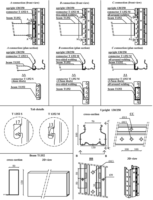
To assess the structural behavior of rack beam-column joints, three full-scale connections (in the following A, B and C, (Fig. 1), manufactured by the same company, have been tested using the cantilever test method [23].
Each connection has the same beam, with a hollow rectangular cross section (height/width/thickness = 130/50/2 mm), and the same upright (column), with a perforated open section (height/width/thickness = 100/130/2.5 mm), to accept connector’s tabs.
The A connection has a four-tab connector (named T 1352 S, 4 mm thick), which is obtained directly from the beam by folding its end. B and C connections are both characterized by a five-tab connector (named T 1352 M, 3.5 mm thick), but they differ from one another because of the welding used to join the connector to the beam-end section.
In B connection, the connector is welded to the beam-end by means of a double-sided welding; in the C type, the connector is welded all-around the beam-end section.
Fig. (1) shows geometric details of tested connections, with nominal values of their dimensions. Steel members, used in experimental tests, fulfilled geometrical tolerances provided by [24]; nominal values of their geometrical features have been used in the application of the CM.
Following steel grades are used for members and connections: S350GD (fyk=350N/mm2) for uprights and beams, and S235JR (fyk=235N/mm2) for welded connectors. For each connection three tension coupons have been tested [25]; mean yielding and ultimate stresses are summarized in Table (1).
| Member | Mean Yielding Stress [N/mm2] | Mean Ultimate Stress [N/mm2] |
|---|---|---|
| Column | fy,cw - 415 | fu,cw - 461 |
| Connector | fy,co - 282 | fu,co - 366 |
| Beam | fy,b - 451 | fu,b - 474 |
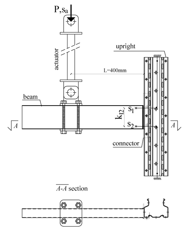
In all tests the load P is applied to the beam at a distance L = 400 mm from the external face of the column Fig. (2) [23]. P is then increased until the connection fails.
The load P has been measured through a load cell, and the vertical component of the displacement
sa at the loaded section has been monitored by the linear variable displacement transducer (LVDT) of the testing machine. Wire-actuated encoders (s1 – s2) have been inserted and connected to a computer assisted data-logging system, together with the load cell.
The rotation of the connection has been observed and a plot of the bending moment M and the rotation Ѳ has been drawn, with: M = L P and θ = θcd - θce where:  is the total rotation of the connector-end and
  is the elastic rotation of the column according to [12] with: hc the height of the column, E the elastic modulus of steel, Jc the inertia moment of the column, s1 and s2 displacements measured by wire-actuated encoders placed on top and bottom of the beam-end section, and k12 their relative distance.
2.2. Experimental Results
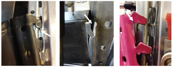
The ultimate bending moment is greater in B and C connections than in A connection. The difference is mainly due to the greater number of tabs in T 1352 M connector, which gives a longer lever arm. The connection failure is related to the failure of the welding in B connection and to the failure of tabs in C connection. Vice versa, in A connection, the collapse is due to the punching of the column web at slots Fig. (3).
The comprehensive results of tests, included any sensor used, deformation modes, failure mechanisms and ultimate moment capacity of tested connections, are provided in [22].
3. THE COMPONENT METHOD APPLIED TO RACK CONNECTIONS
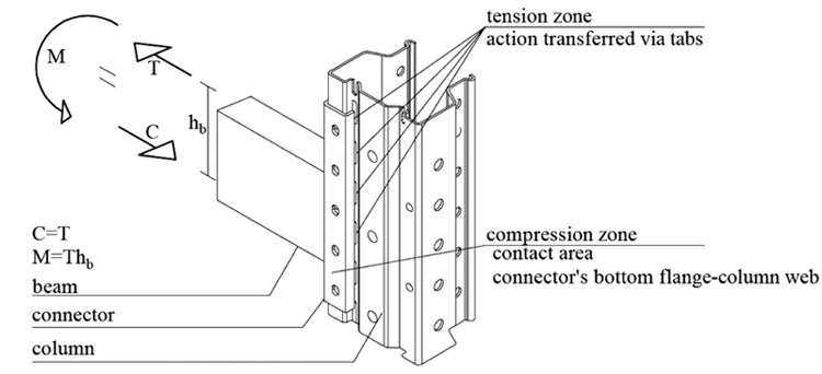
A mechanical model is developed with the aim to evaluate the flexural strength of rack connections and their failure mode, without the need to perform experimental tests. The assessment of mechanical features of rack connections is obtained through an analytical approach based on the application of the component method. In the CM, the joint is considered as an assembly of individual basic components whose identification, evaluation and assembly are the most important steps. Regarding the load transfer path, in the cantilever test method, the load is applied to the beam, which in turn transfers a shear and a moment to the connector and then to the upright via: tabs in the tension zone, and through the contact between connector’s bottom flange and the column web in the compression zone Fig. (4).
In studied joints, the following three components can be identified: the welding between the beam-end section and the connector (3.1 section) and, at connector’s tabs, tabs in shear (3.2 section) and the column web in punching (3.3 section).
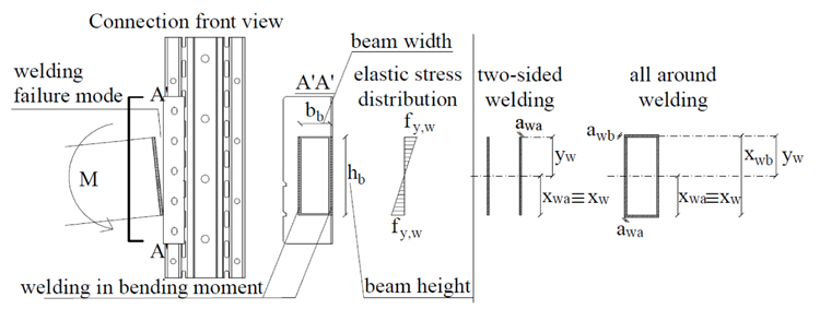
3.1. Welding
The welding connects the beam-end section to the connector (B and C connections). Its ultimate strength can be obtained through equation (1), assuming an elastic distribution of stresses and the welding failure when the yielding stress is reached in the extreme fiber Fig. (5):
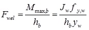 |
(1) |
where:
Mmax,b is the maximum bending moment transferred by the beam;
hb is the height of the beam;
yw is the distance between the welding center of area and the welding upper extreme fiber;
fy,w is the welding yielding tensile stress equal to fy,co;
Jw is the inertia moment of the welding.
In particular Jw is given by following equations:
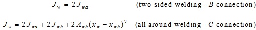 |
with:
 |
where:
awa and awb are the effective throat thickness of vertical and horizontal welds respectively;
bb is the width of the beam;
xw is the distance of the welding center of area from the beam bottom flange.
3.2. Tabs in Shear
Tabs transfer forces from the connector to the column in the tension zone.
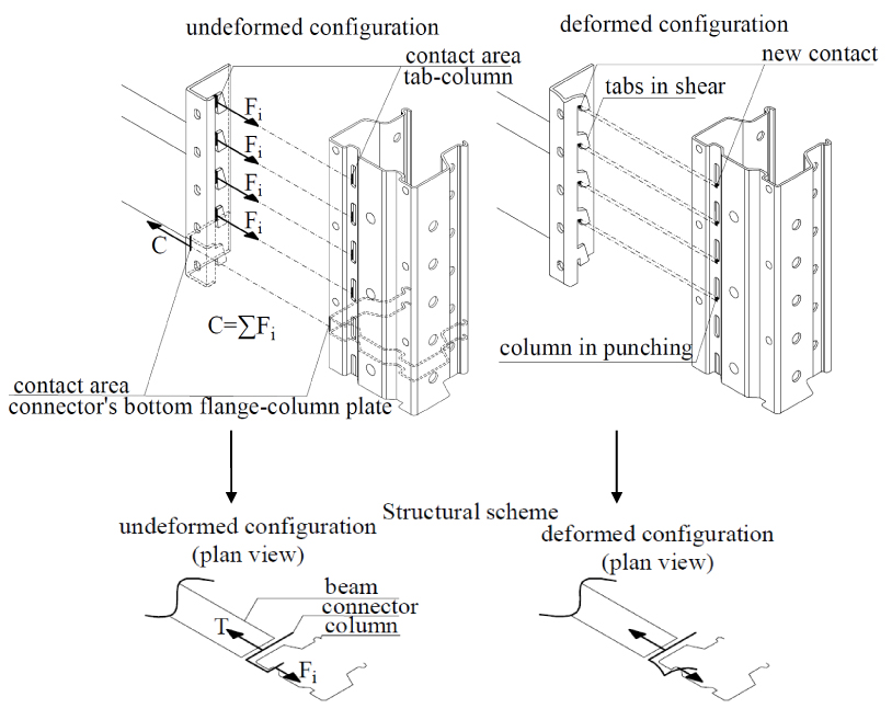
After an initial deformation of the connector due to the load exerted by the column wall Fig. (6), tabs are in shear and they fail in shear; the shear resistance (2) is:
 |
(2) |
with:
fu,co is the ultimate stress of connector’s steel;
Av,tab=ltabttab is the shear area of the tab Fig. (7), where ttab is the tab’s thickness (4mm for T1352 S connector and 3.5mm for T 1352 M, see Fig. (1)) and ltab is the tab’s length (17mm for T1352 S connector and 13mm for T 1352 M, see Fig. (1)).
3.3. Column Web in Punching
In the deformed configuration, the column web at the level of holes is in punching because of the contact with tabs Fig. (8). The resistance of this mechanism can be obtained through equation (3) according to [19], considering the analogy with bolted connections:
 |
(3) |
where:
tcw is the thickness of column;
fu,cw is the ultimate tensile stress of column;
dm=2htab+ttab is the perimeter of the tab in contact with the column web Fig. (8) (htab = 6mm for each connection type, Fig. (1)).
3.4. Mechanical Model
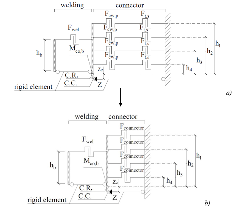
The mechanical model to predict the connection flexural resistance is shown in Fig. (9a). It refers to B and C connections, whose connector has five tabs.
Spring representing the behavior of the welding is located at the level of the beam upper flange; those representing tabs and the column in punching are placed at the level of tabs.
The center of rotation (C.R.) is assumed at the level of the beam bottom flange. The ultimate moment of the connection is described assuming the plastic distribution of internal forces. The compression force is transferred by the contact between the connector bottom flange and the upright web.
The flexural resistance of the connector (Mco,b) protruding over the flange surface of the beam cannot be exceeded, then, the distance (zc) of the center of compression (C.C.) from the center of rotation (C.R.), can be determined by the equation (4):
 |
(4) |
where: C is the reaction force in the compression zone, equal to the sum of forces in the tension zone.
Finally, the ultimate bending moment of the connection Mu,num can be predicted by the equation (5):
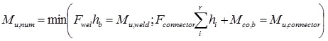 |
(5) |
where: Mu,weld is the ultimate bending moment of the welding; Mu,connector is the ultimate bending moment of the connector; hi is the distance of i tension component (i=1:4) from the centre of rotation and Fconnector=min(Fcw,p; Ft,s) Fig. (9b).
3.5. Comparison of Results
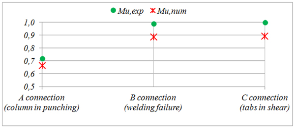
Non-dimensional values of the ultimate moment with the CM (Mu,num), and the average of experimental values 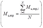 , with N=2 the number of tests for each connection and Mu,exp,i the value of ultimate moment in i-test, [22] are shown in Fig. (10). The percentage differences between (Mu,num) and (Mu,exp), the standard deviation
 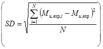 of experimental results and the connection failure mode are listed in Table (2).
Results show the high level of accuracy of the proposed mechanical model, although with reference to a low number of tests. The proposed mechanical model underestimates the experimental flexural resistance by 10% and allows the failure mode of the joint, which depends on its weakest component, to be predicted.
Fig. (11) shows non-dimensional values of ultimate moments of all three connection types.
| Connection type | (Mu,num-Mu,exp)/Mu,exp | SD | Failure mode |
|---|---|---|---|
| A | -8% | 7.5 | Punching of column |
| B | -10% | 2 | Welding failure |
| C | -10% | 5.5 | Tabs in shear |
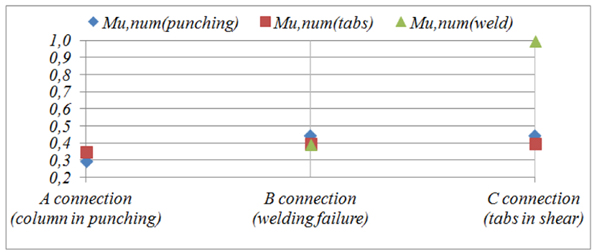
Results clearly highlight the importance of an adequate welding. When the welding is extended all-around the beam-end section, the connection failure is associated to the collapse of tabs (Mu,num(tabs) – C connection, see Fig. (11)), with a higher ultimate moment and ductility [22], otherwise the connection failure mode is due to the welding failure (Munum(weld) – B connection, two-sided welding). Although it involves an increase in production costs for rack manufacturer, an all-around welding is recommended. If dimensions of tabs are increased (ttab and ltab, and then the tab’s shear area Av,tab (2)), the weakest component of the connection becomes the column web in punching (Munum(punching)-A connection, see Fig. (11).
CONCLUSION
A mechanical model is proposed to evaluate the ultimate bending moment of rack connections and to identify the collapse mechanism of each component. Results agree with those obtained in an experimental campaign carried out at the Structures and Materials Testing Laboratory of the Department of Civil and Environmental Engineering of Florence and they highlight the accuracy of the proposed method and mechanical models developed to calculate the ultimate strength of the connection components.
The mechanical model can be used for an assessment of rack joints and it appears as a complementary method to expensive experimental testing required by standard codes. Moreover, the proposed method, evaluating the weakest component of the connections, can be used to provide adequate design chancing with the goal to increase the carrying capacity of rack joints. Observing that rack structures are produced in long series, the proposed method can represent an effective benefit in the context of an economical optimization of industrial rack structures.
Further investigations on the assessment of the initial stiffness of rack connection by using the CM are suggested with the aim to give a preliminary evaluation of the moment-rotation curve of rack joints. At the same time, a reliability analysis of rack joints would be useful to evaluate the influence on the structural response of joints due to the variation of the material properties and geometrical uncertainties.
CONSENT FOR PUBLICATION
Not applicable.
CONFLICT OF INTEREST
The authors declare no conflict of interest, financial or otherwise.
ACKNOWLEDGEMENTS
The authors wish to thank Rosss SpA (Italian Rack Manufacturing Company, Scarperia e San Piero, FI, Italy) and especially the president S. Bettini and the engineer G. Lavacchini, who have supported this research. Moreover, the authors greatly appreciate the skillful work of Mr. S. Giordano, Mr. F. Bruni and Mr. E. Barlacchi of the SMTL of the Department of Civil and Environmental Engineering of Florence for their assistance in the experimental work.

