All published articles of this journal are available on ScienceDirect.

Assessment of the Peak Response of a 5MW HAWT Under Combined Wind and Seismic Induced Loads
Abstract
Background and Objective:
The rapid growth of the wind energy industry has brought the construction of large-scale wind turbines with the aim of increasing their performance and profits to areas characterized by high seismic hazard. Previous research demonstrated the seismic vulnerability of large-scale wind turbines when seismic and wind actions are considered simultaneously in the demand model. In this study, the response of the supporting structure of a land-based horizontal axis wind turbine under the combined effects induced by wind and earthquake is presented.
Method:
Using a decoupled approach, numerical simulations of the wind and seismic loads effects are performed separately using a specific model for the aerodynamic damping and then joined. Both simulations are done using free open-source software that are FAST simulating the aerodynamic response of the rotor and OpenSees simulating the dynamic behaviour of the tower. The fitted generalized extreme value distributions of the multi-hazard peak response in terms of base moment and shear, total drift, and top rotation are calculated for different seismic and wind load intensities by means of Monte Carlo simulations. The analyses are referred to the specific case study of a land-based wind generator.
Results and Conclusion:
The maximum demand is associated with the operational rated scenario and for high values of the peak ground acceleration, only the parked condition leads to larger values of the response if compared to others. The analyses showed that it is essential to consider the combined seismic and wind actions in the demand model to derive a complete multi-risk analysis of the land-based structures.
1. INTRODUCTION
The seismic response of Horizontal Axis Wind Turbines (HAWTs) has recently attracted growing interest, since the wind energy industry has increased its size worldwide. The increase in the performance and profits from wind energy requires the increase of the size of rotor diameter and hub height since the power produced is proportional to the third power of wind speed as well as the square of rotor radius. Therefore, the increase of the mass of the Rotor-Nacelle Assembly (RNA) induces larger tower base moment demand, due to the combined effect of wind and seismic loads. Consequently, the multi-megawatt HAWTs have become very slender structures heavily loaded on top and characterized by a long period, whereby the seismic load effects may govern their structural design.
In response to these new trends and design challenges, several researchers have investigated different aspects of the implications that seismic loads have considering wind turbine design and assessment. The first numerical investigations carried out by Bazeos et al. [1], and Lavassas et al. [2] were focused on the tower support structure. In particular, detailed Finite Element (FE) models of the tower with the RNA mass lumped at the top were developed to investigate the tower stresses and potential stress concentration/buckling scenarios. As a result, they stated that seismic design might become crucial if wind generators are installed in regions with higher seismic hazard and soft soil conditions. Moreover, Bazeos et al. [1] also presented a comparative analysis of the dynamic response, using models of different complexity: full shell-element, beam column, and s-DoF.
In a more recent paper, Witcher [3] used models that explicitly simulated the rotor along with the turbine tower, to evaluate the seismic response of a 2 MW upwind turbine in different scenarios. He pointed out the importance of developing time domain analysis and highlighted the effects of the aerodynamic damping stating that wind turbines in operational conditions can experience total damping (aerodynamic plus structural) near to 5%. He also noted that this damping value is indicated by the seismic design spectra within many seismic codes. However, this can be considered as a pure coincidence because, though similar in value, the two damping mechanisms are rather different. Ishihara and Sawar [4], using numerical and semi-analytical methods, studied the seismic response of two different sizes of wind turbines with 400 kW and 2 MW power ratings.
A more comprehensive review of the current literature concerning the seismic response of wind generators, was provided by Prowell and Veers [5], together with the proposal of a simplified approach to be used for the seismic design assessment of tower heights ranging from 24 m to 90 m, and generally associated with 50 kW and 5 MW power output, respectively. The results also showed that for wind generators, equipped with a blade pitch control system, the leading design loads would be the seismic actions, as the turbine increased in size.
Prowell et al. [6] developed shake table tests on a full scale 65 kW Nordtank wind turbine, imparting earthquake motions in two horizontal directions (parallel and perpendicular to the axis of rotation of the rotor). They concluded that the importance of taking into account the seismic demand within the design process increases as the wind generator increases in capacity. Moreover, it was detected that higher mode effects could be relevant for large wind turbines.
Prowell et al. [7, 8] pointed out that some earthquake ground motions (such as El Centro, Coyote Lake, Palm Springs and Yountville) can produce in the NREL 5 MW HAWT a demand in terms of bending-moment at the tower base section, higher than the one derived from extreme wind loads in operational, emergency shutdown and parked simulations.
To study the dynamic response of wind turbines subjected to the combined effects of wind loads and seismic actions, the use of full models, including the RNA component, should generally be preferred to the simplified ones. Recently, following this approach, complete FE models have been proposed and used by Diaz and Suarez [9] and by Asareh [10, 11] in order to take into account the coupling effects between aerodynamic and seismic response. Although fully-coupled, nonlinear time-domain simulations are probably the most suitable choice to develop numerical analyses for seismic assessment, its main drawback is the high computational effort. As an alternative, an uncoupled approach, where the response to the concurrent effects of wind and earthquake loads are calculated by combining the results of two uncoupled analyses, one under wind and another under earthquake only, can be used [12]. In this manner, the response to a given wind scenario, once calculated, can be combined with the response to different potential earthquakes, with an important reduction of the computational effort than fully-coupled time-domain simulations.
International Standards and Guidelines such as IEC 61400-1 [13] and ASCE-AWEA RP2011 [14] recommend the practice on the design of wind turbine support structures that account for the combination of seismic loads with operational loads. In these documents, the use of uncoupled analyses is also considered. To address this issue, the combination of separate wind and earthquake responses in the time domain is desirable. However, the use of the uncoupled approach involves the definition of an appropriate level of aerodynamic damping, representing the aeroelastic effects, but only a few data are available in the literature for this purpose. Recently, Valamanesh et al. [15] suggested a closed-form approach for the definition of the fore-aft and side-to-side aerodynamic damping ratios to be used for HAWTs. This formulation was considered as a suitable way to account for the effect of the aerodynamic damping in the seismic analysis of HAWTs through a multibody dynamic analysis. More recently, a state-of-art-review of the relevant research on the seismic analysis, design, and assessment of wind turbines is presented by Katsanos et al. [16].
Within this topic, the authors have recently presented some preliminary results on the vulnerability assessment of HAWTs under the combined effect of wind and seismic actions, based on a decoupled approach of an aeroelastic model of HAWTs [17].
In this paper, starting from the same approach, more refined results on the peak response assessment of a 5-MW land-based HAWT subjected to multi-hazard wind and seismic actions, are presented and discussed. In order to obtain more reliable analyses, two open-source software (i.e., FAST [18] and OpenSees [19]) were adopted. The choice to use open-source software was due to minimize costs. Numerical Monte Carlo simulations are carried out to estimate the probability of the peak response in terms of some structural parameters of the tower in random loadings and different operation modes. The decoupled approach, the proper definition of aerodynamic damping and the numerical tools, used to develop the aerodynamic and structural analyses, focusing on the structural response of the tower, are presented and discussed.
These results can also be considered as the first part of a complete probabilistic framework for the multi-risk assessment.
2. METHODOLOGY
As well known, wind turbines are generally designed for aerodynamic loading conditions with no reference to seismic loads. The aim of this work is to examine the effect of the combined turbulent aerodynamic and seismic loads on the structural performance of the wind turbine tower. In this section, the reference case study consisted of 5 MW NREL reference turbines, with the aeroelastic numerical model being introduced and described.
2.1. NREL 5 MW Land-Based HAWT
The National Wind Technology Center (NWTC) has developed a report containing the features of the 5 MW NREL reference turbine [20]. This model is produced to represent a standard definition for studies of engineering considerations for large on-shore and off-shore wind turbines. This wind generator is used herein to evaluate the impact of the combined turbulent aerodynamic and seismic loading conditions on wind turbine tower. The main properties of the 5 MW NREL reference turbine and its natural frequencies are shown in Table 1 and are hereinafter briefly presented for completeness.
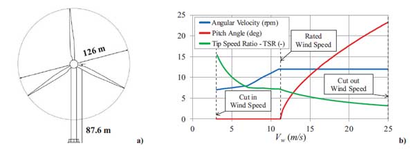
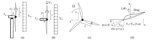
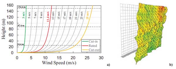
The wind turbine is an upwind, three-bladed, variable speed and variable pitch machine. The wind generator has a rotor diameter of 126 m with cut-in, rated, cut-out wind speeds Vw of 3 m/s, 11.4 m/s, and 25 m/s, respectively (Fig. 1a). The algorithm that controls the pitch and rotor speed is developed to optimise the power output for any wind speed. Cut-in speed divides the zone where the generator torque is zero and no power is extracted from the wind by the zone where the wind is used to accelerate the rotor for start-up. The rated wind speed is associated with the state when the pitch control is activated, and the blades start to be rotated, so that torque and generated power remain constant for higher wind speeds. Cut-out wind speed is the state when the rotor shuts down in high wind conditions, to avoid structural damage. For steady state conditions, the trends of rotor speed and blade pitch versus wind speeds ranged between the cut-in and the cut-out states are reported in Fig. (1b). In particular, the trends of the angular velocity of the rotor, Ω, and of the Tip Speed Ratio TSR (ratio between the blade tip velocity and the wind speed), are shown. The results presented in this paper, related to the operational conditions, are based on combinations of wind speed, rotor speed, and blade pitch, whereas the results given for the parked condition are based on a fixed rotor with feathered blades.
| Characteristic | Value |
|---|---|
| Rated Power | 5 MW |
| Type | Horizontal - Upwind |
| Control | Variable Speed, Collective Pitch |
| Rotor diameter | 126 m |
| Hub height | 87.60 m |
| Cut-in, Rated, cut-out wind speed | 3 m/s, 11.4 m/s, 25 m/s |
| Mass of Rotor | 110000 kg |
| Mass of Nacelle | 240000 kg |
| Mass of Tower | 347460 kg |
| Rotor Speed Range | 6.9 to 12.1 rpm |
| Tower top diameter, wall thickness | 3.87m, 0.019m |
| Tower base diameter, wall thickness | 6.00m, 0.027m |
| 1st Tower Fore-aft Frequency | 0.32 Hz |
| 1st Tower Side-to-Side Frequency | 0.31 Hz |
| 2nd Tower Fore-aft Frequency | 2.90 Hz |
| 2nd Tower Side-to-Side Frequency | 2.93 Hz |
The tower support structure is made of a steel tubular cantilever beam with a hollow tapered circular cross-section, having a total height equal to 87.6 m, with an external diameter of 6.0 m at the base and 3.87 m at the top. Shell thicknesses range from 27 mm at the base to 19 mm at the top. Further specifications of the HAWT can be found in [20].
2.2. Aeroelastic Model
2.2.1. Coupled and Uncoupled Approaches
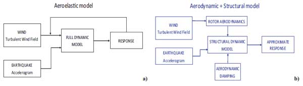
Wind turbines are highly dynamic and tightly coupled systems, characterizing a multi-physics problem: their structural design and assessment pose specific issues [21, 22]. The structural parts of a wind generator are subjected to aeroelastic effects due to the feedback of the blades motion on the aerodynamic forces. Therefore, the aerodynamic forces are dependent on the wind action and the dynamic response of the structure. The aerodynamic forces are affected by the turbulent wind field as well as the dynamic response of the HAWT tower structure when subjected to wind and seismic loads. An essential outline of an aeroelastic model, representing the dynamic response of the HAWT structure, is shown in Fig. (2a), and the general equations of motion can be expressed as follows:
 |
(1) |
where MHAWT, CHAWT and KHAWT are the structural mass, damping and stiffness matrices of the overall dynamic system, respectively; ẍ, ẋ and x are the time-dependent acceleration, velocity, and displacement vectors, respectively; Faerodyn (U, ẍ, ẋ, x) is the load vector due to the aerodynamic forces on the rotor blades, MHAWT Iẍg(t) is the seismic force vector, wherein I = [1,1,1,…..,1]T is the influence coefficient vector and ẍg(t) the input ground acceleration, and U is the turbulent wind field.
According to the equations of motion, full system modelling has to be developed with fully-coupled, nonlinear time-domain simulation capable of taking into account the coupled effects of the aerodynamic and seismic responses. Although fully-coupled approaches in time-domain are the most suitable choice to develop numerical analyses for seismic assessment, their main drawback is the high computational costs, which become rather prohibitive when several simulations have to be carried out.
As an alternative, in this study, the turbulent aerodynamic and the seismic loads, applied to the structural model of the HAWT, were calculated by decoupling the aerodynamic response of the rotor from the dynamic response of the tower structure. Based on this assumption, the aerodynamic forces are defined using a quasi-steady approach as [23]:
 |
(2) |
in which the aerodynamic forces are decoupled in a load vector of the aerodynamic forces acting on the rotor blades and in an aerodynamic damping matrix, Ca, in this case only related to the mean wind speed in the fore-aft direction, Vw.
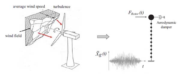
First, the response of the rotor with flexible blades, neglecting the elastic behaviour of the tower, is evaluated (i.e., rotor aerodynamics in Fig. (2b). Then, the dynamic loads deriving from the first step are imposed to the FEM model of the tower where the aerodynamic damping is embedded. The approximate structural response of the HAWT is evaluated by applying the wind thrust of the rotor and the seismic excitation to a dynamic model of the tower structure, neglecting any feedback. The HAWT tower structure is modelled using a FEM software (i.e., OpenSees). Two separate linear time-history analyses were developed, see Fig. (3): (i) the first applying the wind loads as a time-dependent rotor thrust to the tower top; (ii) the second applying the seismic excitation as a tower base acceleration boundary condition.
Within this decoupled approach, the effects of the aeroelastic interaction are taken into account including in the model an appropriate level of aerodynamic damping [24]. This decoupled pattern divided into an aerodynamic model of the rotor and a dynamic model of the tower structure with aerodynamic damping is also shown in Fig. (2b).
In the recent literature, the use of an uncoupled approach was applied and validated for NREL 5MW land-based HAWTs by Santangelo et al. [12]. Some comparative analyses in the time domain between the results obtained by the fully-coupled simulation performed in GH-BLADED [25] and those developed by a linear combination of separate wind and earthquake responses, the latter derived by adding different levels of aerodynamic damping, are carried out. The results show that the errors observed for the tower internal forces (bending moment and base shear) are within engineering margins. These results encourage the use of the uncoupled approach, confirming that an aerodynamic damping value of 4%, as recommended by ASCE-AWEA RP2011 [14] and in previous studies [3, 15], can reasonably be used in time-domain uncoupled analyses.
2.2.2. Aerodynamic Model
The aerodynamic response evaluation of the wind turbine was performed using the FAST code, developed by Jonkman and Buhl [18] at the National Renewable Energy Laboratory (NREL). FAST is specifically developed to simulate the turbine dynamic response and is capable of predicting both extreme and fatigue loads of two- and three-bladed horizontal axis wind turbine. The code uses a modal combination formulation with limited degrees of freedom to simulate the wind turbine behaviour in the time domain. The structural response is calculated by solving the equations of motion using multi-body dynamics formulation with elements whose flexibility is defined by summing specified mode shapes for different components.
FAST can be combined with the AeroDyn code developed by Laino and Hansen [26], that uses the Blade Element Momentum (BEM) theory proposed by Glauert [27], to calculate the aerodynamic forces acting on every element of each blade for every time-step. To this aim, the definition of drag and lift forces and angle of attack of the wind are taken into account to carry out the aerodynamic forces (normal, tangential forces, and pitch moments). The FAST program uses the Aerodyn code as a dynamic external link to apply the aerodynamic forces to the blade members of the modelled wind turbine. For given values of the mean wind speed and turbulence intensity, a wind velocity field is generated by Turbsim [28] and is used as input for the aerodynamic analyses carried out in FAST; the latter produces as output the time-history of the rotor thrust at the top of the tower, due to the wind in the operational and parked scenarios. The results of the FAST simulation are then applied to the tower FEM model as an external loading in addition to the seismic actions.
2.2.3. Structural Model
The dynamic structural model of the HAWT was developed in OpenSees [19] using Euler-Bernoulli cantilever beams (Elastic Beam-Column Element) discretized by 11 nodes into 10-beam elements, connected to a rigid foundation.
Thus, the effects of the pile and soil flexibility were not taken into account in this paper. The section properties of the tower elements are calculated from the stiffness properties given for the reference wind turbine. The steel material used for the tower has a Young modulus of 210 GPa, Poisson ratio of 0.3 and density of 8500 kg/m3. This density value is higher than the steels typical value of 7850 kg/m3 to implicitly account for paint, bolts, welds, and flanges that are not
considered in the tower thickness data [20]. The RNA mass is lumped at the top node, while the tower mass is concentrated at each corresponding node of the cantilever beam, representing the flexible model of the tower. The final structural model was tuned by adjusting the tower stiffness properties to match the first and second bending modes in all directions according to the structural model of the prototype 5 MW HAWT proposed by NREL [20]. A sketch of the tower structural model and the external loads, rotor thrust, and seismic input is shown in Fig. (3). Within the decoupled approach above mentioned, the equation of motion for the tower structure can be expressed as:
 |
(3) |
where MT, CT, and KT, are the tower mass (tower and RNA masses), damping and stiffness matrices, respectively; ẍ, ẋ and x are the time-dependent vectors of the kinematic parameters of the tower; FRotor (t) is the rotor thrust load vector, whose only non-nihl component is that applied at the top node, MT ·Iẍg(t) is the seismic force vector.
The total damping model is assumed as the sum of the structural damping and the aerodynamic damping, calculated for each parked/operational condition through the closed form approach suggested by Valamanesh and Myers [15]. For the structural damping, the mass and stiffness proportional coefficients of the Rayleigh model are calculated, while the aerodynamic damping is embedded in the model through a viscous damper placed at the top of the tower.
2.2.4. Aerodynamic Damping
The aerodynamic damping is an effect due to the velocity of a vibrating structure inducing a change in the aerodynamic forces, which generally reduces the dynamic response of the structure. This effect is related to the velocity term in the equation of motion producing feedback effects and is additive with structural damping [24]. It should be highlighted that additional damping generated by feedback effects occurs also in other cases than in the wind engineering such as pedestrian loads on footbridges [29, 30]. Moreover, it is well known that different values of the damping can strongly affect the seismic response. This strategy is widely used to reduce the structural response in seismic engineering by using specially designed devices [31, 32].
The same occurs in HAWTs where the response is made more complex by the variation of the magnitude of the total damping with the direction of vibration with respect to the rotor plane and the operational conditions, i.e., wind speed. In a decoupled approach, the aerodynamic damping is the key point to take into account the aeroelastic effects. Design guidelines for wind turbines lack specific recommendations on aerodynamic damping. For instance, IEC-61400-1 [13] includes provisions for calculating the required structural capacity under combined seismic and operational loads, with it suggesting to carry out the analyses with a structural damping ratio equal to 1%. In the code, no recommendations are explicitly made for taking into account the aerodynamic damping effect. A recently recommended practice, published by the American Wind Energy Association jointly to the American Society of Civil Engineers [14] suggests using a total damping ratio of 1% for non-operational conditions, and a total damping ratio of 5% for operational ones, to account for aerodynamic damping. The recommended practice makes no distinction between aerodynamic damping in the fore-aft or side-to-side directions.
In this paper, the estimation of the aerodynamic damping was developed using the closed form approach suggested by Valamanesh and Myers [15]. This solution, starting from the BEM theory, is based on some simplifying assumptions: (i) the flexibility of the rotor blades is neglected and (ii) a steady, uniform wind oriented perpendicular to the rotor plane is considered for its derivation. This approach allows to accurately consider aerodynamic damping within the software that has more refined structural analysis features. As above mentioned, the decoupling approach can be applied since wind actions and seismic excitation can be seen as independent phenomena.
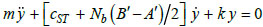
From the structural point of view, the derivation of the aerodynamic damping is based on a cantilever beam model of the HAWT tower with lateral stiffness k and with two degrees of freedom: the horizontal displacement at the hub height in the fore-aft (x-direction, perpendicular to the rotor plane) and side-to-side (y-direction, horizontal and in the rotor plane) directions. The mass of the RNA and of the equivalent modal mass of the tower are modelled as lumped mass m at the turbine hub. Estimating the aerodynamic forces, based on the BEM theory the equations of motions for the fore-aft (x) and side-to-side (y) directions can be written as:
 |
(4) |
 |
(5) |
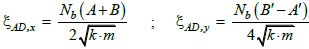
Consequently, the aerodynamic damping ratio ξAD,x in the fore-aft direction and ξAD,y in the side-to-side direction can be expressed as follows:
 |
(6) |
where Nb is the number of the blades in the rotor, cST is the structural damping coefficient; A and B are the portions of the aerodynamic force at the hub Fx in the fore-aft direction generated by the uniform upstream wind speed Vw and by the rotational speed
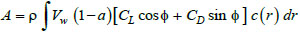 |
(7) |
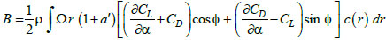 |
(8) |
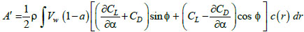 |
(9) |
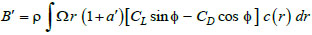 |
(10) |
where ρ is the air density, a and a’ are the axial and tangential induction factor, CL and CD are the lift and drag coefficients of the blade,
For the specific case of the NREL 5-MW HAWT, the aerodynamic damping ratio was calculated in the fore-aft and side-to-side directions, using the approach proposed by Valamanesh. A value of the air density of 1.25 kg/m3 was considered in the calculations. The results are represented in Fig. (5) as a function of the wind speed in the range of 0 – 25 m/s for both parked and operational conditions. The predictions of the aerodynamic damping, in the fore-aft direction, outcome in a maximum value of 0.1% for the parked condition, and in higher values ranged between 2.24% and 5.34%
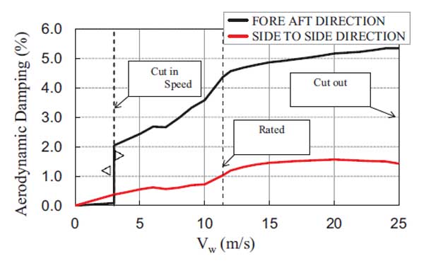
for operational conditions. The predictions for the side-to-side direction outcome in lower values of aerodynamic damping, ranging between 0.3% and 1.5% (mean value of 1%) for the operational condition. These values are quite consistent with those suggested by ASCE/AWEA RP2011 [14], which, however, provide the same value for all the direction of vibration.
3. RESULTS
In this section, the wind and seismic input actions adopted in the simulations will be introduced, and the results reported in terms of statistics of the response, with the fitted Generalized Extreme Value (GEV) probability distribution of the peak response being commented and described.
3.1. Wind and Seismic Actions
To properly simulate the wind loads on the blades, the simulation of random wind field velocity time histories is required. Wind velocity can be decomposed into a mean and turbulent part. Given that, wind velocity can be dealt with as a random process. The mean part is derived from probabilistic wind climate studies and the turbulent part is defined through Power Spectral Density and Coherence Functions.
The mean vertical wind profile, U(z), can be described using the logarithmic profile in atmospheric neutral conditions:
 |
(11) |
where zo is the roughness length, U(zr) is the mean velocity at the reference height, corresponding to the hub height zr. For given values of the mean wind speed and turbulence intensity, a wind field can be generated by TurbSim and will be used as an input for the aerodynamic analyses developed with FAST [18]. TurbSim is a stochastic, full-field, turbulent-wind simulator that uses a statistical model to numerically simulate time-histories of three-component wind-speed vectors [28]. TurbSim is able to support the spectrum proposed by Kaimal et al. [33] to simulate the wind fluctuations. This spectrum in the normalized form is given as:
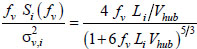 |
(12) |
where fv is the frequency in Hertz, Si the single-sided velocity component spectrum, σv,i the Standard Deviation of the i-th velocity component, and Li the velocity component integral scale parameter, and Vhub the wind speed at the hub height. The following exponential coherence model provided by the IEC Standard [13] can be used with the Kaimal spectrum [14] to account for the spatial correlation structure of the longitudinal velocity component:
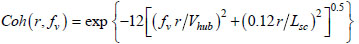 |
(13) |
where r is the magnitude of the projection of the separation vector between the two points onto a plane normal to the average wind direction, and Lsc is the coherence scale parameter.
The seismic action can be represented by a set of recorded, simulated or artificial inputs. Some specific rules can be found in EC8 [34]: the corresponding acceleration response spectra have to match, on average, the peak ground acceleration and the shape of the elastic response spectrum for 5% damping defined for the site. Moreover, EC8 provides further indications for the generation of artificial inputs, concerning the duration and the spectral shape.
3.2. Aerodynamic and Seismic Response of the Wind Turbine
The outcome of the combined effects of turbulent aerodynamic and seismic loads on the structural response of a HAWT was evaluated on the above mentioned decoupled dynamic model of the 5 MW, land-based turbine developed by NREL.
To define the wind action and consider various wind load combinations with seismic excitation, 12 different wind speeds were selected, ranging from 3 m/s to 25 m/s, evaluated at the hub height (equal to 87.60 m), to be tested on the model. For the parked and operational cut-in scenario, the same value of wind speed equal to 3 m/s was set. The rated wind speed of the turbine (11.4 m/s), associated to the state where the pitch control algorithm is activated, was also included in the range, as the final value of 25 m/s that corresponds to the operational cut-out scenario.
The roughness value for z0 equal to 0.05 m for all the wind scenarios and directions is assumed, that characterize areas with low vegetation and isolated obstacles.
For each value of the mean wind speed, 50 turbulent wind fields (grid 21 x 21 with a step of 6.50 m) were generated using Turbsim [28]. A Normal Turbulence Model (NTM) and medium turbulence characteristic of class B, as defined by the IEC-61400 standard [13], were assumed. The mean wind speed profile for all the wind speed conditions here accounted for, and a sample of the instantaneous turbulent wind field pattern is shown in Fig. (6).
Each wind field was applied to the Aerodyn module of the FAST program, so as to calculate the aerodynamic response of the rotor in time domain, for each mean wind speed level (parked and operational condition), obtaining 50 rotor thrust time-histories. In Fig. (7) the mean values (black points), the maximum values (red points) of the rotor thrust, and their average across the wind speed (black and red continuous lines) are shown. It can be observed that the rotor thrust is strongly related to the wind speed and pitch control mechanism in the blades that change the load pattern significantly (Fig. 1b).
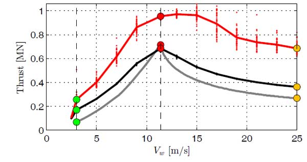
The rotor thrust increases up to wind speeds reaching the value of 11.4 m/s (rated condition), and decrease for increasing values of wind speed up to 25 m/s (cut-out). This trend is in good agreement with the corresponding one calculated through the BEM theory (grey continuous line). The observed differences are mainly due to the model assumed for the definition of the wind loads: turbulent wind field, in the first case, and steady-state wind condition in the second case. It is important to mention that turbulence effects, taken into account in the generation of the random wind fields, play a crucial role in the calculation of the maximum rotor thrust values that result relatively higher than those derived with the BEM theory, with an increase of 33.7% observed for the operational rated condition.
Each thrust time history was then applied to the top node of the tower structural model, so as to evaluate the corresponding structural response parameters in the fore-aft direction resulting from the linear dynamic time-history analysis.
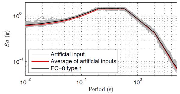
The structural model was then analyzed under the fifty artificial accelerograms. These input signals were generated using the SeismoSignal software [35], with a total duration of 25s, and a strong motion length of 15s. Their mean spectrum is never lower than 90% of the corresponding EC8 elastic spectrum Type 1 for class of soil C, with 5% damping ratio. The acceleration spectra of the artificial input and the corresponding EC8 target spectrum are compared in Fig. (8). These accelerograms were scaled to a peak ground acceleration ranging from 0 to 1 g.
Each ground motion was then applied as a boundary condition at the base of the tower in either the fore-aft or side-to-side direction and linear dynamic time-history analyses were carried out to evaluate the corresponding seismic response parameters.
For all the time-history analyses, the aerodynamic damping magnitude was set for each parked and operational condition at values here calculated for the fore-aft and side-to-side directions, using the closed-form solution proposed by Valamanesh [15] (Fig. 7). On the other hand, the structural damping was assumed to be equal to 1% of critical for all directions [13].
3.3. Probabilistic Assessment of the Peak Response
The structural response of the 5 MW HAWT tower subjected to the combined actions of wind and earthquake was evaluated using Monte Carlo simulations. For each working condition, the maximum value of the structural parameters was assessed for each combination of wind load (acting in fore-aft direction) and the seismic excitation applied in the fore-aft or side-to-side directions. The time-history response to wind load was calculated for a duration of 600s, and the ground motion was applied in the simulation after 400 s, allowing the transient behaviour of the turbine at the beginning of the simulation to diminish and not to affect the seismic response.
The outcome of the wind and seismic effects on the parked and operational wind turbine was analysed in terms of tower base bending moment and base shear, total drift ratio and rotation at the tower top. In fact, each wind response time history of the structural parameter was then combined with each seismic response time-history of the same parameter, so to obtain in the fore-aft and side-to-side directions a total of 2500 response time histories for each scenario (1 parked and 12 operational wind speed levels).
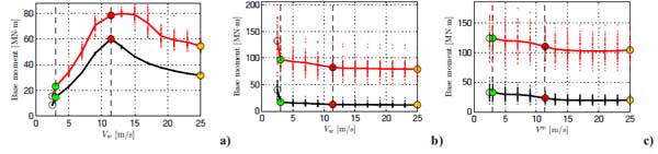
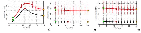
In Figs. (9-10) the trends of the tower base bending moment and base shear as a function of wind speed, are shown. The mean and maximum values of these structural parameters and their average trends are represented (i) for the case of the aerodynamic loads acting in the fore-aft direction (Figs. 9a-10a), (ii) for the case of seismic actions scaled to a peak ground acceleration of 0.5g acting in the fore-aft (Figs. 9b-10b) (iii) and side-to-side directions (Figs. 9c-10c). In the first case, the trend of the structural response parameters versus wind speed is very similar to that of the wind thrust showed in Fig. (7). Nevertheless, it should be noted that the maximum values of the structural response parameters occur for a wind speed of 13 m/s, slightly larger than the rated wind speed condition. Regarding the response to seismic actions in X-direction, the structural response parameters sharply decrease from the parked to the operational cut-in condition for a wind speed value of 3 m/s. Whereas, for the other operational conditions a slight decrease when the wind speed increases, due to the corresponding increasing trend of the aerodynamic damping, is observed. Similar trends are observed for the response to seismic action in the Y-direction, without considerable differences between the parked and cut-in condition.
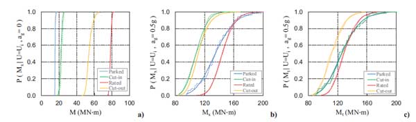
In Fig. (11a), the empirical Cumulative Distribution Function (CDF) of the tower base absolute maximum bending moment M, due to the wind action, is fitted to the Generalized Extreme Value (GEV) distribution. A similar probabilistic estimation in terms of GEV distribution was carried for the case of the peak acceleration induced by walkers on a pedestrian bridge [36]. As expected, the values of the bending moment increase with the operational wind speed up to the rated value and then decrease with further increasing of the wind speed up to the cut-out condition. Moreover, for the wind speed level of 3 m/s, the difference between the tower base absolute maximum bending moment noted in the parked, and operational conditions are due to the lower rotor thrust values obtained for the parked condition with respect to that calculated for the operational condition. The empirical and fitted CDF of the tower base maximum bending moment are also shown for the combination of the turbulent aerodynamic and seismic action, scaled to a peak ground acceleration of 0.5 g, acting in the fore-aft (Fig. 11b) or side-to-side directions (Fig. 11c). Generally, an increase in turbine tower base moments is observed. In particular, when the seismic action is in the fore-aft direction, the operational rated scenario brings the most significant values of the tower base absolute bending moment (mean value of the location parameters μ of 144.2 MN·m). Moreover, for a wind speed of 3 m/s, the combined effect of the wind loads and seismic excitation is greater for the parked condition (mean value of μ equal to 134.8 MN·m) if compared with the operational condition (mean value of μ equal to 108.5 MN·m), due to the lower aerodynamic damping. Vice versa, when the seismic load is in the side-to-side direction, the bending moment largest values occur for the parked condition (mean value of the location μ of 125.1 MN·m).
The variations of the GEV Probability Density Function parameters (shape κ, scale σ, and location μ), of the maximum base bending moment and base shear, maximum total drift ratio (top displacement divided by the tower height) and top rotation, depending on the wind speed for increasing values of peak ground acceleration ag, are shown in Figs. (12-13-14-15). The first two force parameters, mainly related to the Ultimate Limit State are used to develop the strength checks, while the last two kinematic parameters concern the Serviceability Limit State and are used to prevent the shut-down conditions.
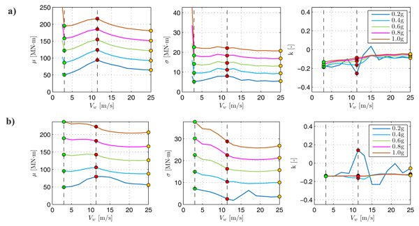
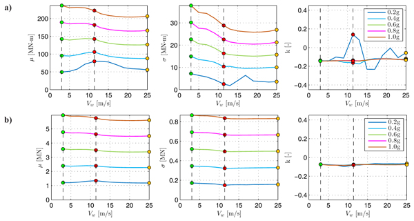
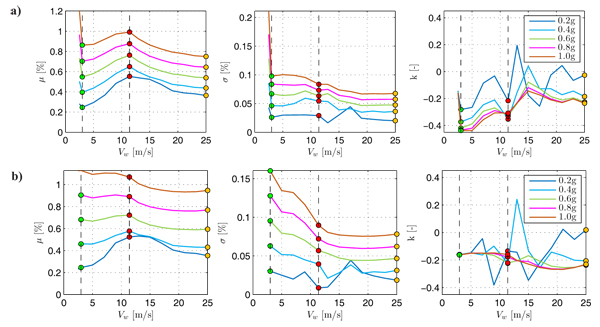
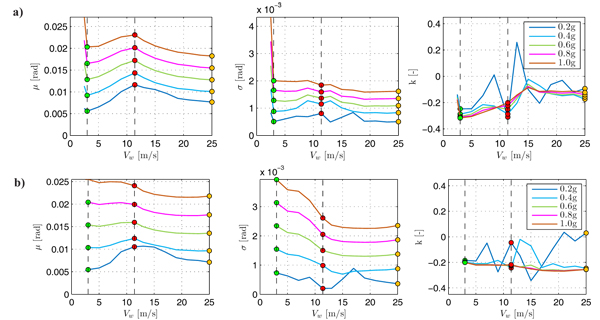
By observing Figs. (12-13-14-15), it can be seen the general increase of the location and scale parameters with ag for all wind speeds. Usually, the maximum demand in terms of all the structural response parameters is associated with the operational rated scenario. However, it is noted that for the high value of peak ground acceleration (ag > 0.6g) only the parked condition gives larger results if compared to the others, due to the absence of aerodynamic damping. Therefore, the parked scenario reveals to be critical for high values of peak ground acceleration.
Similar trends are observed for the combination of wind and seismic loads acting in the fore-aft direction and side-to-side direction, respectively. In these other cases, all the scenarios associated with wind speed values less than 11.4 m/s are more demanding if compared to the operational rated one for high values of peak ground acceleration. However, in these last cases, it is noted that the parked scenario becomes critical starting from a lower value of the peak ground acceleration (ag > 0.5g).
Finally, it is observed that the trends of the shape parameters tend to stabilize at a constant negative value for peak ground accelerations larger than 0.4g. In these cases, the probability distribution of the structural response parameters can be represented using a reverse Weibull or Type III Extreme Value Distribution.
CONCLUSION
In this study, the probabilistic assessment of the peak response of a land-based horizontal axis wind turbine HAWT subjected to the combined effects of wind and seismic actions is calculated through Monte Carlo simulations. The analyses were carried out using two open-source software (i.e., FAST and OpenSees) to minimize costs. For the first time, the GEV parameters of the maximum base bending moment and base shear, maximum total drift ratio and top rotation, depending on the wind speed for increasing values of peak ground acceleration, are calculated.
First, the turbulent aerodynamic and seismic effects on the structural model of the HAWT were assessed decoupling the aerodynamic behaviour of the rotor from the dynamic response of the tower support structure. This was achieved by evaluating the aerodynamic response of the rotor subjected to wind loads through aerodynamic analyses developed in FAST computer program.
Then, the structural response of the HAWT was calculated applying the wind thrust of the rotor and the seismic excitation to the tower FEM model, developed in OpenSees, therefore neglecting aeroelastic feedback. Thus, the aeroelastic effects were considered through the addition of aerodynamic damping to the structural model, evaluated by using the closed form approach proposed by Valamanesh and Myers [15].
Finally, the role played by the seismic loads if combined with the operational wind loads is presented and discussed. To this aim, the probabilistic assessment of the peak response of the tower structure was evaluated calculating the maximum values of the structural response parameters. In particular, the empirical and the estimated CDF of the tower base bending moment were evaluated for the combination of wind and seismic actions. Moreover, the results in terms of variation of the GEV parameters, of the maximum value of the response parameters (base moment and shear, total drift and top rotation), expressed as a function of wind speed for increasing values of peak ground acceleration, show that the maximum demand is associated with the operational rated scenario. However, it is noted that for a high value of peak ground acceleration, the only parked condition gives greater results if compared to the others, becoming dominant for high values of peak ground acceleration, higher than 0.6g for earthquake in the fore-aft direction and 0.5g for earthquake acting in the side-to-side one.
The approach presented herein lends itself to the complete multi-risk analysis of the land-based structures if the structural capacity and the hazard characterization are added to the model.
CONSENT FOR PUBLICATION
Not applicable.
CONFLICT OF INTEREST
The authors declare no conflict of interest, financial or otherwise.
ACKNOWLEDGEMENTS
Declared none.

