All published articles of this journal are available on ScienceDirect.

Corrosion in Concrete Structures with Permanent Deformation in Marine Environment
Abstract
Concrete is usually highly alkaline (pH around 12), thus protecting reinforcement against corrosion. The occurrence of oxides is favored when the medium pH surrounding the bar is in values near to 9 or lower. Aggressive substances for reinforcements generally enter concrete through its pore structure, and cracks tend to decrease pH, stimulating corrosion process. There are several causes for cracks, including structure bending caused by loads. This research established the influence of concrete coating cracks, caused by permanent deflection, on the durability of reinforced concrete beams in contact with chloride-containing water (at a similar ratio as seawater), over a five-year period. It analyzes the influence of deflections suffered by the specimens on corrosion potentials and concrete coating cracking. It was established that, from the durability point of view and for structures exposed to marine environment, it would be advisable to set stricter admissible deflection and/or concrete cracking limits than those set by the analyzed standards.
1. INTRODUCTION
Every concrete structure has a given service life, directly related to:
- the environment it is exposed to (presence of aggressive elements, temperature, humidity, etc.);
- its design, i.e., the concrete outer shape, reinforcement coating, etc.;
- the quality of materials used; and
- the mechanical stress it is subject to.
It is very well known that concrete’s resistance to tensile stress is low, a fact that leads to the introduction of steel bars inside its mass, so that these bars absorb the tensile stresses. In this way, both reinforced and pre-stressed concrete overcome the usage limitations of plain concrete, but several factors can affect the durability of a concrete structure: carbonation, sulfates, chloride ion and stray current [1].
In standard conditions (in non-aggressive environments, under careful elaboration, working and execution), concrete provides enough protection to the steel bars against corrosion due to its alkalinity, for a certain period of time. But if any of those conditions is not met, corrosion problems could begin in the reinforcement bars, which could lead to the element’s or structure’s collapse. However, if the deterioration is found on time, repairs can be made by reinforcing them with composite materials [2].
When corrosion of reinforced concrete structures takes place, the transformation of metallic iron into oxide is accompanied by a volume increase that can reach up to 600% of the volume of the original iron, depending on the oxidation state. This increase in volume of the oxides is the main cause of the expansion and cracking of the concrete. That occurs because these products initially stay on the surface of the bar, trying to occupy the empty spaces of the adjacent concrete pore structure. Later, they press on the cover concrete, because their volume is greater than that of the basic metal, and cracks are generated when its tensile stress limit is exceeded. These cracks begin to appear on the surface of the bar but soon reach the surface of the concrete cover and develop longitudinally throughout the bars. The main structural damages are the reduction of bars useful diameter, the loss of bond between the steel bars and the concrete, the steel embrittlement and the cracking of the concrete [3].
Due to the importance of structures built in marine environments, different studies have been conducted, some of them over several years [4, 5]. There are several previous studies about reinforced concrete elements subject to the accelerated corrosion of their reinforcements exposed to their dead load only [3, 6-9]. Other studies analyze structures subject to live loads [10, 11].
Generally, beams are subject to flexural stress that causes deformations and results in cracking crosswise to the beam major axis. These cracks are very important because they can act as access points for external aggressive substances, in this case, water with chlorides. Chlorides diminish the steel-concrete interface pH leading to the damage of the outer layer of stabilized oxides which protect the steel, producing reinforcement depassivation. Moreover, these cracks enable a more direct contact of the reinforcement with the air oxygen, one of the essential elements in corrosion processes. As the corrosion process develops, the resulting rust occupies a greater volume than the original corroded steel. This leads to other cracks, additional to bending-caused cracks, creating a feedback loop for the process.
All investigations related to pathologies generated in reinforced concrete, as is the case of the corrosion of reinforcements in structures subjected to mechanical stresses, are of great importance, as they affect the durability of the structures and consequently their shelf life [12], being reinforced concrete the most commonly used material for structural purposes in the construction industry.
This study analyzes reinforced concrete beams, with permanent deflections, exposed to water with dissolved chlorides, at concentrations similar to those found in the Atlantic Ocean. The specimens are subject to a naturally occurring corrosion process which has not been accelerated through external currents, as is usually done for this kind of research. This was a five-year research, and the cracking and corrosion potentials were monitored over this period.
2. EXPERIMENTAL METHODOLOGY
2.1. Samples Constructions
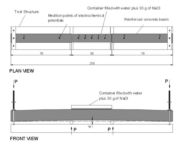
To conduct the research, five 0.08 m wide reinforced concrete beams with different heights were built, so that, once the deflections were introduced, the reinforcements subject to corrosion have the same initial stress (210 MPa). This constant stress was adopted considering the influence it has on the speed of this “corrosion under stress” process. The beams, once built, were wet cured. Table 1 shows the geometric characteristics, reinforcements, end-applied loads and deflection imposed on the center of the beams. A 2.5 coating / bar diameter (c/ϕ) ratio, constant across all beams, was used. The beams had 0.0042 m stirrups each 0.10 m.
The concrete was poured into the moulds, then vibrated mechanically in three layers (with a lab vibrator, diameter of 0.025 m, frequency 10500 rpm.) and cured (by moistening) during the first 7 days. From this time, the beams were kept in laboratory environment (temperature around 20 ºC, relative humidity around 50%). Besides, cylinders concrete samples (0.15 x 0.30 m) were made to characterize their mechanical properties [13, 14]. After 28 days of wet curing, they were tested and the following average strengths were obtained: Compression: 47.6 MPa and Indirect Tension: 5.6 MPa.
Fig. (1) is a schematic representation of the trial, which shows a bottomless container filled with water plus 30g of NaCl/l (513 mols/m3) and placed in the center at 0.50 m (the solution is in direct contact with the upper face of the beam). This area, limited by the reactions (of P value), is under a constant stress condition. The goal is to simulate an area of a structure in contact with seawater, not completely immersed and accessible to oxygen. This could be the case with a structure located in a tidal area. If placed in this kind of environment, concrete encounters high humidity, chlorides and oxygen that enter through the immersed area sides. Considering the stress condition of the reinforcements, all the necessary conditions for corrosion under stress are present. The concentration of chloride-containing water was maintained, placing a polyethylene protector on the top of each container and changing the solution every month.
In this research, a 0.02 m coating was used, less than the standard-recommended coating [10, 13] for marine environment, in order to obtain visible results within reasonable test time.
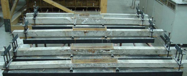
Five test points were established in the central area, which is permanently damp, while four others were established outside this area (two on each side). It is possible to consider that in Points 1 and 9, which are permanently damp, there is stress-free corrosion, as the reinforcement stresses are minimum due to their proximity to the supports, while in Points 2 and 8, close to the humidified area, as the process advances, it spreads around. It is worth mentioning that the tested face is the lower one, considering the concrete direction inside the shuttering. This is the least porous concrete, produced by mild material segregation during concrete casting [6] and it was considered the best representation for the simulated situation. Fig. (2) shows a photograph of the laboratory trial on the five beams [15].
| Beam N° |
Hight (m) |
Reinforcement | Cover (m) |
Load P (N) |
Deflection d (m) |
|---|---|---|---|---|---|
| 1 | 0.050 | 2 Ø 0.008 m | 2 | 800 | L / 200 = 0.0100 |
| 2 | 0.070 | 2 Ø 0.008 m | 2 | 1350 | L / 300 = 0.0067 |
| 3 | 0.082 | 2 Ø 0.008 m | 2 | 1710 | L / 400 = 0.0050 |
| 4 | 0.094 | 2 Ø 0.008 m | 2 | 2020 | L / 500 = 0.0040 |
| 5 | 0.104 | 2 Ø 0.008 m | 2 | 2300 | L / 600 = 0.0033 |
2.2. Materials Employed
Characteristics of concrete employed on the beams are shown in Table 2. An effort was made to maintain, in the prismatic samples, the same materials and identical ways of curing and constructing as in the beams.
| Component materials (kg/m3 of concrete) | |
|---|---|
| Common Portland cement | 480 |
| Fine aggregate (natural siliceous sand) | 815 |
| Coarse aggregate (crushed stone) | 876 |
| Drinkable tap water | 190 |
| Plasticezer (lts) | 1.7 |
| Set-retarding admixture (lts) | 4.8 |
| Water/cement ratio | 0.40 |
| Average fluidity (Abrams cone) (m) | 0.08 |
| Average compressive strength (MPa) (28 days) | 47.6 |
| Average tensile strength (MPa) (28 days) | 5.6 |
3. RESULTS
3.1. Corrosion Potentials
From the beginning of the trial, the corrosion potentials, in the points indicated in Fig. (1), were monitored according to ASTM C 876-91 [16] and IRAM 1546 [17] standards. The measurements were obtained using a PROCEQ voltmeter, and a Cu/CuSO4 electrode as reference.
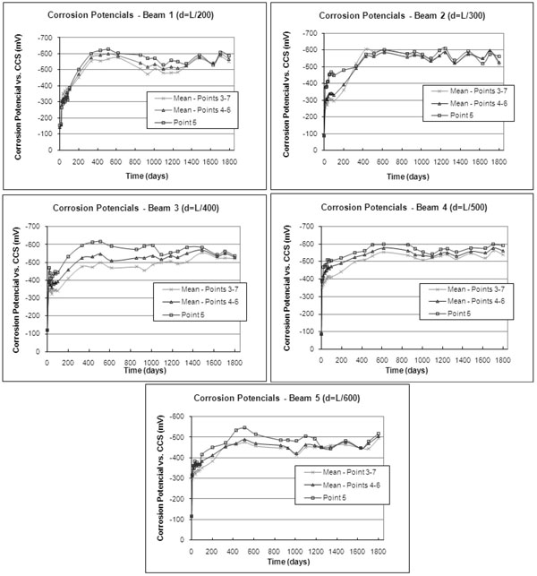
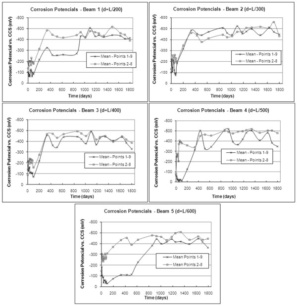
Fig. (3) shows the changes in Corrosion Potentials over time for the immersed beam points. As they hold a symmetric position, the average between items 4 and 6, as well as 3 and 7 is estimated. Besides, the potentials increase sharply during the first 400 days and then they remain almost constant over the following four years. Many of the points show a mild tendency towards passivity, similar to that occurring in processes where corrosion is accelerated by means of an external current [9, 10, 14]. The five points show similar behavior and those closer to the middle of the beams reached slightly higher values than the rest.
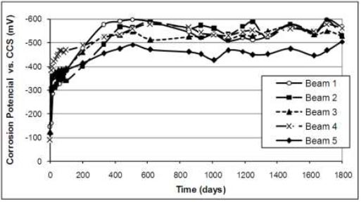
Fig. (4) shows the evolution of potentials, estimated as the average of the immersed points. In Beams 1 to 4, the potentials remain within similar values, ranging from -500 to -600 millivolts, while in Beam 5 (less deflection) potentials are below -500 millivolts, i.e., the process is less active.
Fig. (5) shows the corrosion potential averages for non-immersed points, located at beam ends (Points 1 and 9) and for those close to the immersed area (Points 2 and 8). In the first of these areas, and during the period that ends between 400 and 900 days, a sharp increase is observed followed by variations, but without a clear tendency towards activation or passivity. All beams have similar values, ranging from - 400 to -500 millivolts during the last three years. Values are more random than for immersed points. On the other hand, for all beams, in Points 2 and 8 a potential between -450 and -500 millivolts is reached approximately a year after the trial start, followed by variations, but without a clear tendency towards activation or passivity.
It is worth mentioning that the first signs of corrosion in reinforcements are stains on the concrete surface. These are followed by cracks that evolve over time. Nevertheless, it is observed that the areas with outer rust stains normally correspond to points where the corrosion process is more active (higher corrosion potentials).
3.2. Cracking Research
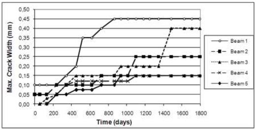
From the beginning of the test, the beam surface was observed on a daily basis and the onset date of the first stains and cracks was recorded. From the onset of the first cracks, regular measurements of their length and width were obtained with a graded ruler of a 5x10⁻⁵ m accuracy.
It is known that cracks known as “flexural cracks” are generated when stresses in the tensed areas of flexural reinforced concrete structures exceed the concrete’s tensile strength. They are identifiable by their transverse direction with regards to the main reinforcement bars. If the bars are also in a corrosive process, the corrosion products generate internal pressures because their volume is larger than the material from which they were originated. These pressures cause some products to fill the pores, others move to the exterior through the flexural cracks (if any) and the rest generate stresses. When these stresses exceed the concrete’s tensile strength, they cause lengthwise cracks to appear. These cracks will be known as “corrosion cracks”.
The aforementioned difference in crack direction allowed us to classify them in that way. But it is important to note that both types of cracks are linked by a close relationship. In fact, the presence of flexural cracks accelerates oxygen, water and chlorides’ penetration towards the rebars, favoring their corrosion process. On the other hand, since flexural cracks are exit ways for a part of the corrosion products, they could expand. Total growth of cracking causes the decrease of the load-bearing section of the beam (due to loss of the areas of steel and concrete) which could result in the structure’s collapse under heavy loads.
The survey of the Total Cracking Areas (Flexural Cracking Areas + Corrosion Cracking Areas) has been shown in Fig. (6), as a function of test Time.
Initially, there are flexural cracks that increased in size. Corrosion cracks were visible after a year, and they increased constantly (Figs. 6 and 7). During the last year, important concrete deterioration was observed, especially in beams with higher deflections (L/200 y L/300), which included spalling of thin concrete layers in the mid-third section of these beams, and the sealing of many cracks due to the NaCl buildup.
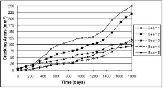
As the trial progressed, coating concrete delamination (during the last year) was observed, and NaCl buildups on the concrete surface that filled cracks forced the discontinuation the trial after 1800 days (approximately 5 years).
Table 3 shows trends of cracking areas and maximum cracking width in time, expressed in linear equations, obtained by minimum square method. The analyzed periods were 1800 days.
| Beam | Cracking areas | Maximum cracking width | ||
|---|---|---|---|---|
| Lew | R2 | Lew | R2 | |
| Beam 1 | y = 0,1282 x + 1,5998 | 0.97 | y = 0,0002 x + 0,1401 | 0.76 |
| Beam 2 | y = 0,1084 x – 8,342 | 0.94 | y = 0,0001 x + 0,0475 | 0.89 |
| Beam 3 | y = 0,0637 x – 0,9815 | 0.99 | y = 0,0002 x – 0,0018 | 0.87 |
| Beam 4 | y = 0,0572 x – 10,697 | 0.91 | y = 0,00006 x – 0,0625 | 0.63 |
| Beam 5 | y = 0,0574 x – 9,9234 | 0.97 | y = 0,00008 x – 0,0327 | 0.79 |
4. STANDARD RECOMMENDATIONS
This item will discuss CIRSOC 201 Standard [18], based on ACI 318-08 Standard, the CEB-FIB 1990 Model Code [19] and Spain´s Instruction of Structural Concrete [20]. These namely standards limit deflections of structural elements subject to flexural stress. For the cases analyzed here, ie beams, the standards set minimum heights and maximum admissible deflections. In this research, as the height of beam was established so that longitudinal reinforcements were subject to the same stress, the dimensions are not those generally used, thus the comparison should be based on deflections. An indirect method for measuring them may be based on the cracking in concrete tensile area, which is why standards [19, 20] limit the maximum width of cracks, before corrosion, that in this case, were produced by bending, but this type of cracks, in other cases, could be the consequence of rheological phenomena or other factors [21].
CIRSOC 201 [18] establishes maximum admissible deflections based on compatibility with non-structural elements, which might be damaged by deformations. The most stringent limit is L/480. Besides, it sets minimum heights for elements subject to bending, but does not set more stringent restrictions for structures in aggressive environments. In the comments section of this standard, Section C 10.6 reads: “Exposure tests indicate that concrete quality, proper compactness and proper concrete coating could play a more important role in corrosion protection than the width of cracks on the concrete surface”. Thus, no limits are set for crack widths.
The CEB-FIB Model Code (item 7.5) [19] indicates the analysis of a Limit Deformation Condition, not by setting maximum deflections, but by setting minimum heights for beams. Nevertheless, it recommends, for “simple verifications” the adoption of a limit deflection of L/300. Item 8.4.5 states that “the corrosion risk and speed in cracked areas depend mainly on the impermeability and thickness of the concrete coating,” and then it goes on to say that “even though experiments and practical experience show that the crack width affects the onset period, it is impossible to limit the crack width enough to avoid depassivity during the service life in regular reinforced concrete elements. Once the reinforcements are depassivated, the crack width does not influence the corrosion speed. Therefore, it is not considered necessary to set different limit widths according to the environment for regular reinforced concrete pieces.” Thus, the crack width is limited to 3x10⁻⁴ m, for any given environment. Nevertheless, the code states that, under extreme conditions, lower values might be set. A more recent standard, like the Spanish one, establishes, under item 49.2.4, that for reinforced concrete structures in marine environment (tidal area), the maximum crack width value is 1x10⁻⁴ m. For prestressed structures, these two standards set much more stringent cracking conditions.
5. RESULT ANALYSIS
Fig. (4) shows that after 90 days, all the beams have less than -350 millivolts. When this value is exceeded, it is possible to say that there is a 90% chance that corrosion is affecting the reinforcements [10, 13]. This indicates that an active corrosion process starts after approximately three months, despite the good quality of the concrete (H-40). Therefore, permanent deflections leading to cracking should be kept to a minimum to extend the service life of the structure.
It is possible to say that the corrosion potentials at beam end points are around 20% lower than in the middle of the beam. This reduced activity process at the beam ends is due to the fact that, as there are no cracks, there is less chloride-containing water penetration and oxygen penetration is also more difficult.
The electrochemical behavior of beam ends (Fig. 5), from the trial first year of the test, is similar to that of Beam 5 at the immersed middle points (Fig. 4). Therefore, and considering the reduced cracking areas, it is possible to infer that with maximum deflections of L/600, or less, the concrete structure situation would be similar to that beams without deformation (and therefore, without flexural cracking.)
Figs. (6) & (7) and Table 3. show the beams with greater deflections are the ones with greater cracking. Examination of cracking maximum widths in Beams 4 and 5, shows that at the end of the process they have the lowest values. Therefore, it is possible to say that initial flexural cracking affects the development of the corrosion process and that Beam 5 suffered less severe damages than the other beams. Even though initial cracking was below the limits set by the European standards [19, 20] in all cases, the difference lies in the initial flexural cracking area, so just limiting the maximum cracking widths seems to be an inadequate approach.
In relation to the maximum deflections indicated by the standards [18, 20], Beam 4 (L/500 deflection) and Beam 5 (L/600 deflection) are within admissible limits. Beam 4 had a final cracking area a bit over the values observed for Beam 5, but its Corrosion Potentials are higher (approximately by 100 millivolts) and this could result in greater damage in the long run. Based on the information mentioned above, using a durability criterion instead of the usual compatibility one, it would be possible to think of a maximum admissible deflection of L/600 for structures located in a marine environment. It would be advisable to analyze the possibility of conducting further research using beams with greater concrete coating, in order to establish a more accurate deflection limit.
However, according to the test it took the chlorides 3 months to penetrate the 0.02 m coating and reach the reinforcement, producing its depassivity. Instead of a 0.02 m coating, a 0.05 m one could have been used, which would have been appropriate for a marine environment. A widely used equation states that the chlorine penetration depth is proportional to the product of its access speed, multiplied by the time square root [22]. With the 0.05 m coating, applying this equation and considering chloride penetration speed a constant, the time to depassivity would have been 19 months. If we consider that increased coating thickness leads to less oxygen availability and greater concrete section to withstand tension caused by corrosion products, a study under these conditions would have taken at least 10 years. But, based on the reasons stated in 3.2, which prevented the study from lasting more than 5 years, the only possibility would have been to continue performing electrochemical measurements.
Bearing in mind that structural engineers are used to working with the deformation or displacement of the structures they design rather than predicting the width of the cracks on the structure, we consider it advisable to establish standard limits for any of these two parameters.
CONCLUSION
Based on experimental data obtained over the 5 year period of this research, it is possible to conclude that:
- Permanent deflections of structural elements exposed to severe environmental conditions should be reduced to a minimum, since corrosion processes can start to develop only a few months after the structure is in use.
- Evidently, for structures exposed to a very aggressive environment, setting maximum cracking widths is not enough. It would be advisable to establish maximum cracking areas per structure surface unit. For structures subject to bending stress, it is easier to predict their displacement; therefore, it would be necessary to set a maximum deflection value, from the durability point of view.
- All beams are stabilized in their corrosive processes. Nevertheless, Beam 5, with a maximum deflection of L / 600, showed less corrosive activity and less cracking than the other beams. Therefore, considering the durability, this deflection value may be an advisable limit for reinforced concrete structures in the marine environment.
CONFLICT OF INTEREST
The authors confirm that this article content has no conflict of interest.
ACKNOWLEDGEMENTS
The authors wish to express their gratitude to Materials Laboratory, Engineering Department and to technician J.P. Gorordo and the Science and Technology Secretariat, all of them from the Universidad Nacional del Sur, for their collaboration in the completion of the tests. We also wish to acknowledge the assistance of D. Bengoechea, G.D. Ercolani and L.V. González de la Paz, who as scholarship student have assisted at different periods of this work.

