All published articles of this journal are available on ScienceDirect.

Experimental Investigation of Ultimate Shear Force Capacity of Glulam Reinforced with Glued-in Threaded Rods
Authors Info & Affiliations
Abstract
Background:
Glued-in threaded (GIT) rods have been considered an effective timber connection method having several advantages, such as high load-carrying capacity, great stiffness, and good fire resistance. This type of connection has widely been utilized in newly built modern timber structures and for reinforcing the existing ones.
Objective:
The purpose of this experimental research is to investigate how the ultimate shear force capacity (USFC) of glulam is affected if it is reinforced with GIT rods and to study the interaction between the glulam and GIT rods. The results of this research can help researchers and engineers to select a suitable method of reinforcing the glulam with GIT rods at a superior inclination angle (IA) to the fiber direction in order to achieve higher USFCs.
Methods and Experimental Tests:
A total of forty glulam samples were tested for failure. The experimental tests consisted of five different series of samples with eight samples in each series. Sample series 1 were unreinforced glulam. Sample series 2 and 4 were glulam reinforced with the GIT rods at two different IAs of 45° and 90° to the fiber direction, respectively. Sample series 3 and 5 were glulam reinforced in the same way as sample series 2 and 4, but they were split in the middle. The samples were tested for failure using a standard testing machine. The machine was connected to a computer that recorded all the values obtained from the tests.
Results:
The results of the study were obtained as force-displacement graphs. The stiffness of the samples and interaction between the glulam and GIT rods were also calculated. The results achieved from the experimental tests of different series were compared and discussed.
Conclusion:
The experimental tests resulted in a 12.5% increase in the average USFC of sample series 2. However, the average USFC of sample series 4 was not enhanced significantly. The interaction between the glulam and GIT rods was obtained as 31.8% for the samples with reinforcing at the IA of 45° to the fiber direction and 3.8% for the samples with reinforcing at the IA of 90° to the fiber direction. Reinforcing the glulam with the GIT rods demonstrated the potential of enhancing its USFC. However, reinforcing the glulam with the GIT rods at the IA of 45° to the fiber direction was found to be superior to reinforcing the glulam with the GIT rods at the IA of 90° to the fiber direction.
1. INTRODUCTION
Timber has been used as a building material for many years and is still currently utilized extensively. Timber is an anisotropic material, which affects its strength. The strength of timber is dependent on its fiber direction, and it has higher strength parallel to the fiber direction compared with perpendicular to the fiber direction.
Since timber is considered to be a sustainable, lightweight, and aesthetic building material, its use for building projects is becoming more popular. Several hybrid timber-based structures have been built over the last decade. The world’s tallest timber building, “Mjøstårnet” in Brumunddal, Norway, was completed in 2019 with 18 stories and 85.4 m in height [1]. The building “Saras Kulturhus” was completed in Sweden in 2021 with 20 stories and 80 m in height [2]. Another tall timber building is “Brock Commons Tallwood House”, which is an 18-storey student residence completed in Vancouver, Canada in 2017. The structure has 18 stories with 54 m height [3]. Timber structures have proven to be appropriate and practical in a variety of boundary conditions [4], giving architects and engineers a flexible design process [5]. Light wood-frame construction is a common construction method for timber buildings. This system permits some structural components to be prefabricated, which cuts down on construction time and on-site fabrication errors [6]. Due to the affordability and capacity of wood framing to store carbon, it is being promoted as a structural system for buildings [7]. The refined engineered timber product, glued-laminated timber (glulam), is widely utilized in projects to cope with the limitations of traditional timber elements [8-13]. Many brand-new, unproven cladding systems and materials are being introduced at the same time. However, owing to the natural variation of material properties and anisotropic features of timber, designing timber elements is associated with more challenging issues than other types of elements [13, 14].
Glulam is primarily used for load-bearing structures with large spans, as the strength of glulam is higher than that of ordinary timber. Glulam was developed in the 1920s to improve the properties of timber, such as defects and cracks. This has resulted in a more homogeneous material. Glulam is usually composed of spruce and is made up of slats that are glued together to the desired dimensions. Glulam is used for beams, columns, arches, and frames.
When beams are designed for long spans, saddle beams can be employed. The saddle beams have the smallest cross-section at their supports, where shear forces are the greatest. This means that the shear forces become decisive in design and not the bending moment at the center of the beams. By reinforcing the beams at the ends, a smaller cross-section could be utilized at the beams’ supports, thus minimizing the use of material.
Two separate timber members can be connected to each other by glued-in steel rods, making a permanent connection [15, 16]. Such a hybrid connection is mostly assembled on-site, which has been demonstrated to take a high risk of being improperly bonded by steel rods and glue [16, 17]. Thus, it is recommended to do the gluing process in a controlled environment, where a proper bond of the adhesive can be checked and ensured. Moreover, using the embedded rods has the advantage of the fire resistance aspect compared with other types of connections because, in this type of connection, the steel rods are concealed inside the timber section. Moreover, to erect timber structures, special attention should be paid to the connections owing to the complexity of the material properties and the mechanism of the internal force transfer between the elements. The stiffness of the timber structures depends on the resistance and stiffness of the connection [18]. Consequently, the connections in the timber structures greatly influence their structural performance [14].
Traditional carpentry joints, dowels, and nails have been utilized to connect timber structures. There are many connecting systems available today that use various methodologies and are appropriate for use in a variety of contexts. Using glued-in rods is one of the recent methods of connecting timber elements. By drilling holes in timber, a rod that is fastened with glue can be inserted to connect the pieces, forming an internal coupling [19].
For many years, adhesive joints have been applied in timber buildings. Modern timber structures are effectively built using hybrid joints with glued-in rods for both new constructions and reinforcing [20]. Serrano [21] provided a test method to obtain the strength and fracture characteristics of the bond of glued-in rods for timber structures. Pull-out strength tests on glulam made of Norway spruce with glued-in steel rods were reported by Widmann et al. [22]. Denzler and Glos [23] presented the results of shear tests carried out according to the European Standard EN 408 [24]. Practical and theoretical approaches from research done on joints with glued-in steel rods were summarized by Tlustochowicz et al. [20]. Dietsch and Brandner [25] conducted a study to find out where and how reinforcing glulam beams with self-drilling screws and threaded rods should be done. Ahlskog and Ross [26] studied how saddle beams can be reinforced for shear forces. The influence of the bond-slip location effect on the bond behavior between glulam and glued-in rod was numerically investigated by Ling et al. [27]. Experiments on glulam connections with glued-in single steel rods were performed by Ling et al. [28]. Xu et al. [29] did an experimental investigation on joints composed of multiple glued-in steel rods in glulam with the pull-out failure mode. Hubbard and Salem [16] conducted experimental research on a tension connection configuration that made use of threaded steel rods which were mechanically fastened into glulam sections. Navaratnam et al. [13] reported the outcome of a study on the experimental assessment of the mechanical performance of a glued-in rod to glulam beam to column moment connection. However, there has been limited research on the ultimate shear force capacity (USFC) of glulam using glued-in threaded (GIT) rods, which is the focus of this article.
The current article evaluates how the USFC of glulam is affected if it is reinforced with the GIT rods. Also, the interaction between the glulam and GIT rods is examined. Forty samples are experimentally tested for failure. The experimental program includes five different series with eight samples in each series. Sample series 1 are unreinforced. Sample series 2 and 4 are reinforced with the GIT rods at two different inclination angles (IAs) of 45° and 90° to the fiber direction. Sample series 3 and 5 are reinforced in the same way as sample series 2 and 4, respectively, but they are split in the middle. The results are obtained from the tests and compared.
2. METHODS AND EXPERIMENTAL TESTS
2.1. Method
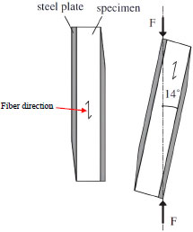
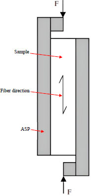
The shear force capacity of timber can be examined based on the method described in the European Standard EN 408 [24]. In brief, test timber samples are placed in two angled steel plates (ASPs) being loaded with two opposing forces 14° from the fiber direction. Fig. (1) shows the specimen and loading arrangement based on [24]. However, several studies using this method noted that the adhesive applied to attach ASPs to timber tends to slip, giving wrong shear force capacity values. According to Anderson and Odén [30], high-stress concentrations occur at the ends of ASPs under compression, which causes them to slip. They presented a modification of the European Standard EN 408 method, which is based on trying to equalize the stress concentrations. This was done by screwing the timber to ASPs instead of gluing, with which it was also easily possible to reuse ASPs for each test. The modified method is different, where the forces are applied along the fiber direction using ASPs that extend across the width of the test samples. The modified method is illustrated in Fig. (2). The reason for the changed setup was to reduce the forces that occur perpendicular to the fibers in the method by the European Standard EN 408 [5] and to obtain as a pure shear force in the timber as possible.
The capacity of the GIT rods depends very much on the correct execution. The main purpose of the glue in the GIT rods is to create a homogeneous connection between the glulam and rods. This is to effectively transfer and resist loads in a more effective way. The goal is to always ensure during the construction phase that the glue connections are not the weakest links in the joints, the timber should always break first. When choosing glue types, there are several factors that play important roles. Consideration must be given to both mechanical and geometrical aspects. Examples of this are the adhesion strength of the glue, the diameters of drill holes compared with the diameters of threaded rods, the thickness of the glue lines, and the drilling depths of threaded rods. All of these are considered so that the glue joints should not be the failing factor in the connection between the threaded rods and glued timber [31].
When threaded rods are placed in glulam beams that have been drilled to diameters exceeding the diameters of the rods, it is important that the glue has a good ability to fill the cavities. The hole diameter used in this research exceeded the diameters of the rods by 0.5 mm, which is described in Section 2 of this article. The epoxy glue is good at filling up these cavities, meaning that it is the timber that breaks first in such situations [32], and the glue provides a suitable connection between the glulam and rods.
2.2. Experimental Tests
2.2.1. Overview of Experimental Program
Forty samples categorizing into five different sample series with eight samples in each were provided for testing. The sample series are described below:
- Sample series 1 - unreinforced samples.
- Sample series 2 - samples reinforced with two GIT rods Ф6 at the IA of 45° to the fiber direction.
- Sample series 3 - samples split in the middle along the fiber direction and reinforced with two GIT rods Ф6 at the IA of 45° to the fiber direction.
- Sample series 4 - samples reinforced with two GIT rods Ф6 at the IA of 90° to the fiber direction.
- Sample series 5 - samples split in the middle along the fiber direction and reinforced with two GIT rods Ф6 at the IA of 90° to the fiber direction.
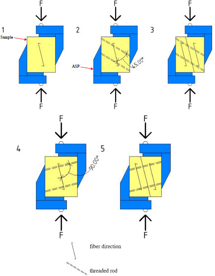
The glulam samples were from GL28cs. The samples were screwed into the two ASPs. The setup of the test sample series in ASPs is presented in Fig. (3). As can be seen from the figure, sample series 1 were only concerned with the capacity of glulam, therefore, no additional work processes had to be applied apart from drilling for attaching glulam to ASPs. The samples were tested for failure using a standard machine, Shimadzu Autograph AG-X. The measurements were carried out according to the European Standard EN 408 [24] for obtaining the shear force capacity of the samples. The test results were compared, which are reported in Section 3 of the current article.
2.2.2. Dimensions of Test Samples and Drill Diameters
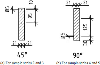
The dimensions of the test samples were considered as reported previously [26], which were 42×180×225 mm, and they were cut at an angle of 14° from the fiber direction. Fig. (4) elaborates on further details of the samples.
A preliminary study was done to investigate the choice of drill diameter. The purpose was to examine how the glue was distributed in the holes depending on their diameters. The examined test samples had hole diameters of 5 mm and 5.5 mm. The glue was introduced into the holes using a hose as described in Section 2.2.3. It was observed that the glue was well distributed along the entire 5 mm hole, which was better than the case with a 5.5 mm hole. Thus, the drill diameter of 5 mm was chosen as the best option.
2.2.3. Preparation of Test Samples and Testing
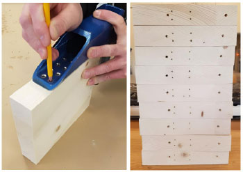
In order for all the drill holes to achieve the same placements, two drill rigs were made consisting of two joists, each 120×45 mm, which were then screwed together to stabilize the test samples. They were sawn to shape after the test samples at the angles of 45° and 90° ± 14° to enable drilling in the vertical direction. This was done to facilitate the drilling process while minimizing the risk of oblique and incorrect drilling. Fig. (5) indicates the drilling rigs.
(a) For drilling at IA of 45° from fiber direction.
(b) For drilling at IA of 90° from fiber direction.
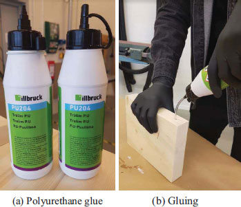
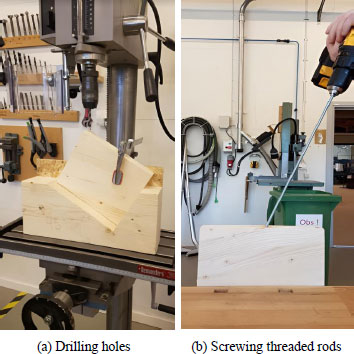
For sample series 2 and 4, the holes (5×315 mm) were drilled as displayed in Fig. (6). The polyurethane adhesive of the brand Illbruck (PU204) was used. Then, glue was fed into the drilled holes employing a hose (Fig. 7). The threaded rods with a diameter of 6 mm were screwed into the pre-drilled holes of the test samples, as shown in Fig. (8). The threaded rods were terminated 5-10 mm before the exterior sides. Then, four holes of 4.5×36 mm were drilled on each side for screw fixing to ASPs.
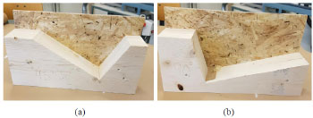
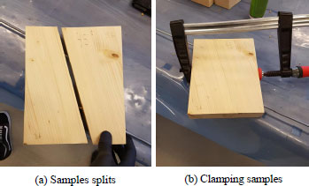
For sample series 3 and 5, drilling was done following the same procedure as for sample series 2 and 4. The samples were cured for a week before being split. The samples were sawed apart in their center line along the fiber direction, as depicted in Fig. (9), based on Fig. (3) for sample series 3 and 5. Both parts were then placed next to each other, and glue was applied in the holes. Afterward, the threaded rods were screwed into each glued hole carefully to have time to wipe off excess glue that seeped out of the holes. This was a critical point; no glue was allowed between two pieces of samples, as these series of tests would only examine the strength of the threaded rods. Then, the remaining parts of the two holes were filled with glue. The test pieces were placed against each other on a workbench so that the threaded rods entered the corresponding holes. A clamp was used to clamp the sample pieces in the correct positions until the threaded rods were fully screwed (Fig. 9). Fixing the samples to ASPs was conducted in the same way as for sample series 2 and 4.
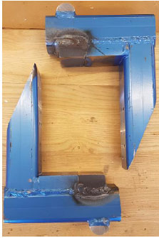
As the final step of sample preparations, all the samples were screwed to ASPs [26] with four screws on each side. ASPs were provided based on the approved method of the European Standard EN 408 [24]. ASPs are indicated in Fig. (10).
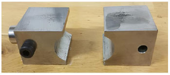
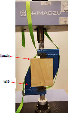
Steel joints were utilized to center the load in the test rig [26]. Fig. (11) elaborates on the loading joints. The attached glulam samples to ASPs were placed in the testing machine, as illustrated in Fig. (12). The used tension strap in the figure secured ASPs. All the sample series were tested under compression. The samples were loaded at a speed of 2 mm/min. The machine was connected to a computer that automatically recorded the measured data, such as forces and displacements in the machine's computer program, Trapezium X, during the tests. The machine could provide a speed range of 0.00005 mm/min to 1000 mm/min.
3. RESULTS AND DISCUSSION
The results obtained from the experimental tests are reported and discussed in this section. Figs. (13-17) present the force-displacement graphs and Table 1 summarizes the results. The different stiffnesses of the materials are believed to have resulted in different interactions between threaded rods and glulam, which have led to different capacity values for the reinforced test series. The average USFCs of the samples series 1-5 were obtained as 50.4 kN, 56.7 kN, 19.8 kN, 50.9 kN, and 13.2 kN, respectively. The force transfer took place internally in the GIT rod connections. The rod experienced the force as normal stresses, but the force transferred between the rod and glue was surface-dependent. The force was transferred as local normal compressive stresses at the threaded rods, which are generally superior to the smooth rods. Since the area of adhesion is maximized in the threaded rods and thus the degree of mechanical interlocking is enhanced, they are most frequently utilized in practice. Shear governs the load transfer between the adhesive layer and the timber as well as through the adhesive layer. The reinforced sample series 2 resulted in a 12.5% higher average USFC compared with sample series 1. This issue elaborates on the effectiveness of reinforcing glulam with the GIT rods at the IA of 45° to the fiber direction. However, reinforcing glulam with the GIT rods at the IA of 90° to the fiber direction in sample series 4 did not significantly enhance the average USFC compared with sample series 1, demonstrating that reinforcing glulam with the GIT rods at the IA of 90° to the fiber direction was not that helpful for glulam. This point signifies that the IA of 45° to the fiber direction is superior to the IA of 90°. This can be of great importance for projects in practice when reinforcing the glulam with GIT rods is under question.
The USFCs of the threaded rods investigated in both test series 3 and 5 resulted in low values. The reason for the low USFCs values can be explained by the fact that breakage did not occur in the threaded rods but occurred when the threaded rods in glulam loosened. This could be due to oblique drilling, oblique screwing of the threaded rods, or the use of an insufficient amount of glue, which might be sources of the low USFCs.
| Sample Series |
Average USFC (kN) |
Increased Average USFC Compared with Sample Series 1 (%) | Increased Interaction between Glulam and Threaded Rods Compared with Sample Series 1 | |
|---|---|---|---|---|
| (kN) | (%) | |||
| 1 | 50.4 | - | - | - |
| 2 | 56.7 | 12.5 | 6.3 | - |
| 3 | 19.8 | - | - | 31.8 |
| 4 | 50.9 | 1 | 0.5 | - |
| 5 | 13.2 | - | - | 3.8 |
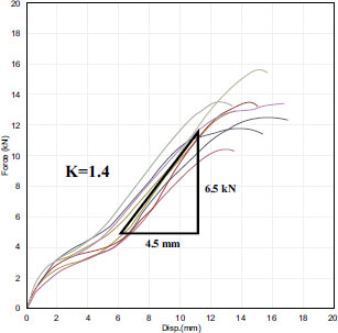
The USFCs’ curves of test series 5 probably arose when different failure modes occurred during the tests. The weak part of the curve between 2- and 6-mm displacement was probably due to the embedment strength of glulam being exceeded and deforming glulam. The threaded rods were then bent, which depended on their yield strength, giving the steeper curve after 6-mm displacement, as can be observed from Fig. (17).
In order to achieve good interaction between the glulam and threaded rods, the stiffnesses and E-modules of both materials need to be equivalent. In the elastic range, the graphs for the test series would follow a straight line. Average values were taken for the series and then a new line was drawn to examine the relationship between the force and displacement. The stiffness (K) was calculated using the following equation:
 |
where F and X are the force (kN) and displacement (mm), respectively. The obtained K values are reported in Figs. (13-17).
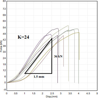
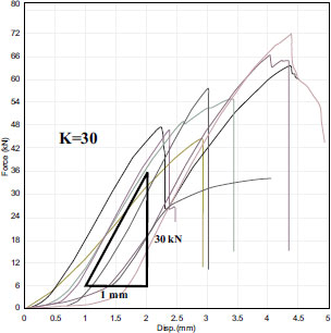
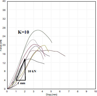
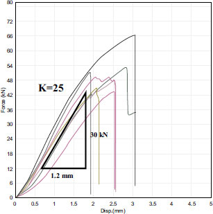
The same trends mentioned for the USFCs of the tested sample series 2 and 4 could also be observed for their stiffnesses. By reinforcing glulam with the GIT rods at the IA of 45° to the fiber direction in sample series 2, the stiffness was increased 25%. Whilst, reinforcing glulam with the GIT rods at the IA of 90° to the fiber direction did not considerably improve the stiffness. This point again emphasized the effectiveness of reinforcing glulam with the GIT rods at the IA of 45° to the fiber direction.
The interaction was also studied in this research to investigate how the GIT rods and glulam interacted with each other in the reinforced test series. The interaction (%) was calculated according to the following equation:
 |
As can be seen from Table 1, the interaction between the glulam and GIT rods was achieved as 31.8% and 3.8%, respectively, for reinforcing glulam at the IA of 45° to the fiber direction and at the IA of 90° to the fiber direction. This issue clarifies the interaction effect of reinforcing glulam at the IA of 45° to the fiber direction compared with reinforcing glulam at the IA of 90°. Moreover, the method with the GIT rods demonstrated the possibility of increasing the USFCs in glulam.
Despite the mentioned structural advantages of reinforcing glulam using the GIT steel rods, since glulam and steel have different longitudinal expansion and contraction coefficients, the composite glulam-steel material expands differently at varying temperatures and humidity levels. Hence, this type of solution may not be suitable for outdoor climates, where large temperature and humidity changes occur. This can give rise to cracks in glulam.
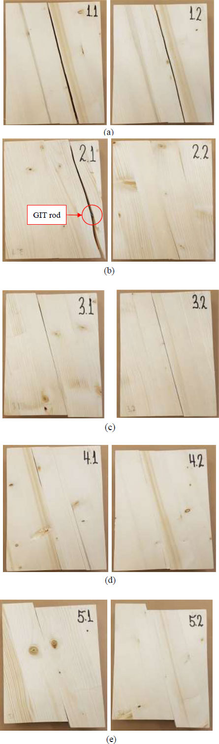
Fig. (18) displays the typical fractures of the tested samples. The unreinforced and reinforced sample series demonstrated different types of fractures during the tests. Complete and sudden fractures occurred in the unreinforced samples. Brittle failure also occurred in the reinforced samples, but the GIT rods prevented the complete failure of the samples by holding the pieces together after failure. This issue showed that the GIT rods not only contributed to an increase in the USFC but also prevented the complete failure of the samples.
CONCLUSION
This experimental research investigated how the USFC of glulam would be affected if it were reinforced with the GIT rods. Also, the interaction between the glulam and GIT rods was studied. The glulam samples were experimentally examined under different conditions, such as unreinforced and reinforced with the GIT rods at two different IAs of 45° and 90° to the fiber direction. The experimental program included testing forty glulam samples, which were categorized into five different series with eight samples in each series. The tests were done for failure using a standard machine. The results were obtained as force-displacement graphs. The stiffness of the samples and interaction between the glulam and GIT rods were calculated as well. A total of 12.5% increase in the average USFC of the samples was reported thanks to its reinforcing with the GIT rods at the IA of 45° to the fiber direction, while the average USFC of the samples was enhanced inconsiderably by its reinforcement with the GIT rods at the IA of 90° to the fiber direction. The stiffness of the samples was increased by 25% by reinforcing with the GIT rods at the IA of 45° to the fiber direction, whilst there was an insignificant enhancement of the stiffness for glulam with the GIT rods at the IA of 90° to the fiber direction. Furthermore, the interaction between the glulam and GIT rods was obtained at 31.8% and 3.8% for the samples with reinforcing at the IAs of 45° and 90° to the fiber direction, respectively. The results of this study demonstrated that the diagonal force of reinforcement using threaded rods in the glulam samples could increase the capacity of glulam. The method with the GIT rods indicated the possibility of increasing the USFC of glulam. As shear force strengthening of glulam is still a relatively unexplored area, there are further opportunities for future studies. Unglued and glued threaded rods can be studied to assess the influence of glue on the USFC. Furthermore, different adhesive types and adhesive methods can be examined to optimize their impact on the USFC.
LIST OF ABBREVIATIONS
| ASP | = Angled Steel Plate |
| GIT | = Glued-in Threaded |
| USFC | = Ultimate Shear Force Capacity |
| IA | = Inclination Angle |
CONSENT FOR PUBLICATION
Not applicable.
AVAILABILITY OF DATA AND MATERIALS
All the data and supportive information are provided within the article.
FUNDING
None.
CONFLICT OF INTEREST
The authors declare no conflict of interest, financial or otherwise.
ACKNOWLEDGEMENTS
Declared none.

