All published articles of this journal are available on ScienceDirect.

Design of Steel Exoskeleton Equipped with BRBs for Seismic Upgrading of RC Frames
Authors Info & Affiliations
Abstract
Background:
The main part of the Italian building stock was mainly erected between ‘70s and ‘80s of the previous century. Hence, existing RC buildings present structural deficiencies because were designed according to old standards and often only considering gravity loads.
Objective:
The goal is to evaluate the seismic performance of these structures and compare it to the minimum standards required by current legislation.
Methods:
To achieve this goal, first, a building with RC framed structure has been designed according to the codes and the practice in force at the time of construction. From this building two case study frames have been derived considering different mechanical properties of the concrete. Then, the addition to the existing RC building of a steel exoskeleton equipped with BRBs is proposed for seismic upgrading of these structures and the effects of this intervention on the seismic performance of the frames are investigated. A design method of seismic upgrading interventions by exoskeleton and BRBs is developed and applied to the two case study frames. The design method is calibrated determining the seismic response of the upgraded frames by means of non-linear dynamic analyses.
Results:
The parametric analysis allowed the identification of the combinations of the parameters that lead to the achievement of the performance objectives at Near Collapse and Significative Damage limit states. Both the frames designed according to this combination of design parameters show suitable seismic performance for both considered limit states.
Conclusion:
Finally, the combination of the parameters ruling the design method is determined as the most economical among those that allow the fulfilment of the requirements at NC and SD limit state.
1. INTRODUCTION
Even if many regions of the world are extremely exposed to seismic activity, it does not imply that the building stock of those areas is able to withstand horizontal actions due to earthquakes. For instance, in Italy, due to the continuous evolution of the seismic zonation and seismic code, the majority of the existing buildings do not comply with current seismic codes, as they were designed for gravity loads in areas that today are classified with a high level of seismic hazard. In fact, according to the latest census data available in Italy, 3.5 million residential buildings, out of a total of 12 million, are Reinforced Concrete (RC) structures built between the 70s and 80s of XX century, when no seismic codes were in force and a few areas were considered seismic prone [1]. Unfortunately, recent severe earthquakes dramatically demonstrated that RC structures designed before the enforcement of modern seismic codes are generally vulnerable to seismic excitation and have led to terrible effects: collapse of buildings entailed high costs in terms of human lives and economic losses [2].
Existing buildings often have deficiencies related to the design and execution process, such as poor materials (low quality concrete) or structural members mainly orientated along one direction. Today, in addition to high CO2 emissions and excessive energy consumption, they have evident signs of decay and poor living comfort conditions. Since these buildings do not meet the performance requirements imposed by current legislation that guarantee the necessary safety levels, it is important to define methods for their seismic upgrading. Furthermore, methods aimed at improving the structural, architectural and energy deficiencies of the buildings should be preferred over others. Indeed, traditional interventions that solve only one of these deficiencies are inefficient, because they are not based on a circular and sustainable economy.
The addition to the existing RC frame of a steel exoskeleton equipped with Buckling Restrained Braces (BRBs) is here proposed as seismic upgrading technique. The features of the behaviour of BRBs, which have been deeply investigated [3-7], make this device attractive for seismic protection of buildings [8-11]. In particular, BRBs provide the RC frame with additional stiffness, strength and energy dissipation capacity and thus reduce the storey drift demand. If properly distributed along the height of the building, they can also avoid drift concentration at a few stories and promote a favourable and dissipative collapse mechanism. The use of the exoskeleton has the advantage of being versatile and minimally invasive. In fact, it does not need local demolition and avoids the relocation of tenants, as the entire intervention takes place outside the building. These aspects make the seismic upgrading by steel exoskeleton economically competitive and affordable for residential dwellings that need seismic retrofit. Furthermore, the steel exoskeleton ensures the maintenance of the deformation capacity of the RC columns, because the axial force acting on the BRBs is transmitted to the steel columns of the exoskeleton, while the original RC columns are not further aggravated. Recent researchers demonstrated that structural rehabilitation by means of external exoskeleton offers the chance to integrate also devices or technologies for the energy upgrading of such structures. It can also be integrated with an architectural restyling of the building in the framework of the regulations of the local authorities [12, 13]. In fact, it can become the support for a double skin capable of improving energy performance. At the same time, it can change the exposure class of the environment, increase the durability of the construction and extend its useful life. These aspects may encourage the owner to implement the upgrading interventions and facilitate the achievement of the approval by the local authorities. The use of exoskeletons is an effective intervention strategy in order to increase the resilience of the built environment in a sustainable and reversible way, redeveloping the existing building stock [2]. In this regard, a very efficient solution of integrated façade with BRB was presented by Takeuchi et al. [13]; they proposed the use of an integrated façade that includes glass, grid and steel braces. This multi-skin system increases the performance, both seismic and thermal, of the building. In particular, BRBs are used to reduce the displacement required by earthquakes to acceptable values. Grid and glass mitigate the temperature inside the building in both winter and summer.
This paper develops a displacement-based design method to size the steel exoskeleton equipped with BRBs necessary for the upgrading of RC buildings according to current seismic standards. The target of this method is defined in terms of local response, which is tuned at all stories with the capacity corresponding to a target limit state. A drift requirement and a ductility requirement rule the design of the BRBs, while the columns of the steel exoskeleton are sized based on stiffness and strength requirements. The evaluation of the drift demand is based on the equal-displacement rule and it is determined by the elastic analysis. The pushover analysis is also incorporated within the design procedure and is run to evaluate the drift capacity and the internal forces on the elements of the RC frame. The ruling parameters of the design method are calibrated in order to fulfil the two performance objectives stipulated in Eurocode8 (EC8) [14] for strong ground motion, i.e. Near Collapse (NC) and Significant Damage (SD) performance objectives.
2. SEISMIC PERFORMANCE OF THE CASE STUDY FRAMES
RC buildings constructed in Italy between the 70s and 80s of XX century are characterized by typical seismic structural deficiencies, such as beams and columns orientated along one direction or low lateral stiffness and strength. As a consequence, the case study considered here aims to be representative of this kind of buildings. Hence, it is designed according to a procedure which is based on old Italian standards [15-17] and simulates the design practice followed before seismic codes entered into force. Particularly, the case study building is designed considering gravity loads (GL) only. In the case of seismic upgrading of real RC buildings, the simulated project is not always necessary as the geometrical features, the characteristics of materials and constructive details are usually provided by in-situ survey and material campaign tests or, if available, by the original design documents. The goal is to evaluate the seismic performance of this structure and compare it to the minimum standards required by current legislation.
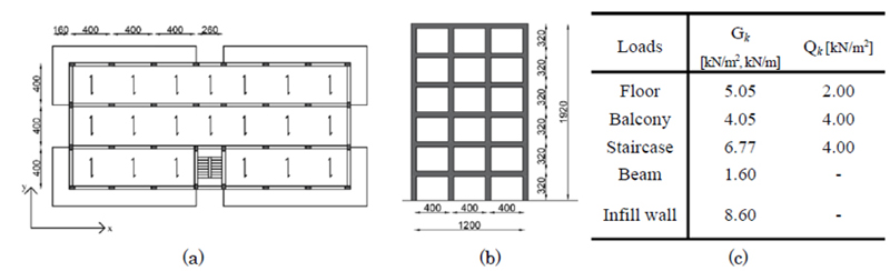
The analysed GL frame belongs to the six-storey high building characterized by a rectangular plan layout shown in Fig. (1a), which is symmetrical with respect to y-axis. Four frames are arranged along the x-direction and composed by seven spans each. These frames provide the structure with a good lateral stiffness with respect to the seismic action along the x-direction. Instead, the y- direction presents two frames composed of three spans at the two sides of the plan, and two frames composed of only one span at the sides of the staircase (Fig. 1a and 1b).
The design internal forces of structural members are evaluated considering gravity loads only: dead loads, including self-weight of structural and no-structural elements, and live loads [18]. Their values are reported in Fig. (1c).
Beams and columns are designed according to the allowable stress method [16], that was the design procedure commonly used in the seventies of XX century. In this regard, the characteristic compressive cubic strength Rck is assumed equal to 25 MPa (corresponding to cylinder strength fck equal to 20 MPa) for concrete. A steel grade Feb38k with a characteristic yield stress fyk=375 MPa is used for reinforcement. The values of allowable stresses are equal to 8.5 MPa and 215 MPa for concrete and steel reinforcement, respectively.
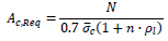
The minimum required cross section area of the column Ac,Req is calculated by the following equation:
 |
(1) |
where  is the allowable stress of concrete, n is the homogenization coefficient for steel rebars assumed equal to 10 and ρl is the ratio of the longitudinal rebar area As to Ac,Req, here assumed equal to the minimum value required by the code (0.006).
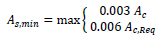
The area As of the longitudinal rebars of columns must be not smaller than the minimum value:
 |
(2) |
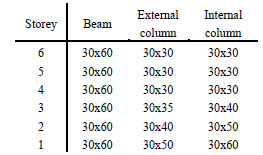
Since the y-direction results to be the weakest one of the designed building, the external frame in the y-direction is considered in the analysis. Fig. (1b) shows the geometrical scheme of the considered frame, while the cross sections of structural members obtained from the design procedure are summarized in Table 1.
| Storey | External Column | Internal Column | Storey | Section A-A | Section B-B |
|---|---|---|---|---|---|
| 6,5,4 |  |
 |
All |  |
 |
| 3 |  |
 |
 |
||
| 2 |  |
 |
 |
||
| 1 |  |
 |
|||
| Parameters | Concrete | Steel for Rebars | BRBs | |
|---|---|---|---|---|
| GL1 | GL2 | |||
| Compressive strength | fcm=29 MPa | fcm=20 MPa | - | - |
| Yield stress | - | fym=400 MPa | fym=100-235 MPa | |
| Young's modulus | Ecm=30280 MPa | Ecm=27085 MPa | Es=210000 MPa | Es=210000 MPa |
| Poisson's ratio | v=0.5 | v=0.3 | v=0.3 | |
In order to increase the set of case studies, two frames were considered and both derived from GL frame: frame GL1 is totally consistent with the frame GL previously described, in terms of mechanical properties of materials, loads and seismic weight, size of structural members. The other case study, frame GL2, differs only for the compressive strength of concrete, which is assumed lower than that considered in design (fck=12 MPa instead of 20 MPa). Frames GL2 simulates the existing structures that were realized using concrete with mechanical properties lower than those prescribed by the design, or it could be representative of buildings that suffered from intensive deterioration phenomena.
2.1. Numerical Model
The numerical model was developed in OpenSees [19]. In order to analyse the non-linear response of the structures a two-dimensional numerical model, with masses concentrated at the floor levels, was developed. The floor mass is assumed as a percentage of the total mass of the deck. In particular, along the y-direction, the outermost frames are stiffer than those close to the staircase, so they resist a larger seismic force. Hence, it was assumed that 60% of the floor mass is supported by the external frames (30% of the total mass for each frame).
To simulate the effect of the concrete slab, a rigid diaphragm constraint is assigned to all the nodes of the same floor, so that they cannot have relative displacements. In the analysis, gravity dead loads and live loads are assigned. A Rayleigh viscous damping is used and set at 5% for the first and third mode of vibration.
To include P-∆ effects, a leaning column was added. Gravity loads applied on these columns are equal to the weight of the numerical model minus the loads applied directly to the RC frames.
A member-by-member modeling and the “Beam With Hinges Element” is used to model beams and columns. This type of element is constituted by an elastic central part and a plastic hinge at each end. The length of the plastic hinges is here assumed equal to the depth of the cross section. Fibre cross sections are assigned to the plastic hinges and include both concrete and steel rebars. The concrete part of the cross section is subdivided into fibres having 5 mm depth and width equal to the width of the cross sections; the Mander constitutive law (“Concrete04” uniaxial material) is assigned to these concrete fibres. Single fibres enclosed in the cross section are used to model rebars with an elasto-plastic with strain kinematic hardening constitutive law (“Steel01” uniaxial material). The characteristics of materials used for the numerical model are summarized in Table 2 for the analysed frames.
The fibre modelling of the sections, combined with the hypothesis of a rigid diaphragm, involves the presence of a fictitious axial force acting on the beams [20]. To prevent such problem, a buffer element is introduced as a “zero length element”. It is characterized by a very low axial stiffness. Therefore, it allows the elongation of the beam and avoids the development of axial force acting on it. At the same time, a high shear and flexural stiffness of the buffer element ensures the continuity of the beam-column joint and the transfer of shear force and bending moment.
2.2. Seismic Performance of Examined Frames
The seismic performance of the two frames is evaluated in order to determine if the upgrading intervention is necessary. Seismic capacity is evaluated through Incremental non-linear Dynamic Analysis (IDA) as the maximum PGA that can be sustained before exceedance of the target limit state. A suite of 10 artificial ground motions, compatible with the EC8 elastic spectrum for soil type C and characterized by 5% damping ratio and reference peak ground acceleration for soil type A equal to 0.35g, is adopted as the reference seismic input. Each ground motion is characterized by a total duration of 30.5 s. Details about the envelope intensity function may be found in [21]. The set of ground motion is scaled for increasing values of PGA in step of 0.05 g for frame GL1 and the minimum considered PGA is equal to 0.05 g. For frame GL2, the minimum considered value of PGA is 0.025 g and the ground motions are scaled for increasing values of PGA in step of 0.025 g.
Two limit states defined by the Italian seismic code for existing buildings are here considered: the near collapse (NC) limit state, corresponding to a PGA equal to 0.45 g and a probability of exceedance of 5% in 50 years and the significative damage (SD) corresponding to a PGA equal to 0.35 g and a probability of exceedance of 10% in 50 years. The seismic capacity of both frames is compared with the respective minimum values imposed by the NTC2018.
The seismic performance of the analysed frames is evaluated in terms of storey drift angle demand (∆/H) and demand to capacity ratios. The drift demand ∆ is the displacement which the structure is subjected as a function of a target limit state and H the inter-storey height. These demand to capacity ratios are evaluated in terms of drift (∆/∆LS), chord rotation (ϑ/ϑLS) and shear (VEd/VRd) where VEd is the storey shear force the and VRd is the storey lateral strength. For a given excitation level, the maximum values of the response parameters are evaluated for each ground motion and then averaged over the ten inputs.
The storey drift capacity of each storey is evaluated as a function of the chord rotation capacity of the columns. In particular, the chord rotation capacity at the considered limit state ϑLS is evaluated for all the columns of each storey, and the minimum value is used to calculate the drift capacity ∆LS of the relevant storey:
 |
(3) |
where Lcl is the clear length of the columns.
In particular, the chord rotation capacity is assumed equal to ϑum calculated according to the equation provided by EC8 [14] for the NC limit state. The shear strength is calculated according to Eurocode2 [22].
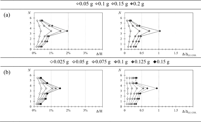
Fig. (2) shows the heigthwise distribution of the storey drift angle demand and the drift demand to capacity ratio related to the NC limit state for frames GL1 (Fig. 2a) and GL2 (Fig. 2b) under increasing values of PGA. Results are shown for frame GL1 and GL2 up to PGA equal to 0.20 g and 0.15 g, respectively. In the case of larger values of PGA, in fact, dynamic analyses concluded prematurely in more than 50% of the accelerograms due to numerical instabilities, which can be identified as collapse of the structure in occurrence of the related accelerograms. Both GL1 and GL2 frames show a drift concentration at the fourth storey, which becomes more significant for increasing PGA. The GL2 frame experiences the worst seismic performance, the largest storey drift angle and the largest number of accelerograms for which numerical instabilities occurred. The analysis of the drift demand to capacity ratio shows that the NC limit state of the GL1 and GL2 frame is attained for a PGA close to 0.20 g (Fig. 2a) and 0.15 g (Fig. 2b), respectively.
The demand to capacity ratio in terms of chord rotation is determined for columns and beams. The verification is fulfilled when the demand to capacity ratio is lower than 1. Fig. (3) shows the heightwise distribution of the demand to capacity ratio (ϑ/ϑLS of columns and ϑ/ϑLS of beams) and shear check VEd/VRd for frame GL1 and GL2, respectively. Regardless of the considered limit state, frame GL1 shows a concentration of damage and a soft storey collapse mechanism. Indeed, plastic hinges occur mainly at the ends of columns of the fourth storey, where the demand to capacity ratio is the largest along the height and close to unity for a PGA equal to 0.20 g. Furthermore, beams remained almost elastic. Note that the results obtained for columns in terms of drift (Fig. 2a) are similar to those expressed in terms of chord rotation (Fig. 3a), even though they are moderately more conservative. The same conclusions can be observed also for frame GL2, which almost exceeds the capacity for a PGA of 0.15 g. The shear force demand of columns never exceeds the capacity.
Both frame GL1 and GL2 exhibited significant structural deficiencies did not meet the minimum requirements of EC8 for NC limit state and need to be seismically upgraded.
3. MATERIALS AND METHODS
The proposed design method is implemented within an iterative procedure which determines exoskeleton components (BRBs and columns) to provide the RC frame with the additional stiffness and strength needed to withstand the expected earthquake without exceeding the target limit state. For instance, the NC or SD limit state defined in EC8 under relevant earthquake excitation level can be considered. The purposes of this method are to improve the dissipative capacity of RC frames, and ensure a dissipative collapse mechanism, characterized by a uniform distribution of the demand to capacity drifts.

Prior to the design procedure, it is fundamental to know the geometrical and mechanical features of the structure. Indeed, this information is needed for the seismic assessment of the structure, which is always performed before the design of the upgrading, regardless of the type of intervention, to understand if the building is seismic-deficient or not. The same geometrical and mechanical features of the structure, such as building height and fundamental period of vibration of the structure, are necessary for the sizing of the intervention.
The design procedure is based on the fulfilment of four requirements: (1) the storey drift of the RC frame demanded by the earthquake must not exceed the defined design storey drift, (2) the ductility demand of BRBs must not exceed their ductility capacity, (3) instability of steel columns of the exoskeleton and (4) their excessive deformation must be prevented.
3.1. Evaluation of Capacity
The drift capacity of the RC frame ∆LS is defined as the storey drift corresponding to the attainment of the target limit state. The storey drift capacity of each storey is evaluated by means of the chord rotation of the columns. In particular, the value of the chord rotation depends on the geometrical and mechanical characteristics of the cross section and on the axial force of the considered column. The axial force is provided by the pushover analysis at the step when the drift demand is equal to the drift capacity. The chord rotation is evaluated for all the columns of each storey, and the minimum value is used to calculate the drift capacity ∆LS, which is given by Eq. (3). The design storey drift ∆d at each storey is assumed as a percentage λ of the storey drift capacity ∆LS to take into account some concentration of storey drift that may occur during the response. Since BRBs are inserted within the external exoskeleton, the axial force they transmit is carried out by the steel columns and, therefore, the drift capacity of the RC frame is not reduced.
3.2. Design of BRBs
The design of the BRBs is based on two steps whose purpose is to determine the axial stiffness, and consequently the equivalent area AEq, and then the yield strength NBRB,y.
The axial stiffness of the BRBs is evaluated as a function of the drift demand and capacity of the RC frame. In fact, if the drift demand overcomes the design storey drift, BRBs have to provide the lacking stiffness.
The drift demand Δ is determined by a linear method of analysis, considering the elastic response spectrum and PGA corresponding to the assumed seismic excitation level. The use of a linear method of analysis is based on the equal displacements rule. This approach is deemed suitable because the drift demand is expected to be rather uniform along the height owing to the coupling with the exoskeleton equipped with BRBs that should lead to an almost uniform yielding along the height of the building.
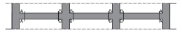
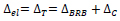
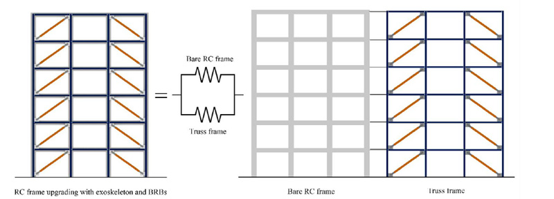
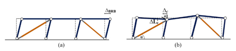
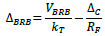
The structure composed of the RC frame and the steel exoskeleton with BRBs can be schematized as two frames connected in parallel (Fig. 4). The elastic drift ∆el of the whole structure is equal to the drift ∆T of the truss frame that simulates the exoskeleton. The latter is the sum of two contributions: the drift ∆BRB caused by the axial deformations of the BRBs (Fig. 5a) and the drift ∆C due to the axial deformations of the columns (Fig. 5b).
 |
(4) |
In particular, the drift ∆C is calculated considering that only columns undergo axial deformation, while BRBs maintain the original length:
 |
(5) |
where α is the inclination of the BRBs with respect to the beam longitudinal axis; and ∆LC is the length variation of the column evaluated by linear analysis.
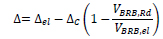
The value of ∆el obtained by linear analysis is modified to take into account two issues. The first is that the contribution to ∆el given by the axial deformation of the columns is greater than the real value. This happens because the modal analysis does not take into account yielding of the structural elements, which can experience deformations greater than those that would actually occur. The actual drift demand Δ is determined by adding to ∆BRB (∆BRB = ∆el -∆C) the drift equal to  , which represents the fraction of ∆C that contributes to the drift before the yielding of the elements:
 |
(6) |
The elastic storey shear force VBRB,el is equal to the storey shear of the BRBs determined by the linear analysis, the lateral resistance VBRB,Rd provided by BRBs is calculated by the pushover analysis at the attainment of the target limit state.
The second issue is that the equal displacement rule does not apply when fundamental period T1 of the structure is smaller than the corner period of the spectrum TC. Therefore, if T1 is less than TC the displacement demand is multiplied by the correction factor CR:
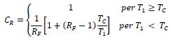 |
(7) |
Note that RF is the force reduction factor given by the ratio of the VBRB,el to VBRB,Rd.
The axial stiffness of the BRBs is determined so that the truss frame provides the structure with the stiffness necessary to satisfy the requirement on drifts, according to the following equation:
 |
(8) |
The required lateral stiffness kReq is calculated as the ratio of the storey shear force determined by the elastic analysis over the design storey drift ∆d. The lateral stiffness of the bare RC frame kBF is evaluated as the ratio of the elastic shear force carried by columns of the storey over the demanded storey drift ∆.
The displacement ∆BRB produced by the axial deformation of BRBs is evaluated as the difference between the drift caused by the shear carried by BRBs (VBRB) and the drift caused by the axial deformation of the columns:
 |
(9) |
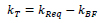
The additional stiffness that BRBs have to provide to fulfil the requirement on storey drift is determined as:
 |
(10) |
At the first iteration kBRB is equal to kT. Given the value of kBRB, the axial stiffness kBRB,ax of the single BRB is determined as follows:
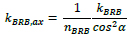 |
(11) |
Where nBRB is the number of BRBs to be included in each storey. From the axial stiffness it is possible to define the equivalent area Aeq,BRB of the BRB cross section:
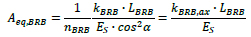 |
(12) |
Once that the equivalent area of BRBs is evaluated at each storey, the first step of the design is concluded. However, note that the insertion of BRBs increases the frame stiffness and causes a change in terms of seismic response. The additional stiffness provided by the BRBs may no longer be sufficient. For this reason, the procedure must be performed iteratively and a new modal analysis of the structure is required. The convergence of the design is attained when the displacement requirement ∆ < ∆d is satisfied at all storeys.
In the second step, the yield strength NBRB,y of BRBs is determined so that the requirement on ductility demand of BRBs is fulfilled, i.e. the ductility demand of BRB at the target limit state must not exceed its ductility capacity.
The ductility demand of the BRB is evaluated as the ratio of the drift demand caused by the elongation of the BRB at the target limit state ∆BRB,max over the drift demand corresponding to the yielding of BRBs ∆BRB,y
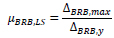 |
(13) |
The drift ∆BRB,max is calculated by subtracting the drift caused by the axial deformation of the columns from the drift demand ∆ and scaling the result according to the following equation:
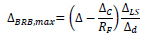 |
(14) |
The drift ∆BRB,y corresponding to yielding of BRBs can be calculated as function of the axial elongation of BRB at yielding ∆lBRB,max and the corresponding yield strength NBRB,y:
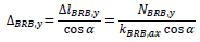 |
(15) |
From the equation of (13-15) the yield strength NBRB,y is evaluated so that the ductility demand µBRB is equal to the ductility capacity µBRB,LS:
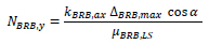 |
(16) |
The inserted BRBs modify the lateral stiffness and strength of the structure itself. For this reason, a pushover analysis is performed again to update the values of ∆LS, ∆d and VRd. This second macro - iteration is repeated until the obtained BRBs are the same of those obtained in the previous iteration.
3.3. Design of Columns of the Exoskeleton
Beams are connected to the RC deck, which are axially inextensible, and do not sustain forces or deformations. Connections between all the members of the exoskeleton are supposed to be pinned at their ends. Hence, columns experience only axial force and axial deformations. Furthermore, columns of the steel frame must be designed as non-dissipative elements. Therefore they must withstand the maximum force transmitted NEd,max by the dissipative elements, i.e. BRBs, considering the overstrength and strain hardening effects, both in tension and compression:
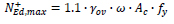 |
(17) |
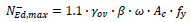 |
(18) |
where γov is the steel overstrength factor, Ac is the core area of BRB, fy is the yield strength of BRB, β and ω are the compression and tension strength adjustment factors, respectively. In particular, β is assumed equal to 1.1 and ω is calculated by means of the following relation:
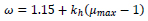 |
(19) |
where kh is the post-yield stiffness ratio and is set equal to 3.16% [22]. The force acting on each column is evaluated as the vertical component of the maximum compressive strength of the BRBs:
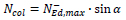 |
(20) |
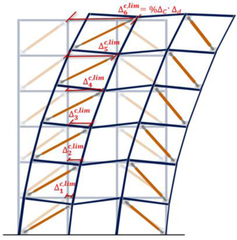
Note that, if the cross sections of columns sized according to the force transmitted by BRBs have small cross sections, columns may undergo large deformations. To prevent such large axial deformations of columns, a limit on the storey drift caused by the axial deformation of the columns is imposed (∆ic,lim). The value ∆topc,lim of top storey is set as a fraction %∆C of the drift capacity ∆LS of the top storey. The limit value ∆ic,lim of each intermediate storey is determined considering that ∆topc,lim, must be equal to the sum of the ∆ic,lim of the storeys below. In this way the limit value of the displacement ∆ic,lim is less than the percentage of the relative drift capacity ∆LS at each storey. At each storey there are two columns, the one at right and the one at left of BRBs, that undergo axial deformations, except for the first storey where only one column deforms, because the other one is fitted to the ground. So the deformation of each column is:
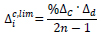 |
(21) |
n being the number of storeys.
The cross section of columns of the first storey A1Col,Dx can be determined as a function of the axial deformation of column ΔL1Col, the maximum axial force  acting on column and the length of the steel column L1Col:
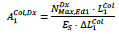 |
(22) |
Assuming the variation of the angle α is very small, the parameter ΔL1Col can be calculated with respect to the ∆1c,lim at first storey as follows:
 |
(23) |
From the second storey on, the axial deformation of the columns of the relevant storey depends also on the axial stiffness, and therefore on the area, of columns of the lower stories.
Hence, at an i-th storey, the axial deformation of column is evaluated as:
 |
(24) |
The factor 2 at numerator indicates that there are two columns that contribute to the floor drift. The area of the columns at the i-th storey is determined as:
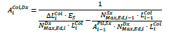 |
(25) |
where  is the maximum axial force on the column of the i-th storey at the right end of the bracing,
  is the maximum axial force acting on the column of the i-1-th storey at the left end of the bracing, LiCol is the length of the steel column at i-th storey;
  is the length of the steel column of the i-1-th storey,
  is the area of the column at the storey below previously calculated;
  is the area of the column of the i-th storey to be calculated.
3.4. Iterative Procedure
The design procedure develops into two macro-steps: the first one aims at defining whether the retrofit intervention is needed or not; the second step leads to the definition of the geometrical and mechanical features of the exoskeleton members, particularly BRBs and columns (Fig. 7).
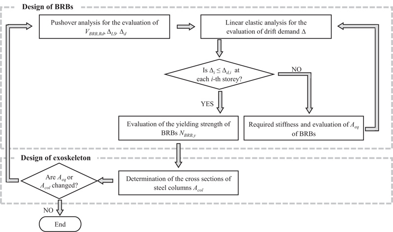
The first step starts with a pushover analysis, which is necessary for the evaluation of the lateral resistance of the structure VRd, the storey drift capacity at the target limit state ΔLS and the design storey drift Δd. The elastic drift demand Δel is evaluated by a linear analysis and the drift demand Δ is determined at each storey as described in Section 3.2. Hence, at each storey, the drift demand is compared to the design storey drift and if Δ > Δd the equivalent area of BRBs is sized so that they can provide the required lateral stiffness. Since the insertion of braces modifies the lateral stiffness, the linear analysis is repeated with the upgraded structure and the new drift demand is compared to the design storey drift.
4. RESULTS AND DISCUSSION
A set of RC frames upgraded by steel exoskeleton with BRBs is designed considering several combinations of λ and %∆C and, to evaluate the optimal values of these parameters, a parametrical analysis is carried out. Hence, the seismic response of the frames is determined by non-linear dynamic analysis. The set of 10 artificial accelerograms defined in Section 2.2 is scaled to the PGAs for soil type A equal to 0.45 g and 0.35 g, and these accelerograms are used for the verification of NC and SD limit states, respectively. The results of the numerical investigation are used to find out the retrofit solutions that allow the fulfilment of all the verifications. Among these, the optimal combination of λ and %∆C is identified as that corresponding to the exoskeleton with minimum size of the members [23].
4.1. Design and Numerical Model of the Analysed Frames
An external steel exoskeleton equipped with diagonal BRBs is used for the seismic upgrading of the RC frames described in Section 2. BRBs are embedded in the first and third spans of the steel frame, which has the same geometrical scheme of the existing RC frame and is linked to it at floor levels. The design method presented in Section 3 is applied to size the members of the steel exoskeleton. The NC limit state is assumed as target limit state, the seismic excitation level is the one associated with a probability of exceedance of 5% in 50 years and the ductility capacity of BRBs is assumed equal to 25.
The design of the seismic upgrading intervention is carried out considering several combinations of λ and %∆C. A previous study [24] carried out on frames upgraded by inserting BRBs within the RC frame recommended the use of λ=0.6. Based on this, the value λ=0.6 is included in the parametrical investigation. Furthermore, the values λ=0.8 and 1.0 are also considered to ascertain if the greater effectiveness of the exoskeleton with respect the simple insertion of BRBs within the RC frame may allow the use of a more relaxed value of this parameter. Finally, three values of the parameter %∆C are considered: 0.1, 0.15 and 0.20. It is important to remember that all the retrofit solutions are designed without considering the P-∆ effects. However, they are taken into account during the validation analyses.
The numerical model of the bare RC frame described in Section 2.1 is expanded introducing the elements that replicate the members of the exoskeleton. Steel columns of the exoskeleton are modelled as elastic beam-column elements because these members are designed to remain elastic during the ground motion. BRBs are modelled by the “NonlinearBeamColumn” of OpenSees. The cross-section area of BRBs is assumed constant along the element and equal to the equivalent area Aeq that reproduces the same axial stiffness of the steel core of the BRB. The cyclic behaviour of the BRB is simulated by the uniaxialMaterial “BrbDallAsta” formulated by Zona and Dall’Asta [25] as implemented in OpenSees by Rossi [26]. This material is able to replicate both kinematic and isotropic hardening that characterises the cyclic response of BRBs. The post-elastic stiffness due to kinematic hardening is assigned equal to 3.16% of the initial elastic stiffness [27] while the isotropic hardening is assumed to be responsible of an increase of yield strength equal to 15% of the initial value; the initial yield strength of the BRB material is defined by the equivalent yielding strength fy,eq calculated in design. In order to simulate the presence of the deck, the nodes of the same floor are constrained to have the same horizontal displacement.
4.2. Obtained Results
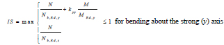
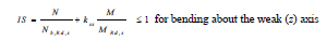
The results of the numerical investigation are processed to assess the exceedance of the NC and SD limit states for the relevant seismic excitation levels. Members of the RC frame are verified in terms of shear force of columns and chord rotation of beams and columns and the verification is quantified by the same performance indexes used in Section 2.2: shear force demand (VEd) to resistance (VRd) ratio and chord rotation demand (ϑ) to capacity (ϑLS) ratio. The attainment of instability and yielding of the columns of the steel exoskeleton is checked as well as the exceedance of the ductility capacity of BRBs. Since columns are subjected to combined axial compression N and bending moment M about one of the principal axes of the cross-section, it is assumed that member instability occurs when the Index of Stability (IS) determined by the two following equations is larger than 1:
 |
(26) |
 |
(27) |
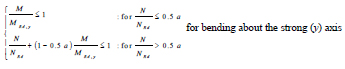
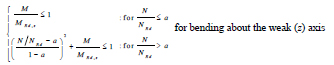
In Equations (26 and 27), Nb,Rd,y, Nb,Rd,z, MRd,y and MRd,z are the buckling and the moment resistances about the strong and the weak axis, while kyy and kzz are the interaction factors calculated according to Method 2 given in Annex B of Eurocode3 [28]. Similarly, it is assumed that yielding of columns occurs when the Index of plastic Resistance (IR) exceeds unity:
 |
(28) |
 |
(29) |
Equations (28 and 29) are derived from the resistance criteria stipulated by Eurocode 3 for the verification of wide-flange cross-sections subjected to combined bending moment and axial force. In these equations, NRd is the plastic resistance to axial force and a is the ratio of web area to gross area of the cross-section. The verification of BRBs is associated to the ductility demand (μBRB) to capacity (μBRB,LS) ratio, where μBRB,LS is equal to 25 and 19 at NC and SD limit state, respectively.
For the two seismic excitation levels (0.35 g and 0.45 g), the maximum values of the considered performance indexes are determined at each storey for the 10 ground motions and the average values are utilised to represent the result of the verification. The relevant limit state (SD and NC limit state for ground motions with PGA equal to 0.35 g and 0.45 g, respectively) is exceeded if one of the performance indexes, the ratio VEd/VRd or the indexes IS and IR or the ratios ϑ/ϑLS and μBRB/μBRB,LS, exceeds unity at least at one storey. The capacities related to the ductile mechanisms are equal to the ultimate values ϑum and μBRB,u for the verification of the NC limit state, while they are 0.75 times the ultimate values for the verification of the SD limit state. The performance indexes related to the brittle mechanisms (VEd/VRd, IS and IR) are calculated considering the full resistances of the members regardless of the considered limit state.
Fig. (8) resumes the verifications of the two performance objectives (SD limit state with PGA = 0.35 g and NC limit state with PGA = 0.45 g) of six retrofit solutions of the frame GL1:
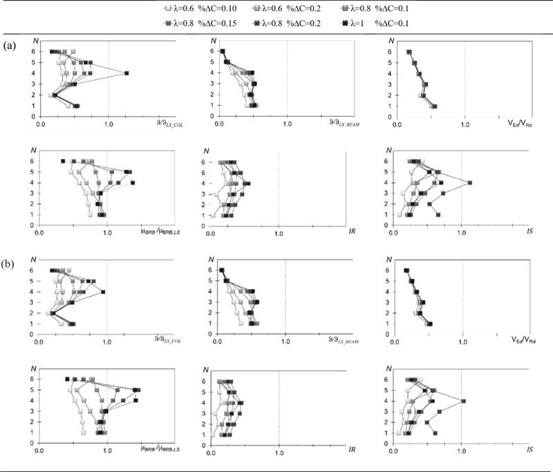
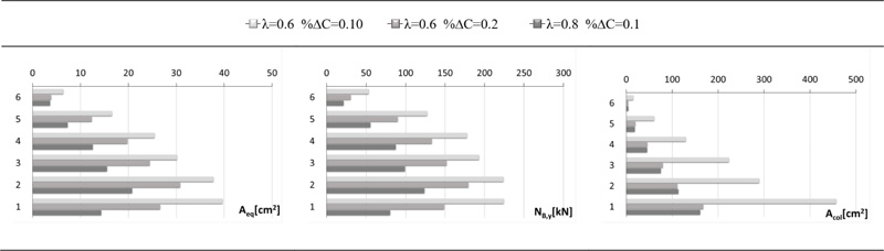
The verification of the NC performance objective shown in Fig. (8a) denotes that the chord rotation demand to capacity ratio of RC columns is much larger than that of RC beams as already observed in Section 2.2 for the bare RC frame. Indeed, the application of the exoskeleton does not alter the strength ratio between beams and columns, the flexural strength of beams remains larger than that of columns and yielding mostly occurs in columns that remain the critical members. Nevertheless, the application of the exoskeleton largely improves the response of the RC frame to the ground motions with PGA = 0.45 g and all the retrofit solutions with the exception of that obtained for λ = 1.0 lead to chord rotation demand to capacity ratio not larger than 1. The verification in terms of ductility demand of BRBs (μBRB/μB,LS) is more demanding and other two retrofit solutions exceeds the NC limit state. Hence, only three retrofit solutions meet both the conditions on chord rotation demand of RC members and ductility demand of BRBs for the NC performance objective: the two solutions designed by λ = 0.6 and the one designed by λ = 0.8 and %∆C = 0.10. The analysis of the verification of brittle mechanisms shows that they are less demanding than those of the ductile mechanisms. All the retrofit solutions satisfy the verifications for shear force of RC columns (VEd/VRd ≤ 1) and for plastic resistance of steel columns (IR ≤ 1) and none of the retrofit solutions that satisfy the verifications of ductile mechanism fails to fulfil the stability verification (IS ≤ 1). Fig. (8b) shows that the verification of the SD performance is less demanding and the three combinations of parameters that lead to satisfy the NC performance objective allow the fulfilment of all the verifications related to the SD limit state. These three retrofit solutions are compared in Fig. (9) in terms of equivalent area of the BRBs Aeq, yield strength NB,y of the BRBs and area of the columns of the exoskeleton Acol. The comparison shows that the use of λ = 0.8 greatly reduces Aeq and NB,y and therefore the size of the BRBs. The area Acol is mainly influenced by %∆C but the use of λ = 0.8 led to the minimum value of Acol. In conclusion, among the retrofit solutions that meet the NC and SD performance objectives the one associated to the set of design parameters λ = 0.8; %∆C = 0.10 is that with minimum size of the steel exoskeleton.
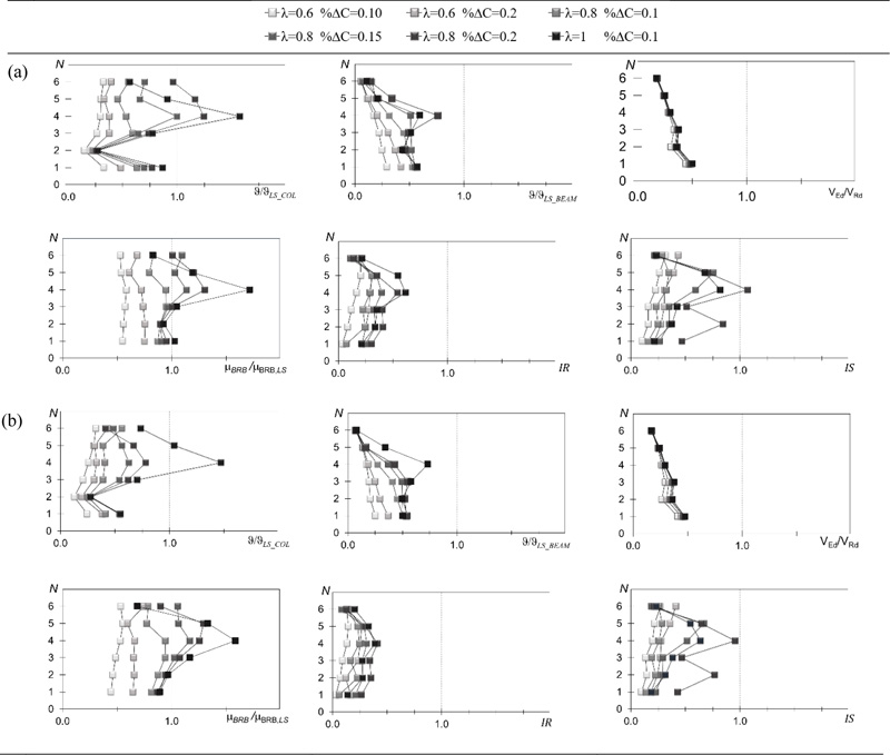
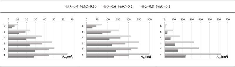
The combinations of parameters chosen for the upgrading design of the frame GL1 are used also for the frame GL2, which is made of concrete with compressive strength lower than that assumed in design and lower than that of the frame GL1. Only three combinations of parameters satisfy the requirement on the chord rotation of RC columns (Fig. 10a): the two combinations with λ = 0.6 and the one designed by λ = 0.8 and %∆C = 0.10. The verification in terms of ductility demand of BRBs, shear force of RC columns, plastic resistance and stability of steel columns lead to similar results to those of frame GL1. Hence, the two solutions designed by λ = 0.6 and the one designed by λ = 0.8 and %∆C = 0.10 satisfy all the requirements. Fig. (10b) shows that once again the verification of the SD performance objective is less demanding than that of the NC performance objective: in term of chord rotation, the combination with λ=1 is the only one that does not satisfy the ductility check of RC columns. The results of the other verifications are practically coincident with those related to the NC performance objective. Hence, also the three solutions that satisfy all the verifications related to the NC limit state lead to the fulfilment of SD limit state. Finally, these three retrofit solutions are compared in Fig. (11) in terms of equivalent area of the BRBs Aeq, yield strength NB,y of the BRBs and area of the columns of the exoskeleton Acol. The comparison shows that the use of λ = 0.8 and %∆C = 0.10 determines the smallest Aeq, NB,y and Acol, and therefore the smallest size of BRBs and steel columns.
Based on the above considerations, the recommended combination of parameters for the design of the exoskeleton equipped with BRBs is always λ=0.8; %∆C =0.10.
CONCLUSION
This paper proposes a design method for seismic upgrading of existing RC frames by a steel exoskeleton equipped with BRBs. This method allows a direct control of the story drift demand and requires the execution of an iterative process. Taking into account the characteristics of the bare RC frame, the characteristics of the BRBs to be inserted inside the exoskeleton are calculated for each floor, so that the structure does not collapse under the effect of the earthquake chosen as target. This procedure is governed by two parameters that can be tuned to optimize the design: the safety factor on drift capacity λ and the fraction %∆C. The design method was applied to upgrade two case study frame, representative of RC buildings built in the 1970s. Many projects have been carried out varying the parameters λ and %∆C, and setting the NC limit state as a target.
The design method is calibrated determining the seismic response of the upgraded frames by means of non-linear dynamic analyses. To this end, a numerical model of the RC frame and the external exoskeleton with BRBs was analysed by Opensees. The seismic performance provided by the upgraded structures is evaluated considering ground motions with probability of exceedance in 50 years of 10% and 5% associated to verifications of NC and SD limit states, respectively.
The parametric analysis allowed the identification of the combinations of the parameters that lead to the achievement of the performance objectives. Among these combinations, the one that leads to the most economically advantageous retrofit solution was chosen. In conclusion, the recommended combination of design parameters is λ = 0.8; %∆C = 0.10. Both the frames (GL1 and GL2) designed according to this combination of design parameters show suitable seismic performance for both the two considered limit states (NC and SD). Therefore, the design method is versatile because its application leads to suitable results for both buildings, even though they suffered from different levels of seismic deficiency, and it is multi-performance because it is able to satisfy the two performance objectives with a single project.
Furthermore, the possibility of using λ = 0.8 underlines the advantage of adding the steel exoskeleton. It avoids the use of λ = 0.6, recommended when the BRBs were inserted inside the RC frame. The increase of λ from 0.6 to 0.8 greatly reduces the size of the BRBs and maintains the size of the steel columns below acceptable values.
CONSENT FOR PUBLICATION
Not applicable.
AVAILABILITY OF DATA AND MATERIALS
Not applicable.
FUNDING
This study was partially supported by the program of University of Catania, Italy within the research project “SIASECA Soluzioni Innovative per l’Adeguamento Sismico di Edifici in C.A.” grant number 59722022278, “Piano di incentivi per la ricerca di Ateneo 2020/2022 (Pia.ce.ri.) Linea 2” of Department of Civil Engineering and Architecture.
CONFLICT OF INTEREST
Dr. Edwardo M. Morino is the Editorial Board Member and Dr. Melina Bosco is the Associate Editorial Board Member of The Open Construction and Building Technology Journal.
ACKNOWLEDGEMENTS
Declared none.

